Table of Contents
Advertisement
Quick Links
Advertisement
Table of Contents

Related Manuals for JCM GLOBAL DBV Series


Summary of Contents for JCM GLOBAL DBV Series
- Page 1 Website: http://www.jcmglobal.com Support: http://www.jcmglobal.com/en/contact/default.aspx Series ® Banknote Validator (DBV-400) Integration Guide Revision A, June 30, 2014 P/N 960-000175R_Rev. A {EDP #233426} © 2014, JAPAN CASH MACHINE CO., LTD. Issue #4107-IGE-01-00...
- Page 2 ® Series Banknote Validator (DBV-400) Integration Guide Issue #4107-IGE-01-00 REVISION HISTORY Rev №. Date Reason for Update Comment 6/30/14 Initial Document International Compliance • RoHS Directives • CE Mark • CB Scheme NOTE: The above listed compliance confirmations are currently being examined for approval or certification.
-
Page 3: Table Of Contents
® Series Banknote Validator (DBV-400) Table of Contents Page 1 GENERAL INFORMATION..................1 Description .......................... 1 DBV-400 Unit ........................1 Model Descriptions ......................2 Type Descriptions ....................... 2 Software Descriptions ......................2 Precautions ......................... 2 User Cautions ..........................2 Installation Cautions ........................2 Mounting, Dismounting &... - Page 4 ® Series Banknote Validator (DBV-400) Integration Guide Table of Contents Continued Page 8 TROUBLESHOOTING................... 29 Introduction ........................29 Troubleshooting Overview ....................29 Fault Table Listings ......................29 Adjustment Error ...........................30 Communication Error ........................30 LED Indication Conditions ....................31 LED Flash Error Code Conditions ....................31 LED Flash Reject Code Conditions ....................33 9 UNIT DIMENSIONS ....................
- Page 5 ® Series Banknote Validator (DBV-400) List of Figures Page Figure 1 DBV-400 Unit .....................1 Figure 2 Precautionary Symbols ................2 Figure 3 Unacceptable Banknotes ................4 Figure 4 DBV-400 Component Names ..............5 Figure 5 Thread Studs Location ................8 Figure 6 Retrieving Banknotes 1 ................16 Figure 7 Retrieving Banknotes 2 ................16 Figure 8...
- Page 6 ® Series Banknote Validator (DBV-400) Integration Guide THIS PAGE INTENTIONALLY LEFT BLANK P/N 960-000175R_Rev. A {EDP #233426} © 2014, JAPAN CASH MACHINE CO., LTD.
- Page 7 ® Series Banknote Validator (DBV-400) List of Tables Page Table 1 DBV-400 Model Number Specifications .............2 Table 2 DBV-400 Type Number Specifications ............2 Table 3 DBV-400 Software Number Specifications ..........2 Table 4 DBV-400 Technical Specifications ..............6 Table 5 DBV-400 Environmental Specifications ............6 Table 6 DBV-400 Electrical Specifications ..............7 Table 7...
- Page 8 ® Series Banknote Validator (DBV-400) Integration Guide THIS PAGE INTENTIONALLY LEFT BLANK P/N 960-000175R_Rev. A {EDP #233426} © 2014, JAPAN CASH MACHINE CO., LTD.
-
Page 9: General Information
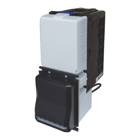
® Series Banknote Validator (DBV-400) Integration Guide R e v i s i o n A 1 GENERAL INFORMATION Description • Operational Flowchart This section provides a general overview of the • Troubleshooting Series Banknote Validator Unit (DBV-400), ® • Unit Dimensions pictured in Figure 1. -
Page 10: Model Descriptions
® Series Banknote Validator (DBV-400) Integration Guide Model Descriptions Software Descriptions Table 1 lists the product model number Table 3 lists the software number descriptions. descriptions. Table 3 DBV-400 Software Number Specifications Table 1 DBV-400 Model Number Specifications Software: DBV-400 * * * - 0 * * - V * .** Model: DBV- 4 * * - (*) * * (2)(3) (4) (5) (A) Software Model Name... -
Page 11: Mounting, Dismounting & Transportation
® Series Banknote Validator (DBV-400) Integration Guide Preventive Maintenance 4. Avoid exposing the Banknote Insertion Slot to direct Sunlight and/or Incandescent Lamp The preventive maintenance requirements are illumination having a Gradient Angle of 15 defined as follows: Degrees or more, and an illumination index of 1. -
Page 12: Banknote Fitness Requirements
® Series Banknote Validator (DBV-400) Integration Guide ANKNOTE ITNESS EQUIREMENTS The following Banknote types may not validate correctly, or worse, can cause a jam and/or damage to the unit’s Transport Path. Banknotes exhibiting the following conditions illustrated in Figure 3 should be avoided: •... -
Page 13: Component Names
® Series Banknote Validator (DBV-400) Integration Guide Component Names Figure 4 illustrates the DBV-400 component names and locations. DBV-400 Unit Inside View a) Transport Unit h) USB Connector for maintenance b) Bezel (Option) i) Interface Connector c) Banknote Insertion Slot j) USB Interface Connector d) Validation Guide k) DIP Switch 1... -
Page 14: Specifications
® Series Banknote Validator (DBV-400) Integration Guide 2 SPECIFICATIONS Technical Specifications Table 4 DBV-400 Technical Specifications 98% or greater Note: The following banknote types are excluded: • Banknotes with unclear graphics • Double (dual) Notes Acceptance Rate • Worn, dirty, wet, stained, torn or excessively wrinkled Banknotes •... -
Page 15: Electrical Specifications
® Series Banknote Validator (DBV-400) Integration Guide Hydrothermal Condition Table 40ºC/90RH% 60ºC/30RH% Allowable Operating Temperature and Humidity Range -15ºC/30RH% 10ºC/15RH% 60 70 Temperature [ºC] Electrical Specifications Table 6 DBV-400 Electrical Specifications 12V DC ±5% (Greater than 2.5A) Supply Voltage 24V DC ±5% (Greater than 1.9A) 12V DC Standby = 0.22A •... -
Page 16: Installation
® Series Banknote Validator (DBV-400) Integration Guide 3 INSTALLATION DIP Switch Configurations This section provides the denomination DIP Switch This section provides installation and operating Block 1 (DS1) and Block 2 (DS2) Settings for the instructions for the DBV-400 Banknote Validator DBV-400 Unit. -
Page 17: Connector Pin Assignments
® Series Banknote Validator (DBV-400) Integration Guide 4 CONNECTOR PIN ASSIGNMENTS Table 10 through Table 17 list the DBV-400 Unit’s pin assignments. MDB P HOTO OUPLER SOLATION ONNECTOR SSIGNMENTS Table 10 lists the DBV-400 CN1 ID-003 MDB Photo-Coupler Isolation Connector Pin Assignments. Table 10 DBV-400 CN1 ID-003 MDB Photo-Coupler Isolation Connector Pin Assignments Connector (DBV-400 Side): 74164-0118 (Molex) Housing (Cable Side):... -
Page 18: Rs232 Connector Pin Assignments
® Series Banknote Validator (DBV-400) Integration Guide RS232 C ONNECTOR SSIGNMENTS Table 11 lists the DBV-400 CN1 ID-003 RS232 Connector Pin Assignments. Table 11 DBV-400 CN1 ID-003 RS232 Connector Pin Assignments Connector (DBV-400 Side): 74164-0118 (Molex) Housing (Cable Side): 50-57-9309 SL Crimp Housing, Single Row, Version D, Back Ribs, 9 Circuits (Molex) ™... -
Page 19: Ttl Connector Pin Assignments
® Series Banknote Validator (DBV-400) Integration Guide TTL C ONNECTOR SSIGNMENTS Table 12 lists the DBV-400 CN1 ID-003 TTL Connector Pin Assignments. Table 12 DBV-400 CN1 ID-003 TTL Connector Pin Assignments Connector (DBV-400 Side): 74164-0118 (Molex) Housing (Cable Side): 50-57-9309 SL Crimp Housing, Single Row, Version D, Back Ribs, 9 Circuits (Molex) ™... -
Page 20: Id-002 Pulse Connector Pin Assignments
® Series Banknote Validator (DBV-400) Integration Guide ID-002 P ULSE ONNECTOR SSIGNMENTS Table 13 lists the DBV-400 CN1 ID-002 Pulse Connector Pin Assignments. Table 13 DBV-400 CN1 ID-002 Pulse Connector Pin Assignments Connector (DBV-400 Side): 74164-0118 (Molex) Housing (Cable Side): 50-57-9309 SL Crimp Housing, Single Row, Version D, Back Ribs, 9 Circuits (Molex) ™... -
Page 21: Id-044 Pulse Connector Pin Assignments
® Series Banknote Validator (DBV-400) Integration Guide ID-044 P ULSE ONNECTOR SSIGNMENTS Table 14 lists the DBV-400 CN1 ID-044 Pulse Connector Pin Assignments. Table 14 DBV-400 CN1 ID-044 Pulse Connector Pin Assignments Connector (DBV-400 Side): 74164-0118 (Molex) Housing (Cable Side): 50-57-9309 SL Crimp Housing, Single Row, Version D, Back Ribs, 9 Circuits (Molex) ™... -
Page 22: Id-044 Serial Connector Pin Assignments
® Series Banknote Validator (DBV-400) Integration Guide ID-044 S ERIAL ONNECTOR SSIGNMENTS Table 15 lists the DBV-400 CN1 ID-044 Serial Connector Pin Assignments. Table 15 DBV-400 CN1 ID-044 Serial Connector Pin Assignments Connector (DBV-400 Side): 74164-0118 (Molex) Housing (Cable Side): 50-57-9309 SL Crimp Housing, Single Row, Version D, Back Ribs, 9 Circuits (Molex) ™... -
Page 23: Usb Connector Pin Assignments
® Series Banknote Validator (DBV-400) Integration Guide USB C ONNECTOR SSIGNMENTS Table 16 lists the DBV-400 CN2 USB Interface Connector Pin Assignments. Table 16 DBV-400 CN2 USB Interface Connector Pin Assignments Connector (DBV-400 Side):S4B-XH-A (JST) Housing (Cable Side): XHP-4B (JST) Contact (Cable Side): SXH-001T-PO.6 (JST) Pin No. -
Page 24: Preventive Maintenance
® Series Banknote Validator (DBV-400) Integration Guide 5 PREVENTIVE MAINTENANCE Retrieving Banknotes To retrieve Cash Box deposited Banknotes, perform the following steps: 1. Press the Cash Box Release Button (See Figure 6 a) and slightly pull upward and then out in the direction indicated by the red arrow. -
Page 25: Cleaning Procedure
® Series Banknote Validator (DBV-400) Integration Guide Cleaning Procedure To clean the DBV-400 Validation Section, gently rub the Sensors and Rollers clean using a dry, soft, lint-free, Micro-fiber Cloth ONLY. Do not use any Alcohol, solvents, Citrus based products, surface acting agents or scouring agents that may cause damage to the Validation Section Sensors and/or Rollers. -
Page 26: Sensor And Roller Locations
® Series Banknote Validator (DBV-400) Integration Guide ENSOR AND OLLER OCATIONS Figure 12 illustrates the various DBV-400 Unit’s sensor and roller cleaning locations. Table 18 lists the DBV-400 sensor type cleaning methods. NOTE: Clean Rollers using a lint-free slightly damp with water Micro-fiber Cloth first, and then wipe off using a dry, lint-free, Micro-fiber Cloth to absorb liquids. -
Page 35: Operational Flowchart
® Series Banknote Validator (DBV-400) Integration Guide 7 OPERATIONAL FLOWCHART Figure 20 depicts Part One of a typical DBV-400 Initialization Banknote acceptance flow process. a) Apply Power to the Unit. b) Initializing C) Return from “Stacking” Flow (See Figure 22) c) Stand-by d) Enable Acceptance? e) External LED Display shows No Accept... -
Page 36: Operational Flowchart (Continued 1)
® Series Banknote Validator (DBV-400) Integration Guide Operational Flowchart (Continued 1) Figure 21 depicts Part Two of a typical DBV-400 Validation Banknote acceptance flow process. A) From “Initialize” Flow (See Figure 20) a) Is the Banknote Authentic? b) Is the Banknote acceptable? c) Denomination Signal Output d) Has STACK Command been received? D) To “f”... -
Page 37: Troubleshooting
® Series Banknote Validator (DBV-400) Integration Guide 8 TROUBLESHOOTING This section provides troubleshooting instructions in locating any causes of failure and the possible for the DBV-400 Banknote Validator Units, includ- fault location. ing the following information: Perform all repairs by referring to Calibration and •... -
Page 38: Adjustment Error
® Series Banknote Validator (DBV-400) Integration Guide Table 19 General Fault Conditions (Continued) Symptoms/Error Possible Fault Causes Corrective Action Required Messages Incorrect software Download the correct Software for Currency being accepted. (different Currency type). Banknotes are not being Make sure the Banknote values required are included in the Software accepted by the Software. -
Page 39: Led Indication Conditions
® Series Banknote Validator (DBV-400) Integration Guide LED Indication Conditions The External LED Display indicates various com- NOTE: Error Codes and Reject Codes flash binations of solid or alternating Color light flashing different patterns when in the normal operation conditions when any of the Standard Error and mode (communicating with the Host Machine) or Reject Codes listed in Table 22 and Table 23 occur. - Page 40 ® Series Banknote Validator (DBV-400) Integration Guide Table 22 LED Flash Error Codes (Continued) Normal Performance Operation Test Error Causes and Solutions Sequence Sequence While operating the Stacker Motor, no pulse inputs occurred greater than the specified value. Stacker Motor [Solution] Check that the following parts are properly assembled and/or Lock-UP Harness connected.
-
Page 41: Led Flash Reject Code Conditions
® Series Banknote Validator (DBV-400) Integration Guide LED F LASH EJECT ONDITIONS Table 23 lists the various LED Flash Reject Code causes & solutions for Banknotes Table 23 LED Flash Reject Codes Normal Performance Operation Test Error Causes and Solutions Sequence Sequence When adjusting Banknote data, Sensors detected an abnormal Banknote... - Page 42 ® Series Banknote Validator (DBV-400) Integration Guide Table 23 LED Flash Reject Codes (Continued) Normal Performance Operation Test Error Causes and Solutions Sequence Sequence Sensors detected an incorrect set specification value. Yellow Green Fraud Detection [Solution] Check the DBV-400 Unit’s conditions. Check that the Banknote is not damaged nor exhibiting unfit conditions.
-
Page 43: Unit Dimensions
® Series Banknote Validator (DBV-400) Integration Guide 9 UNIT DIMENSIONS Entire Unit Outside Dimensions Figure 23 illustrates the DBV-400 Unit with JCM Standard Bezel outside dimensions. 61.7 2x5.4 74.7 50.8 24.9 31.4 153.3 98.2 34.9 NOTE: All dimensions in millimeters Figure 23 DBV-400 Unit With JCM Standard Bezel Outside Dimensions Figure 24 illustrates the DBV-400 Unit with Snack Mask Bezel outside dimensions. -
Page 44: Entire Unit Outside Dimensions (Continued)
® Series Banknote Validator (DBV-400) Integration Guide Entire Unit Outside Dimensions (Continued) Figure 25 illustrates the DBV-400 Unit with TOB Type Bezel outside dimensions. 2-5.3 77.7 50.8 12.5 156.3 81.2 30.5 104.2 NOTE: All dimensions in millimeters Figure 25 DBV-400 Unit With TOB Type Bezel Outside Dimensions P/N 960-000175R_Rev. -
Page 45: 10 Technical Contact Information
® Series Banknote Validator (DBV-400) Integration Guide 10 TECHNICAL CONTACT INFORMATION To obtain further technical information regarding the DBV-400 device, please contact the nearest location listed below: SIA AND CEANIA MERICAS JCM Gold (HK) Ltd. JCM American Phone: +852-2429-7187 Phone: +1-702-651-0000 Fax: +852-2929-7003 Fax: +1-702-644-5512 Unit 1-7, 3/F., Favor Industrial Centre... - Page 46 ® Series Banknote Validator (DBV-400) Integration Guide THIS PAGE INTENTIONALLY LEFT BLANK P/N 960-000175R_Rev. A {EDP #233426} © 2014, JAPAN CASH MACHINE CO., LTD.
-
Page 47: Index
® Series Banknote Validator (DBV-400) Index 11 INDEX Banknote Jam Pin Assignments clearing a... 16 Table Listing of... 9 Banknote Validator Precautionary Symbols general information describing a... 1 types of... 2 Primary Features DBV-400 ... 4 DBV Product Series of Cleaning methods of, and equipment required for... - Page 48 ® Series Banknote Validator (DBV-400) Integration Guide THIS PAGE INTENTIONALLY LEFT BLANK P/N 960-000175R_Rev. A {EDP #233426} © 2014, JAPAN CASH MACHINE CO., LTD.
- Page 49 ® Series Banknote Validator (DBV-400) Integration Guide P/N 960-000175R_Rev. A {EDP #233426} © 2014, JAPAN CASH MACHINE CO., LTD.
- Page 50 ® Series Banknote Validator (DBV-400) Integration Guide Issue #4107-IGE-01-00 P/N 960-000175R_Rev. A {EDP #233426} © 2014, JAPAN CASH MACHINE CO., LTD.
Need help?
Do you have a question about the DBV Series and is the answer not in the manual?
Questions and answers