Table of Contents
Advertisement
Advertisement
Table of Contents

Related Manuals for JCM GLOBAL TBV Series


Summary of Contents for JCM GLOBAL TBV Series
- Page 1 Support: http://www.jcmglobal.com/en/contact/default.aspx Web-Site: http://www.jcmglobal.com Series ™ Transaction Based Validator Integration Guide Revision A, August 6, 2010 P/N 960-100925R_Rev. A {EDP #186705} Issue #4060-IGE-01-00 © 2010, Japan CashMachine Co, Limited...
- Page 2 TBV™ Series Transaction Based Validator Integration Guide Issue #4060-IGE-01-00 REVISION HISTORY Rev №. Date Reason for Update Comment 8-06-10 Initial Document International Compliance • RoHS Directives • UL/c-UL Mark • CE Mark • CB Scheme JPULA-03013 • FCC Directives FCC WARNING Changes or modifications not expressly approved by the party responsible for compliance could void the user’s authority to operate the equipment.
-
Page 3: Table Of Contents
TBV™ Series Integration Guide Table of Contents Page 1 GENERAL INFORMATION..................1 Description .......................... 1 TBV Unit..........................1 Component Names ......................2 Primary Features ........................ 3 Model Descriptions ......................3 Type Descriptions ....................... 3 Software Descriptions ......................3 Precautions ......................... 3 User Cautions .......................... - Page 4 Table of Contents Page 11 INTERNATIONAL COMPLIANCE................. 29 12 TECHNICAL CONTACT INFORMATION ............. 30 Americas & Oceania........................30 JCM Global ..........................30 Europe, Africa, Russia & Middle East ...................30 JCM Europe GmbH ........................30 UK & Ireland ..........................30 JCM Europe (UK Office)......................30 Asia ...............................30 JCM Gold (HK) Ltd.
- Page 5 TBV™ Series Integration Guide List of Figures Page Figure 1 Transaction Based Validator Unit (TBV) ............1 Figure 2 TBV Individual Major Component Names.............2 Figure 3 Precautionary Symbols .................3 Figure 4 Unacceptable Banknotes ................4 Figure 5 Fan-Flipping Banknotes ................4 Figure 6 Aligning Banknotes Edges ................4 Figure 7 M4 Screw Locations (Right &...
- Page 6 TBV™ Series Integration Guide List of Figures THIS PAGE INTENTIONALLY LEFT BLANK P/N 960-100925R_Rev. A {EDP #186705} © 2010, Japan CashMachine Co, Limited...
- Page 7 TBV™ Series Integration Guide List of Tables Page Table 1 TBV Software Number Specifications ............3 Table 2 TBV Type Specifications ................3 Table 3 TBV Software Number Specifications ............3 Table 4 TBV Technical Specification................5 Table 5 TBV Environmental Specification ..............6 Table 6 TBV Electrical Specification ................6 Table 7 TBV Structural Specification................6...
- Page 8 TBV™ Series Integration Guide List of Tables THIS PAGE INTENTIONALLY LEFT BLANK P/N 960-100925R_Rev. A {EDP #186705} © 2010, Japan CashMachine Co, Limited...
-
Page 9: Tbv™ Series
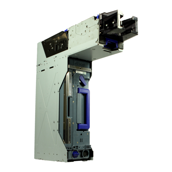
TBV™ Series Transaction Based Validator Integration Guide R e v i s i o n A 1 GENERAL INFORMATION Description • LED Diagnostics • Unit Dimensions This section provides a general overview of the • International Compliance Transaction Based Validator Unit (TBV) pictured •... -
Page 10: Component Names
Transaction Based Validator Integration Guide Component Names Figure 2 illustrates the TBV Component Names and Locations. Frame Section Transport Section Section Cash Box BNF Unit TBV Frame Unit (Base Side View) (Front End View - No Bezel) a) Return Path Open/Close Cover o) Cash Box Lock Lever (Back Side) b) BNF Guide Latch p) Cash Box Release Lever... -
Page 11: Primary Features
Transaction Based Validator Integration Guide Primary Features Software Descriptions The TBV Series of Banknote Validator contains the Table 3 lists the various Software Number following primary features: Descriptions. • Ability to accept 50 Banknotes at a time. Table 3 TBV Software Number Specifications •... -
Page 12: Mounting, Dismounting & Transportation
Transaction Based Validator Integration Guide 6. When installing the equipment, connect the Banknotes exhibiting the conditions listed below Frame Unit to the Frame Ground of the Host and illustrated in Figure 4 should be avoided: Machine. • Having perforated or torn areas 7. -
Page 13: Specifications
Transaction Based Validator Integration Guide 2 SPECIFICATIONS Technical Specifications Table 4 TBV Technical Specification 98% or greater Note: The following banknote types are excluded: a) Worn, dirty wet, stained, torn or excessively wrinkled Banknotes b) Double (dual) Banknotes c) Banknotes adhering Oil or Iron powder Acceptance Rate: d) Banknotes having folded corners or edges e) Banknotes with excessive or inadequate magnetism or unclear graphics... -
Page 14: Environmental Specifications
Transaction Based Validator Integration Guide Environmental Specifications Table 5 TBV Environmental Specification Operating Temperature: +5ºC to +50ºC (41ºF to 122ºF) Storage Temperature: -20ºC to +60ºC (-4ºF to 140ºF) Relative Operating Humidity: 30% to 80% RH (non-condensed) Relative Storage Humidity: 30% to 80% RH (non-condensed) Avoid contact with direct sunlight (Interior lighting must be incandescent with a ... -
Page 15: Installation
Transaction Based Validator Integration Guide 3 INSTALLATION 4. Connect the TBV Unit to the Host Machine using a packaged Harness, and then supply the power. Installation Process NOTE: To install the TBV Unit into a Host Perform the following steps to install the TBV Machine, affix at least two of the four side Unit: dimension in place. -
Page 16: Primary Led Indications
Transaction Based Validator Integration Guide Table 11 TBV Centering Mechanism & Select Comm Interface Switches DS4 Set Identical Switch No. Switch ON Switch OFF Fixed Model Centering Model Barcode Coupon Barcode Coupon Single Read Double Read I/F Selection Switch #3 Switch #4 †... -
Page 17: Connector Pin Assignments
Transaction Based Validator Integration Guide 4 CONNECTOR PIN ASSIGNMENTS Table 15 through Table 18 list the TBV Pin Assignments respectively. Table 15 lists the TBV USB Interface Pin Assignments. Table 15 TBV USB Interface Pin Assignments Back Side View Frame Ground Socket (Transport Unit Side): DR1P026SA1 (JCM) Socket (Frame Unit Side): DR1R026PA1 (JCM) Contact (Frame Unit Side): D02-22-22P-10000 (JAE) (Pole# 1,9,18 &... -
Page 18: Table 16 Tbv Photo-Coupler Interface Pin Assignments
Transaction Based Validator Integration Guide Table 16 lists the TBV Photo-Coupler Interface Pin Assignments Table 16 TBV Photo-Coupler Interface Pin Assignments Back Side View Frame Ground Socket (Transport Unit Side): DR1P026SA1 (JCM) Socket (Frame Unit Side): DR1R026PA1 (JCM) Contact (Frame Unit Side): D02-22-22P-10000 (JAE) (Pole# 1,9,18 & 26) UL3443 AWG#24 Ø1.3mm or less D02-22-26P-10000 (JAE) (Poles except 1,9,18 &... -
Page 19: Table 17 Tbv Rs232 Interface Pin Assignments
Transaction Based Validator Integration Guide Table 17 lists the TBV RS232 Interface Pin Assignments Table 17 TBV RS232 Interface Pin Assignments Back Side View Frame Ground Frame Ground Socket (Transport Unit Side): DR1P026SA1 (JCM) Socket (Frame Unit Side): DR1R026PA1 (JCM) Contact (Frame Unit Side): D02-22-22P-10000 (JAE) (Pole# 1,9,18 &... -
Page 20: Table 18 Tbv Cctalk Interface Pin Assignments
Transaction Based Validator Integration Guide Table 18 lists the TBV ccTalk Interface Pin Assignments. Table 18 TBV ccTalk Interface Pin Assignments Back Side View Frame Ground Socket (Transport Unit Side): DR1P026SA1 (JCM) Socket (Frame Unit Side): DR1R026PA1 (JCM) Contact (Frame Unit Side): D02-22-22P-10000 (JAE) (Pole# 1,9,18 & 26) UL3443 AWG#24 Ø1.3mm or less D02-22-26P-10000 (JAE) (Poles except 1,9,18 &... -
Page 21: Preventive Maintenance
Transaction Based Validator Integration Guide 5 PREVENTIVE MAINTENANCE 1. Open the Return Path Open/Close Cover, and remove the jammed Banknote (See Figure 11 a). Retrieving Banknotes 2. If the Banknote jam location is not evident, open the BNF Section’s Upper Guide by simultan- To retrieve TBV Cash Box deposited Banknotes, eously pressing in on the BNF Guide Latches perform the following steps:... -
Page 22: Cleaning Procedure
Transaction Based Validator Integration Guide 8. If necessary, remove the Cash Box (See Figure 13 a) from the Frame, and remove the jammed Bank- note as shown in Figure 13b (Review Figure 9 “Removing the Cash Box” on page 13 of this Guide if necessary to properly remove the Cash Box). -
Page 23: Tbv Sensor And Roller Locations
Transaction Based Validator Integration Guide 6 TBV SENSOR AND ROLLER LOCATIONS Figure 14 illustrated the various TBV Sensor and Roller cleaning locations, and Table 19 lists the TBV Sensor and Roller Type Cleaning Methods respectively. Transport Section (Upper Door Open) BNF Section (Upper Portion Open) Transport Section... -
Page 24: Operational Flowchart
Transaction Based Validator Integration Guide 7 OPERATIONAL FLOWCHART Figure 15 depicts a typical TBV Banknote acceptance flow process. Power applied to the Unit. B) Return from “t” or “u” Functions below a) Initializing A) Return from “p” or “r” Functions below b) Has ENABLE Command been ... -
Page 25: Standard Interface Circuit Schematics
Transaction Based Validator Integration Guide 8 STANDARD INTERFACE CIRCUIT SCHEMATICS Figure 16 illustrates the TBV USB Interface Schematic Diagram CONTROLLER SIDE EXAMPLE TBV SIDE INTERFACE CONNECTOR To CPU Reset (Direct Connection) USB Specification Rev 2.0 Maximum Speed = 12Mbps * Connect FG to a Chassis Frame Ground Figure 16 TBV USB Interface Schematic Diagram P/N 960-100925R_Rev. -
Page 26: Standard Interface Circuit Schematics (Continued 1)
Transaction Based Validator Integration Guide TANDARD NTERFACE IRCUIT CHEMATICS ONTINUED Figure 17 illustrates the TBV Photo-Coupler Interface Schematic Diagram CONTROLLER SIDE EXAMPLE TBV SIDE INTERFACE CONNECTOR DIP-SW #5 (Shown ON) OFF: RS232 (Default) ON: Photo-Coupler To CPU Reset (Direct Connection) * Connect FG to a Chassis Frame Ground Figure 17 TBV Photo-Coupler Interface Schematic Diagram... -
Page 27: Standard Interface Circuit Schematics (Continued 2)
Transaction Based Validator Integration Guide TANDARD NTERFACE IRCUIT CHEMATICS ONTINUED Figure 18 illustrates the TBV RS232 Interface Schematic Diagram CONTROLLER SIDE EXAMPLE TBV SIDE INTERFACE CONNECTOR DIP-SW #5 (Shown OFF) OFF: RS232 (Default) ON: Photo-Coupler To CPU Reset (Direct Connection) * Connect FG to a Chassis Frame Ground Figure 18 TBV RS232 Interface Schematic Diagram... -
Page 28: Standard Interface Circuit Schematics (Continued 3)
Transaction Based Validator Integration Guide TANDARD NTERFACE IRCUIT CHEMATICS ONTINUED Figure 19 illustrates the TBV ccTalk Interface Schematic Diagram. CONTROLLER SIDE EXAMPLE TBV SIDE INTERFACE CONNECTOR To CPU Reset (Direct Connection) * Connect FG to a Chassis Frame Ground Figure 19 TBV ccTalk Interface Schematic Diagram P/N 960-100925R_Rev. -
Page 29: Led Diagnostic Codes
Transaction Based Validator Integration Guide 9 LED DIAGNOSTIC CODES Malfunction LED Error Codes The TBV Bezel LEDs light a solid Color, or flash a combination of three (3) different Colors when errors, Banknote jams or a Note Reject Error occurs. The TBV Status, Error Codes, Banknote Jam Code or Bank-note Reject Codes are indicated by the number and/or Color of the Status LED’s solid or flashing light condition. -
Page 30: Standard Error And Reject Codes
Transaction Based Validator Integration Guide Standard Error and Reject Codes The Bezel LED indicates various solid/flashing Color lighting conditions when any of the Standard Errors listed in Table 21 occur. Identify the cause and solutions for these indications from each Table listing and ensure that the relative assembles are properly connected and/or harnessed, and that all of the Unit’s ... - Page 31 Transaction Based Validator Integration Guide Table 21 Standard LED Error Codes (Continued) On-line Off-line LED Color LED Color Error Causes and Solutions (Flash (Flash Sequence) Sequence) While operating the Stack Motor, no pulse inputs exist greater than the rated value. [Solution] Check that the following parts are properly assembled and/or Harness Stack Motor connected.
- Page 32 Transaction Based Validator Integration Guide Table 21 Standard LED Error Codes (Continued) On-line Off-line LED Color LED Color Error Causes and Solutions (Flash (Flash Sequence) Sequence) Input Voltage is too low. [Solution] Check that the following parts are properly assembled and/or Harness Voltage Problem connected.
-
Page 33: Reject Error Codes
Transaction Based Validator Integration Guide Reject Error Codes Table 22 lists the various LED Flash Reject Code causes & solutions. Table 22 LED Flash Reject Error Codes On-line Off-line LED Color Error Causes and Solutions LED Color (Flash (Lit) Sequence) The Banknote has been inserted in an incorrect direction. - Page 34 Transaction Based Validator Integration Guide Table 22 LED Flash Reject Error Codes (Continued) On-line Off-line LED Color Error Causes and Solutions LED Color (Flash (Lit) Sequence) The Line Sensors calculated a Banknote length longer or shorter than the rated value. Green Banknote Length [Solution] Check that the following parts are properly assembled and/or Harness...
-
Page 35: Unit Dimensions
Transaction Based Validator Integration Guide 10 UNIT DIMENSIONS TBV Entire Unit Outside Dimensions Figure 20 illustrates the TBV Unit’s entire outside dimensions. NOTE: All Dimension are in Millimeters Figure 20 TBV Banknote Acceptor’s Outside Dimensions P/N 960-100925R_Rev. A {EDP #186705} ©... -
Page 36: Tbv Unit Clearance Dimensions
Transaction Based Validator Integration Guide TBV U LEARANCE IMENSIONS Figure 21 illustrates the TBV Unit clearance dimensions. NOTE: All Dimension are in Millimeters Figure 21 TBV Banknote Acceptor’s Clearance Dimensions TBV Cash Box Outside Dimensions Figure 22 illustrates the TBV entire Unit outside dimensions. Gasket Seal Clearance NOTE: All Dimension are in Millimeters Figure 22 TBV Banknote Acceptor Cash Box Outside Dimensions... - Page 37 Transaction Based Validator Integration Guide 11 INTERNATIONAL COMPLIANCE • RoHS Directives • UL/c-UL Mark • CE Mark • CB Scheme JPULA-03013 • FCC Directives FCC WARNING Changes or modifications not expressly approved by the party responsible for compliance could void the user’s authority to operate the equipment.
- Page 38 Transaction Based Validator Integration Guide 12 TECHNICAL CONTACT INFORMATION & O MERICAS CEANIA JCM Gold (HK) Ltd. JCM Global Phone: +852-2429-7187 Phone: +1-702-651-0000 Fax: +852-2929-7003 Fax: +1-702-644-5512 Unit 1-7, 3/F., Favor Industrial Centre 925 Pilot Road, Las Vegas, NV 89119 2-6 Kin Hong Street, Kwai Chung, E-mail: customerservice@jcmglobal.com...
- Page 39 TBV™ Series Integration Guide Index 13 INDEX Banknote Jam Safety clearing a pictographs indicating … … procedures for 1 to 3 Safety Symbols inside boxed area Special Notes italic text highlights … Cleaning Finger Symbol pointing to … methods of, and equipment required for Steps …...
- Page 40 TBV™ Series Integration Guide Index THIS PAGE INTENTIONALLY LEFT BLANK P/N 960-100925R_Rev. A {EDP #186705} © 2010, Japan CashMachine Co, Limited...
- Page 41 TBV™ Series Integration Guide Index P/N 960-100925R_Rev. A {EDP #186705} © 2010, Japan CashMachine Co, Limited...
- Page 42 TBV™ Series Integration Guide Issue #4060-IGE-01-00 P/N 960-100925R_Rev. A {EDP #186705} © 2010, Japan CashMachine Co, Limited...
Need help?
Do you have a question about the TBV Series and is the answer not in the manual?
Questions and answers