Sign In
Upload
Download
Table of Contents
Contents
Add to my manuals
Delete from my manuals
Share
URL of this page:
HTML Link:
Bookmark this page
Add
Manual will be automatically added to "My Manuals"
Print this page
×
Bookmark added
×
Added to my manuals
Manuals
Brands
Festo Manuals
Control Unit
CPV-D102
Elektronics manual
Festo CPV-D102 Elektronics Manual
With field bus direct connection
Hide thumbs
1
2
3
4
5
6
7
8
9
10
11
12
13
14
15
16
17
18
19
20
21
22
23
24
25
26
27
28
29
30
31
32
33
34
35
36
37
38
39
40
41
42
43
44
45
46
47
48
49
50
51
52
53
54
55
56
57
58
59
60
61
62
63
64
65
66
67
68
69
70
71
72
73
74
75
76
77
78
79
80
81
82
83
84
85
86
87
88
89
90
91
92
93
94
95
96
97
98
99
100
101
102
103
104
105
106
107
108
109
110
111
112
113
114
115
116
117
118
119
120
121
122
123
124
125
126
127
128
129
130
131
132
133
134
135
136
137
138
139
140
141
142
143
144
145
146
147
148
149
150
151
152
153
154
page
of
154
Go
/
154
Contents
Table of Contents
Bookmarks
Table of Contents
Table of Contents
Intended Use
Target Group
Service
Notes on the Use of this Manual
Important User Instructions
Installation CPV−DI02 and CPV−CS02
Installation Cpv−Di02 and Cpv−Cs02
General Instructions on Installation
Electrical Connecting and Display Elements
Overview for Setting the CPV Direct
Setting the Station Number
Setting the Diagnostic Mode (CPV−DI02) or the Load Voltag Monitoring (CPV−CS02)
Recognizing the CPI Extension with the SAVE Button
Help Table for Setting the Station Number
Connecting the Field Bus
Field Bus Cable
Field Bus Baud Rate and Field Bus Length for PROFIBUS−DP (CPV−DI02)
Field Bus Interface
Connection Possibilities
Bus Termination with Termination Resistors (CPV−DI02)
Installation CPV−DI02 and CPV−CS02
Connecting the Power Supply
Cable for Power Supply
Selecting the Power Unit
Connecting the Power Supply
Extending the CPV Direct
Rules for Extending the CPI System
Preparing the CPI System for Commissioning
Checking the CP Strings
Saving the String Assignment
Switching−On Reaction of the CPI System
Reaction of the CPI System to Faults in Operation
Eliminating Assignment Faults
Replacing CPI/CP Modules
Commissioning Cpv−Di02 (Profibus−Dp)
Commissioning CPV−DI02 (PROFIBUD−DP)
Preparing the CPV Direct for Commissioning
Switching on the Power Supply
Address Assignment of the CPV Direct
Address Assignment of CPI/CP Modules
Information on Commissioning
Device Master File (GSD) and Icon Files
Configuration with a Siemens Master
STEP 7 HW Config (up to V 5.2) Preparations
Station Selection with STEP
Configuration with STEP
Tool Change Configuration
Examples of Configuration
Tool Change Configuration
Diagnosis CPV−DI02 (PROFIBUS−DP)
Diagnosis Cpv−Di02 (Profibus−Dp)
Diagnosis CPV−DI02 (PROFIBUS−DP)
Diagnosis Via Leds
Normal Operating Status
Fault Diagnosis with the Leds
Leds for Status Display of the Valve Solenoid Coils
Diagnosis Via PROFIBUS−DP
Diagnostic Words
Diagnosis Steps
Overview of the Diagnostic Bytes
Details for Standard Diagnostic Information
Diagnosis with Tool Change Configuration
Fault Treatment
Siemens SIMATIC S7
Online Diagnosis with STEP 7
Read out Diagnostic Buffer with STEP 7 (up to V 5.2)
Device−Related Diagnosis with STEP 7 (up to V 5.2)
Short Circuit/Overload
Output Module
Sensor Supply on One Input Module
Commissioning CPV−CS02 (ABB CS31)
Commissioning Cpv−Cs02 (Abb Cs31)
Preparing the CPV Direct for Commissioning
Switching on the Operating Voltages
Address Assignment of the CPV Direct
General Data
Configuration
CS31 CPU as Bus Master
Diagnosis CPV−CS02 (ABB CS31)
Diagnosis Cpv−Cs02 (Abb Cs31)
Diagnosis Via Leds
Normal Operating Status
Fault Diagnosis with the Leds
Leds for Status Display of the Valve Solenoid Coils
Diagnosis Via the Field Bus
Setting the Diagnostic Mode
Fault Treatment
Reaction of the CPV Direct to Faults
Short Circuit/Overload at an Output Module
Short Circuit in the Sensor Supply at an Input Module
Technical Appendix
Technical Appendix
Technical Specifications
Common Technical Specifications of CPV−DI02 and CPV−CS02
Technical Specifications for the CPV−DI02
Technical Specifications for the CPV−CS02
PROFIBUS−DP: Commissioning with the General DP Master
Bus Start
Send Parametriziung Data
Check the Configuration Data
Transferring Input and Output Data
Read Diagnostic Information
Implemented Functions and Service Access Points (SAP
Bus Parameters/Reaction Times
Transmission Times on the PROFIBUS−DP
Accessories
Power Supply
Index
Advertisement
Quick Links
1
Setting the Station Number
2
Commissioning Cpv−Di02 (Profibus−Dp)
Download this manual
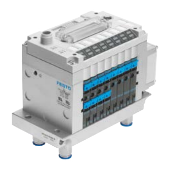
Compact performance
Elektronics manual
CPV valve terminal
with field bus direct
connection
Types:
CPV...−DI02
PROFIBUS−DP
CPV...−CS02
ABB CS31
Manual
548 732
en 0704NH
[706 006]
Table of
Contents
Previous
Page
Next
Page
1
2
3
4
5
Advertisement
Chapters
Table of Contents
5
Installation Cpv−Di02 and Cpv−Cs02
16
Commissioning Cpv−Di02 (Profibus−Dp)
60
Diagnosis Cpv−Di02 (Profibus−Dp)
80
Commissioning Cpv−Cs02 (Abb Cs31)
108
Diagnosis Cpv−Cs02 (Abb Cs31)
118
Technical Appendix
132
Table of Contents
Need help?
Do you have a question about the CPV-D102 and is the answer not in the manual?
Ask a question
Questions and answers
Related Manuals for Festo CPV-D102
Control Unit Festo CPV DI02 Series Brief Description
Cpv valve terminal with direct connection, profibus-dp (62 pages)
Control Unit Festo CPV-DI01 Manual
(200 pages)
Control Unit Festo Smart cubic CPV-SC Series Manual
Valve terminal (80 pages)
Control Unit Festo CPVSC1-VI Manual
Cpv-sc valve terminal (92 pages)
Control Unit Festo Compact Performance Series Programming And Diagnosis
Valve terminal with direct link (77 pages)
Control Unit Festo CPV-DI02 Elektronics Manual
With field bus direct connection (154 pages)
Control Unit Festo CPVSC1-M1H-D-H-M5C Assembly Instructions
Solenoid valve (2 pages)
Control Unit Festo CPX-CM-HPP Description
Control block, terminal cpx, fhpp interface (104 pages)
Control Unit Festo CPX-FB14 Brief Description
Cpx-terminal field bus node (74 pages)
Control Unit Festo CPX-E-EP Manual
System cpx-e, bus module, protocol, ethernet/ip, modbus tcp, industrial ethernet 2-port (52 pages)
Control Unit FESTO CPX Series Brief Description
Pressure sensor module (38 pages)
Control Unit Festo CPX Series Manual
Cpx terminal output module (150 pages)
Control Unit Festo CPX-CMAX-C1-1 Brief Description
Positioning module (38 pages)
Control Unit Festo CP-E16 Series Manual
Compact performance cp modules (67 pages)
Control Unit Festo CPX-AP-I-8DI-M12-5P Instructions & Operating
Digital input module (18 pages)
Control Unit Festo CPX-AP-A-8DO-M12-5P Operating Instructions Manual
Digital output module (16 pages)
This manual is also suitable for:
Cpv-di02
Profibud-dp
Cpv-cs02
Abb cs31
Profibus-dp
Cpv-di02 profibus-dp series
...
Show all
Cpv-cs02 abb cs31 series
Table of Contents
Print
Rename the bookmark
Delete bookmark?
Delete from my manuals?
Login
Sign In
OR
Sign in with Facebook
Sign in with Google
Upload manual
Upload from disk
Upload from URL


Need help?
Do you have a question about the CPV-D102 and is the answer not in the manual?
Questions and answers