Festo CPX-E-EP Manual
System cpx-e, bus module, protocol, ethernet/ip, modbus tcp, industrial ethernet 2-port
Hide thumbs
Also See for CPX-E-EP:
- Instructions for use (3 pages) ,
- Instructions & operating (4 pages) ,
- Translation of the original instructions (64 pages)

Related Manuals for Festo CPX-E-EP


Summary of Contents for Festo CPX-E-EP
- Page 1 System CPX-E Bus module CPX-E-EP Description Protocol EtherNet/IP Modbus TCP Industrial Ethernet 2-Port Function Parameterisation 8071171 2017-07 [8071173]...
- Page 2 ® EtherNet/IP , IO-Link , Modbus and RSLogix are registered trademarks of the respective trademark owners in certain countries. Symbols used: Note Material damage or loss of function Recommendations, tips, references to other documentation Festo – CPX-E-EP-EN – 2017-07 –...
-
Page 3: Table Of Contents
............Festo – CPX-E-EP-EN – 2017-07 – English... - Page 4 ..................Festo – CPX-E-EP-EN – 2017-07 – English...
-
Page 5: About This Document
Bus module CPX-E-EP, revision 1 onward Tab. 1.2 The product version can be identified from the product label or with the help of appropriate software from Festo. Appropriate software for identifying the product version can be found in the Festo Support Portal è... -
Page 6: Product Labelling
The product label is located on the left-hand side of the module. Scanning the printed Data Matrix Code with an appropriate device opens the Festo Support Portal with the relevant documents for the product. Alternatively, the Product Key (11-character alphanumeric code on the product label) can be entered in the Support Portal search box. -
Page 7: Function
The bus module is configured in the control software for the higher-order controller using a device description file (EDS file). This contains all the information required to parameterise the system CPX-E via control software (e.g. RSLogix 5000). The device description file is available on the Festo Support Portal (è www.festo.com/sp). 2.1.3 Crossover detection (auto MDI/MDI-X) The product supports crossover detection (auto MDI/MDI-X), so both patch cables and crossover cables can optionally be used. -
Page 8: Product Design
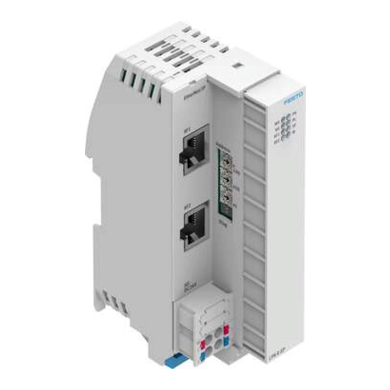
Connection/data traffic [XF1]/[XF2] (green) 2 System-specific LED indicators: – Power supply U [PS] (green) EL/SEN – Load power supply U [PL] (green) – System fault [SF] (red) – Force mode [M] (yellow) Fig. 2.2 Festo – CPX-E-EP-EN – 2017-07 – English... -
Page 9: Control Components
I/O diagnostic interface activated DIL 2: OFF DIL 1: ON Reserved DIL 2: ON 1) Factory setting Tab. 2.2 Changes to the rotary and DIL switches only take effect following a restart of the bus module. Festo – CPX-E-EP-EN – 2017-07 – English... -
Page 10: Connecting Components
64 bytes for inputs and 64 bytes for outputs. – Activated diagnostic functions as well as status bits or the I/O diagnostic interface reduce the size of the available address space. Festo – CPX-E-EP-EN – 2017-07 – English... -
Page 11: Addressing
1. Bus module with status bits or I/O diagnostic interface (if activated via DIL switch) 2. Analogue modules 3. Technology modules 4. Digital modules 2.3.2 Addressing example 1 Bus module CPX-E-EP (with status bits) Module no.: – Status bits activated – I/O diagnostic interface deactivated... -
Page 12: Diagnostics Options
è 2.6 Modbus TCP Diagnostics as part of the Modbus TCP function via the network. Detailed module- and channel-related error detection by means of control software. Tab. 2.6 Festo – CPX-E-EP-EN – 2017-07 – English... -
Page 13: Led Indicators
Check configuration of system CPX-E. flashes red The system CPX-E is in self-test mode. – flashes alternately red/green Bootloader – lights up orange No logic supply to the network interface. • Check logic supply. Tab. 2.8 Festo – CPX-E-EP-EN – 2017-07 – English... -
Page 14: Status Bits
In order to make use of the I/O diagnostic interface, the bus module of the system CPX-E must be configured accordingly. You can find detailed information about the I/O diagnostics interface in the “Description of system CPX-E” è 1.1 Further applicable documents. Festo – CPX-E-EP-EN – 2017-07 – English... -
Page 15: Diagnostics Via Ethernet/Ip
The system CPX-E enables diagnostics via the Modbus TCP protocol: Status register è 3.2.2 Status information (Group A) – I/O diagnostic interface è 3.2.3 Process data (Group B and D) – Diagnostic memory è 3.2.4 Diagnostic memory (Groups C and E) – Festo – CPX-E-EP-EN – 2017-07 – English... -
Page 16: Parameterisation
Parameterisation Parameterisation The behaviour of the system CPX-E can be parameterised with the aid of suitable software from Festo or using a higher-order controller. Here, a distinction is made between the following variants: – System parameters – Module parameters (module and channel-specific) –... - Page 17 Function Output Force Mode Object è 3.1.7 Function Output Fail safe State Object Function Output Fail safe Mode Object Function Output Idle State Object Function Output Idle Mode Object 1) Decimal Tab. 3.2 Festo – CPX-E-EP-EN – 2017-07 – English...
-
Page 18: Objects For Network Settings
Number of devices in ring protocol participants list Ring protocol participants list ARRAY of: List of devices participating in ring protocol STRUCT of UDINT (IP) USINT [6] (MAC) 1) Bit 0 and bit 1 are mutually exclusive Festo – CPX-E-EP-EN – 2017-07 – English... - Page 19 Set (NV) DSCP explicit (default = 27) USINT 1) This attribute describes the IP header priority of various EtherNet/IP frames: urgent = CIP motion scheduled = CIP safety high = I/O Tab. 3.4 Festo – CPX-E-EP-EN – 2017-07 – English...
- Page 20 USINT [28] Set (NV) QuickConnect BOOL 0 = Disable 1 = Enable Set (NV) Encapsulation inactivity timeout UINT 0 = Disable 1 … 3600 = Timeout in seconds (default = 120) Tab. 3.5 Festo – CPX-E-EP-EN – 2017-07 – English...
- Page 21 Single collisions – Multiple collisions – SQE test errors – Deferred transmissions – Late collisions – Excessive collisions – MAC transmit errors – Carrier sense errors – Frame too long – MAC receive errors Festo – CPX-E-EP-EN – 2017-07 – English...
- Page 22 (0 = half duplex, 1 = full duplex) HC interface counters (high capacity interface counters) STRUCT of ULINT – HCInOctets – HCInUcastPkts – HCInMulticastPkts – HCInBroadcastPkts – HCOutOctets – HCOutUcastPkts – HCOutMulticastPkts – HCOutBroadcastPkts Festo – CPX-E-EP-EN – 2017-07 – English...
-
Page 23: Objects For I/O Connection
Digital data BOOL 1 … 32 Analogue channel data WORD 1 … 64/65 … 96 Technology module BYTE/WORD I/O diagnostic interface data, if activated WORD 1) Instances = Module number + 1 Tab. 3.8 Festo – CPX-E-EP-EN – 2017-07 – English... - Page 24 The I/O objects 102 ... 107 also have the following attributes: Attribute Entries Type Number of data of the module in BYTE or WORD BYTE Data type: BYTE – : BYTE – : WORD All data values ARRAY Tab. 3.11 Festo – CPX-E-EP-EN – 2017-07 – English...
-
Page 25: Cpx-E-Specific Objects For Io-Link
Write Data Length Too Long 0xE7 State Unknown 0xE2 Port Unknown 0xE8 Port On Master Not Support 0xE3 Device Busy 0xE9 Port In Invalid State 0xE4 Write Failed 0xFF Timeout 0xE5 Read Failed Tab. 3.15 Festo – CPX-E-EP-EN – 2017-07 – English... -
Page 26: Objects For System Data And Diagnostics
Objects for system data and diagnostics Identity Object – Object class: 1 – Instances: 1 Identification and general information on the bus module CPX-E-EP. Service Code 5 : Reset – Parameter 0 emulates a power cycle – Parameter 1 resets the device to the factory settings and then emulates a power cycle Attribute no. - Page 27 1) Indicates whether the current expansion of the system CPX-E corresponds to the saved expansion. 2) SCS = Short circuit/overload in sensor supply 3) SCO = Short circuit/overload at the outputs 4) SCV = Short circuit at valves 5) Presetting Festo – CPX-E-EP-EN – 2017-07 – English...
- Page 28 16 output bits (order data) Data for I/O diagnostic interface WORD – 16 input bits (reply data) 1) Source of error = Bit 0 ... 3; type of error = Bit 4 ... 7 Tab. 3.18 Festo – CPX-E-EP-EN – 2017-07 – English...
- Page 29 4) If the error number = 0, the content also = 0. If the error number lies between 128 ... 199 (error class 3), the content is not relevant (servicing required). Tab. 3.19 Festo – CPX-E-EP-EN – 2017-07 – English...
- Page 30 3485 (bit 0 … 7) Get/Set Channel number for the diagnostic memory filter BYTE 3486 (bit 0 … 7) Get/Set Error number for the diagnostic memory filter BYTE 3487 (bit 0 … 7) Tab. 3.20 Festo – CPX-E-EP-EN – 2017-07 – English...
- Page 31 4828 + m * 64 + 60 – 4828 + m * 64 + 61 – 4828 + m * 64 + 62 – 4828 + m * 64 + 63 Tab. 3.22 Festo – CPX-E-EP-EN – 2017-07 – English...
-
Page 32: Force Parameter
1 = Force enabled … … … … Get/Set Duct 63 BOOL 0 = Force blocked 1 = Force enabled Number of channels BYTE All channels: values for Force mode ARRAY Tab. 3.24 Festo – CPX-E-EP-EN – 2017-07 – English... - Page 33 … … … Get/Set Duct 31 WORD Value for Force Number of channels BYTE Data type: D1 = BYTE; D2 = WORD BYTE Get/Set All channels: values for Force state ARRAY Tab. 3.27 Festo – CPX-E-EP-EN – 2017-07 – English...
-
Page 34: Fail Safe And Idle Parameters
… … Get/Set Duct 63 BOOL 0 = Hold last state 1 = Fail safe/Idle state Number of channels BYTE All channels: values for Fail safe mode and Idle mode ARRAY Tab. 3.29 Festo – CPX-E-EP-EN – 2017-07 – English... - Page 35 WORD Value for Fail safe state/Idle state Get/Set Channel 1 WORD Value for Fail safe state/Idle state … … … … Get/Set Duct 31 WORD Value for Fail safe state/Idle state Tab. 3.31 Festo – CPX-E-EP-EN – 2017-07 – English...
- Page 36 All channels: values for Fail safe state and Idle state ARRAY Tab. 3.32 Configuration Array Object – Object class: 199 – Instances: 1 Attribute no. Access Description Type Get/Set Data field with all system and module parameters ARRAY Tab. 3.33 Festo – CPX-E-EP-EN – 2017-07 – English...
-
Page 37: Modbus Tcp Objects
45656 … 46055 Diagnostic memory data 40001 … 40256 Process data outputs write 40257 … 40264 Diagnostic memory parameters read device Objects Objects IDO 1, 2, 3, 4, 5 read identification Tab. 3.34 Festo – CPX-E-EP-EN – 2017-07 – English... -
Page 38: Status Information (Group A)
15 14 13 12 11 10 9 45391 Status register entry1)2) 1) Bit 11: 0 = Parameter not write-protected; 1 = Parameter write-protected 2) Bit 15: 0 = Force inactive; 1 = Force active Tab. 3.37 Festo – CPX-E-EP-EN – 2017-07 – English... -
Page 39: Process Data (Group B And D)
Word value Control bit: Write access to the I/O diagnostic interface 1) n = First Modbus address of the module 2) Write access occurs with a rising edge (from 0 to 1). Tab. 3.39 Festo – CPX-E-EP-EN – 2017-07 – English... - Page 40 + 2 Echo analogue outputs, channel 2 n + 3 Echo analogue outputs, channel 3 n + 4 Module diagnostics data 1) n = First Modbus address of the module Tab. 3.44 Festo – CPX-E-EP-EN – 2017-07 – English...
- Page 41 Process data outputs (Group D) address 15 14 13 12 11 10 9 Outputs n + 1 … … n + 15 1) n = First Modbus address of the module Tab. 3.47 Festo – CPX-E-EP-EN – 2017-07 – English...
- Page 42 Echo outputs, channel 1 n + 6 Echo outputs, channel 2 n + 7 Echo outputs, channel 3 n + 8 Module diagnostics data 1) n = First Modbus address of the module Tab. 3.50 Festo – CPX-E-EP-EN – 2017-07 – English...
- Page 43 Outputs, channel 1 n + 3 n + 4 Outputs, channel 2 n + 5 n + 6 Outputs, channel 3 n + 7 1) n = First Modbus address of the module Tab. 3.53 Festo – CPX-E-EP-EN – 2017-07 – English...
- Page 44 + 8 Outputs, channel 2 … … n + 11 n + 12 Outputs, channel 3 … … n + 15 1) n = First Modbus address of the module Tab. 3.55 Festo – CPX-E-EP-EN – 2017-07 – English...
- Page 45 1) n = First Modbus address of the module Tab. 3.56 Modbus Process data outputs (Group D) address 15 14 13 12 11 10 9 Outputs 1) n = First Modbus address of the module Tab. 3.57 Festo – CPX-E-EP-EN – 2017-07 – English...
-
Page 46: Diagnostic Memory (Groups C And E)
Manufacturer name Festo AG & Co. KG Product code CPX-E-EP MajorMinorRevision VendorURL http://www.festo.com Product name Modbus TCP Model name System CPX-E 1) x: Version Modbus driver, y: Revision code system CPX-E Tab. 3.60 Festo – CPX-E-EP-EN – 2017-07 – English... -
Page 47: Technical Data
[mm²] 0.14 … 0.75; 22 AWG 1) Based on the Ethernet protocol IEEE 802.3 2) At a transmission rate of 100 Mbps 3) Required for maximum connection length between network participants Tab. A.3 Festo – CPX-E-EP-EN – 2017-07 – English... -
Page 48: B Terminology
CPX-E. Programmable logic controller Status bits Internal status information (common diagnostic messages) of the system CPX-E, provided as input signals via the network. System CPX-E Complete system consisting of modules CPX-E. Tab. B.1 Festo – CPX-E-EP-EN – 2017-07 – English... -
Page 49: Index
Assembly Object, 23 – Network status, 14 – Objects for network settings, 18 Device Level Ring Object, 18 Ethernet Link Object, 21 Modbus TCP objects, 46 QoS Object, 19 Module status, 13 TCP/IP Interface Object, 20 Festo – CPX-E-EP-EN – 2017-07 – English... - Page 50 Technical data, 47 Process Data, 39 Terminology, 48 Product labelling, 6 Product version, 5 Web servers, 7 QoS Object, 19 QuickConnect, 7 Status and Diagnostics Object, 28 Status bits, 14 Status information, 38 Festo – CPX-E-EP-EN – 2017-07 – English...
- Page 52 Copyright: Festo AG & Co. KG Ruiter Straße 82 73734 Esslingen Germany Phone: +49 711 347-0 Fax: +49 711 347-2144 e-mail: Reproduction, distribution or sale of this document or communication of service_international@festo.com its contents to others without express authorization is prohibited. Offend...
Need help?
Do you have a question about the CPX-E-EP and is the answer not in the manual?
Questions and answers