
Related Manuals for Festo Smart cubic CPV-SC Series


Summary of Contents for Festo Smart cubic CPV-SC Series
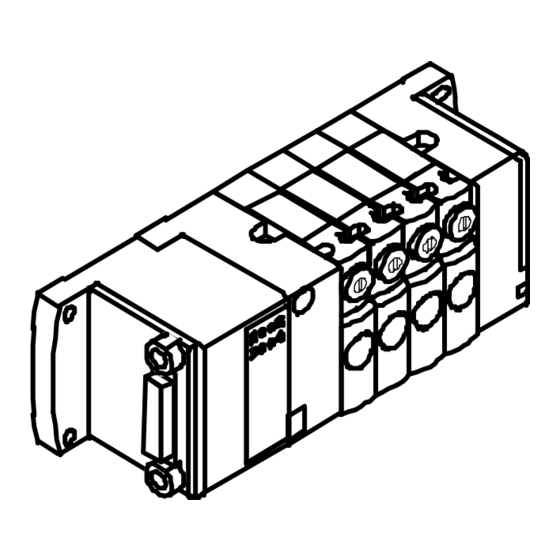
- Page 1 Compact performance - Smart cubic Pneumatics manual CPV-SC valve terminal Type CPVSC1-VI Manual 530 926 en 0112NH [659699]...
- Page 3 ....... . . 530 926 E (Festo AG & Co., D-73726 Esslingen, Federal Republic of Germany, 2001) Internet: http://www.festo.com...
- Page 4 Contents and general instructions Festo P.BE-CPVSC-EN en 0112NH...
-
Page 5: Table Of Contents
..........4-11 Festo P.BE-CPVSC-EN en 0112NH... - Page 6 ............Festo P.BE-CPVSC-EN en 0112NH...
-
Page 7: Designated Use
This manual is intended exclusively for technicians trained in control and automation technology, who have experience in fitting, installing, commissioning, servicing and converting pneumatic components. Service Please consult your local Festo service centre if you have any technical problems. Festo P.BE-CPVSC-EN en 0112NH... -
Page 8: Notes On This Manual
CPV-SC valve terminal. This manual describes only the pneumatic compo- nents and refers to the CPV-SC valve terminal with electric multipin connection. For information on the electrics/electronics see leaflet sup- plied with the product. Festo P.BE-CPVSC-EN en 0112NH... -
Page 9: Important User Instructions
This means that failure to observe this instruction may result in damage to property. The following pictogram marks passages in the text which describe activities with electrostatically sensitive compo- nents. Electrostatically sensitive components may be damaged if they are not handled correctly. Festo P.BE-CPVSC-EN en 0112NH... - Page 10 Accessories: Information on necessary or sensible accessories for the Festo product. Environment: Information on environment-friendly use of Festo products. Text markings The bullet indicates activities which may be carried out in • any order. 1. Figures denote activities which must be carried out in the numerical order specified.
-
Page 11: List Of Abbreviations
All valve solenoid coils are connected centrally via this connection. Separator plates Plate for dividing the valve terminal into pressure zones Valve block Basic unit with valve sub-base, blanking and end plates Valve plate Plate with single-solenoid or double-solenoid valve Festo P.BE-CPVSC-EN en 0112NH... - Page 12 Contents and general instructions Festo P.BE-CPVSC-EN en 0112NH...
-
Page 13: Summary Of Components
Summary of components Chapter 1 Festo P.BE-CPVSC-EN en 0112NH... - Page 14 ........Festo P.BE-CPVSC-EN en 0112NH...
-
Page 15: Description Of Variants
1. Summary of components Description of variants Festo assists you in solving your automation tasks at machine level with valve terminals. Due to its compact structure the CPV-SC valve terminal can be mounted close to the actuators to be controlled. Short compressed air tubing can therefore be used. - Page 16 Additional pressure supply Additional supply of compressed air (1) and additional exhaust removal (3/5) Blanking plate Plate without valve function for reserving a valve location Further information on the valve plates can be found in Appendix A. Festo P.BE-CPVSC-EN en 0112NH...
- Page 17 Left-hand end plate depending on vari- for reserving a valve location ant with connection 1 or 1 and 12/14 Valve sub-bases with single-solenoid or double-solenoid valves (double- solenoid valve occupies 2 valve locations) Fig. 1/1: Components of the CPV-SC valve terminal Festo P.BE-CPVSC-EN en 0112NH...
- Page 18 Manual override (per pilot solenoid, Work connections (2, 4) per valve locking and non-locking) Supply connections (1, 12/14) Exhaust connections (3/5, 82/84) Fig. 1/2: Pneumatic connecting and operating elements of the CPV-SC valve terminal Festo P.BE-CPVSC-EN en 0112NH...
- Page 19 Multipin connection with 20-pin Valve location identification label flat cable or 15-pin Sub-D multipin Yellow LED, signal status displays connection per pilot solenoid Fig. 1/3: Electrical connecting and display elements of the CPV-SC valve terminal with MP connection Festo P.BE-CPVSC-EN en 0112NH...
- Page 20 1. Summary of components Festo P.BE-CPVSC-EN en 0112NH...
-
Page 21: Fitting
Fitting Chapter 2 Festo P.BE-CPVSC-EN en 0112NH... - Page 22 ........Fitting the manual override cover (optional) ......Festo P.BE-CPVSC-EN en 0112NH...
-
Page 23: Fitting Variants
Fitting variants The CPV-SC valve terminal with individual tubing has already been prepared for integration in a system or machine for the following fitting variants: – Fitting onto a wall Festo P.BE-CPVSC-EN en 0112NH... -
Page 24: Fitting Onto A Wall
Valve locations 114 mm 33.2 mm 156 mm 198 mm Then fasten the CPV-SC valve terminal with four M3 • screws of sufficient length to the wall (tightening torque 0.6 + 0.2 Nm). Festo P.BE-CPVSC-EN en 0112NH... -
Page 25: Fitting The Manual Override Cover (Optional)
Covers can be fitted onto the manual override to protect it against unauthorized use. Proceed as follows: Clip the covers into the grooves in the manual override • (see diagram). Manual override Cover Fig. 2/1: Fitting the manual override cover Festo P.BE-CPVSC-EN en 0112NH... - Page 26 2. Fitting Festo P.BE-CPVSC-EN en 0112NH...
-
Page 27: Installation
Installation Chapter 3 Festo P.BE-CPVSC-EN en 0112NH... - Page 28 3-12 3.3.4 Connecting the electric cables ......3-15 Festo P.BE-CPVSC-EN en 0112NH...
-
Page 29: Installation
In this way you will avoid functional damage to the valves. A higher amount of residual oil cannot be permitted irrespec- tive of the compressor oil, as otherwise the basic lubricating oil will be washed out in the course of time. Festo P.BE-CPVSC-EN en 0112NH... -
Page 30: Operation With Lubricated Compressed Air
Incorrect additional oil and an excessive oil content in the compressed air will reduce the service life of the valve ter- minal. – Use the Festo special oil OFSW-32 or the alternative listed in the Festo Catalogue (as per DIN51524-HLP32, basic viscosity 32cST at 40° C). - Page 31 A further indication of excessive lubrication is the colouring or the status of the exhaust silencers. A clear yellowish disco- louring of the filter element or drops of oil on the silencers indicate that the lubricator is set too high. Festo P.BE-CPVSC-EN en 0112NH...
-
Page 32: General Connection Technology
Please note If necessary, place a suitable seal under each M5/M7 • screw connector or silencer in order to avoid leakage. – If elbow screw connectors or multiple distributors are used, the airflow will be reduced slightly. Festo P.BE-CPVSC-EN en 0112NH... - Page 33 – multiple hose holders. Removing 1. Loosen the locking screw or locking ring of the screw connector. 2. Pull out the tubing. 3. Replace non-required screw connectors with blanking plugs 3 . Connecting Removing Fig. 3/1: Tubing variants Festo P.BE-CPVSC-EN en 0112NH...
-
Page 34: Connecting The Cpv-Sc Valve Terminal
If the supply pressure of your CPV-SC valve terminal lies be- tween 3 and 8 bar, you can operate it with internally branched auxiliary pilot air. In this case the auxiliary pilot air will be taken from connection 1 in the left-hand end plate. Festo P.BE-CPVSC-EN en 0112NH... - Page 35 (see diagrams). Control pressure (connection 12/14), [bar] Supply pressure (connection 1), [bar] Fig. 3/2: Auxiliary pilot air diagram for valve plate with Ident code J Festo P.BE-CPVSC-EN en 0112NH...
-
Page 36: Pressure Zones
1 on the left-hand end plate; further pressure zones are supplied via connection 4 on the relevant separator plate. With separator plate with Ident. Code S, the exhaust air is removed via connection 2 on the separator plate (see dia- gram). 3-10 Festo P.BE-CPVSC-EN en 0112NH... - Page 37 If there are more than two valve functions per pressure zone, additional compressed air supply/exhausting may be required (additional pressure supply plate Ident. Code: U). This occupies one valve location. 3-11 Festo P.BE-CPVSC-EN en 0112NH...
-
Page 38: Connecting The Supply And Work Lines
Each valve has its own housing. The control valve is situated to the left of the “work valve” and does not have any work connections. Fit the screw connector or the silencers according to the table below. Then connect the pneumatic tubing. 3-12 Festo P.BE-CPVSC-EN en 0112NH... - Page 39 Exhausting the auxili- M5/QS4 Connections in the right- ary pilot air hand end plate – for ducted exhaust air – for silencers 2 or 4 Work air/vacuum M5/QS4/QS3 Screw connector Fig. 3/4: Assignment of connections 3-13 Festo P.BE-CPVSC-EN en 0112NH...
- Page 40 These connections must not be sealed with blanking plugs. Exhaust channels 3 and 5 are grouped together in the CPV- SC valve terminal. Separate exhaust restriction of channels 3 or 5 is not therefore possible. 3-14 Festo P.BE-CPVSC-EN en 0112NH...
-
Page 41: Connecting The Electric Cables
By the use of PELV power units, protection against electric shock (protection against direct and indirect contact) is guar- anteed with the Festo valve terminals in accordance with EN 60204-1/IEC 204. Safety transformers with the adjacent symbol must be used for supplying PELV networks. The valve terminals must be earthed to ensure that they function cor- rectly (e.g. - Page 42 Long signal cables reduce the immunity to interference. Do not exceed the maximum permitted signal cable length of 10 m. Detailed information on fitting the electrical connections can be found in the leaflet supplied with the product. 3-16 Festo P.BE-CPVSC-EN en 0112NH...
- Page 43 Commissioning Chapter 4 Festo P.BE-CPVSC-EN en 0112NH...
- Page 44 ..........4-11 Festo P.BE-CPVSC-EN en 0112NH...
-
Page 45: Commissioning
The slow increase in pressure of the complete supply does not then affect the cylinder. Depending on the valve function, the cylinder would extend or retract suddenly. Festo P.BE-CPVSC-EN en 0112NH... - Page 46 (12/14) valve Branched after the slow slow after pressure fast safety start-up increase with (1) valve Branched in front slow fast before pressure slow of the safety increase with (1) start-up valve Festo P.BE-CPVSC-EN en 0112NH...
-
Page 47: Testing The Valves
Complete commissioning of the Installing and connecting the complete system complete system. Program control via PLC/industrial PC Commissioning the pneumatic components by means of the manual override is described below. Festo P.BE-CPVSC-EN en 0112NH... - Page 48 The manual override has been designed to be used in locking or non-locking form. Method of actuation Method of operation Non-locking After actuation the manual over- ride is reset by a spring. Locking The manual override remains actuated until it is reset by hand. Festo P.BE-CPVSC-EN en 0112NH...
- Page 49 The assignment of the manual override actuations to the valves is as follows: Single-solenoid valves Double-solenoid valves (Ident. Code: D, N, K, M) (Ident. Code: J) Manual override to pilot solenoid 14 Manual override to pilot solenoid 12 Manual override to pilot solenoid 14 Festo P.BE-CPVSC-EN en 0112NH...
- Page 50 3. Make sure that all the valves are in their basic positions before commissioning the valve terminal. 4. Switch off the compressed air supply after checking the valves. Festo P.BE-CPVSC-EN en 0112NH...
- Page 51 12 of the relevant valve or apply current to pilot solenoid 12. Bring the locking manual override actuations into the • basic position again. In this way you will avoid undefined switching states when commissioning the machine/system. Festo P.BE-CPVSC-EN en 0112NH...
- Page 52 Use a blunt pencil for actuating the non-locking manual • override. Actuate the manual override at 8 bar only with max 25 N. • You will then avoid malfunctioning or damage to the man- ual override. 4-10 Festo P.BE-CPVSC-EN en 0112NH...
-
Page 53: Eliminating Faults
– Switch position After switching on again check the • operating pressure (e.g. pressure zones) – does not react – Basic position Servicing required • – Check the controller connection (apply pressure> 3 bar at controller) 4-11 Festo P.BE-CPVSC-EN en 0112NH... - Page 54 Slow start-up after EMERGENCY If there are control signals, the STOP auxiliary pilot air must be at full pressure immediately after being switched on. 4-12 Festo P.BE-CPVSC-EN en 0112NH...
- Page 55 (see diagram). LED for valve location 0 Valve location 3 Valve location 0 LED for valve location 3 Fig. 4/2: Assignment of LED to valve location 4-13 Festo P.BE-CPVSC-EN en 0112NH...
- Page 56 (21.6 V to 26.4 V DC) – Compressed air supply not OK. – Pilot exhaust blocked – Servicing required *) With double-solenoid valves the LED lights up only when the signal is present. 4-14 Festo P.BE-CPVSC-EN en 0112NH...
-
Page 57: Maintenance And Conversion
Maintenance and conversion Chapter 5 Festo P.BE-CPVSC-EN en 0112NH... - Page 58 ......Fitting/removing components in valve locations ..... . Festo P.BE-CPVSC-EN en 0112NH...
-
Page 59: Cleaning/Replacing The Large-Area Silencer
5. Fasten the silencer insert only with the original screws (see table). Fastening screws of the silencer insert Torx T6, strength class 10.9 Valve terminal Screw Tightening torque CPVSC1 M 2 x 5.5 0.4 + 0.1 Nm Festo P.BE-CPVSC-EN en 0112NH... -
Page 60: Fitting/Removing Components In Valve Locations
1. Loosen the multipin plug and disconnect it carefully. 2. Loosen the tubing at work connections 2 and 4 of the valve sub-base to be replaced (see section 3.2 “General connection methods”). 3. Loosen the wall fastening on the right-hand end plate. Festo P.BE-CPVSC-EN en 0112NH... - Page 61 2 mm gap to the left and right of the component to be replaced Tie rod Fig. 5/1: Loosening the tie rods 3. When the double-solenoid valve Ident. code J is removed, both valve plates and the ”control” and ”work valves” must also be removed. Festo P.BE-CPVSC-EN en 0112NH...
- Page 62 Fitting a component Please note The valve with the work connection sub-base is a unit tested for leakage by Festo. – Do not disconnect the screw connectors in the work connection sub-base. They guarantee that the unit does not leak.
- Page 63 Fig. 5/3: Fitting a component in a valve location 4. Align the CPV-SC valve terminal components on a flat sur- face so that they are not offset. 5. Tighten the tie rods with 0.8 + 0.2 Nm. Festo P.BE-CPVSC-EN en 0112NH...
- Page 64 5. Maintenance and conversion Fitting the CPV-SC valve terminal Fasten the right-hand wall fastening with two M3 screws • of sufficient length to the wall. Complete the pneumatic and electric connections (see • chapter 3). Festo P.BE-CPVSC-EN en 0112NH...
- Page 65 Technical appendix Appendix A Festo P.BE-CPVSC-EN en 0112NH...
-
Page 66: A. Technical Appendix
......... . Festo P.BE-CPVSC-EN en 0112NH... -
Page 67: Technical Appendix
Flat cable with round conductors in grid 1.27 mm, Cable cross-sectional area 0.13 mm (AWG26) – Plug connector for flat band cable Unused plug connector form C with strain relief, with 20 sockets with insulation-piercing connection, contact sur- face gold ICE60603-13-C020FD-7C1E-2 Festo P.BE-CPVSC-EN en 0112NH... -
Page 68: Technical Specifications
Large fastening screws – For fastening onto a wall M3 (length of screw depends on the features of the fastening surface) Materials – End plates, electrical sub-base PAXMD6-GF50 – Seal – Valve housing – Power connection plates PA66-GF30 Festo P.BE-CPVSC-EN en 0112NH... - Page 69 12/14). Otherwise observe the instructions in the section ”Preparing the compressed air.” – With CPV-SC valve terminals with internally branched auxiliary pilot air, the above mentioned remark also applies to the supply air (connection 1). Festo P.BE-CPVSC-EN en 0112NH...
- Page 70 12/14), [bar] Supply pressure (connection 1), [bar] Fig. A/4: Auxiliary pilot air diagram for valve plate with Ident code J Please note The fitted pneumatic screw connectors cause a reduction in the flow rate of the valves. Festo P.BE-CPVSC-EN en 0112NH...
- Page 71 24 V DC – Tolerance ± 10 % (21.6 V...26.4 V DC) Power consumption (at 24 V, on the multipin plug) – Per valve solenoid coil 1) The maximum permitted signal cable length is 10 m. Festo P.BE-CPVSC-EN en 0112NH...
- Page 72 A. Technical appendix Please note Data on the electrics of the CPV-SC valve terminal with multipin connection are enclosed with the product. Festo P.BE-CPVSC-EN en 0112NH...
-
Page 73: Overview Of End Plates
Method of operation – Two single-solenoid 2/2-way valves blocked in basic position, pneumatic spring reset 12/14 Ident. Code N 82/84 Method of operation – Two single-solenoid 3/2-way valves open in basic position, pneumatic spring reset 12/14 Festo P.BE-CPVSC-EN en 0112NH... - Page 74 The double-solenoid valve consists of two valve plates: the control valve and the work valve. The control valve is marked on the front with j 12; the work valve is marked with Ident. code J. 12/14 A-10 Festo P.BE-CPVSC-EN en 0112NH...
- Page 75 Index Appendix B Festo P.BE-CPVSC-EN en 0112NH...
-
Page 76: B. Index
............Festo P.BE-CPVSC-EN en 0112NH... -
Page 77: B.1 Index
........Display elements, CPV-SC valve terminal with MP connection ..Festo P.BE-CPVSC-EN en 0112NH... - Page 78 MP connection ........Festo P.BE-CPVSC-EN en 0112NH...
- Page 79 ......Switching status display ......4-14 Festo P.BE-CPVSC-EN en 0112NH...
- Page 80 ........Festo P.BE-CPVSC-EN en 0112NH...
Need help?
Do you have a question about the Smart cubic CPV-SC Series and is the answer not in the manual?
Questions and answers