Table of Contents
Advertisement
Advertisement
Table of Contents
Troubleshooting

Related Manuals for Molecular Devices SpectraMax Paradigm


Summary of Contents for Molecular Devices SpectraMax Paradigm
- Page 1 SpectraMax® Paradigm® Multi-Mode Detection Platform User Guide 5014038 E May 2015...
- Page 2 For research use only. Not for use in diagnostic procedures. The trademarks mentioned herein are the property of Molecular Devices, LLC or their respective owners. These trademarks may not be used in any type of promotion or advertising without the prior written permission of Molecular Devices, LLC.
-
Page 3: Table Of Contents
Contents Safety Information Warnings, Cautions, Notes, and Tips Symbols on Instrument Labels Before Operating the Instrument Electrical Safety Laser Safety Chemical and Biological Safety Moving Parts Safety Cleaning and Maintenance Safety Chapter 1: Introduction Applications Dual Photomultiplier Tubes Microplate Controls Environmental Controls Chapter 2: Read Modes and Read Types Supported Read Types... - Page 4 SpectraMax Paradigm Multi-Mode Detection Platform User Guide Connecting and Disconnecting a Gas Supply Chapter 4: Using the Instrument Front Panel Controls and Indicators Turning the Instrument On and Off Using Detection Cartridges Loading and Unloading Microplates Chapter 5: Available Detection Cartridges...
- Page 5 Appendix B: System Diagrams and Dimensions Appendix C: Electromagnetic Compatibility Glossary Index 5014038 E...
- Page 6 SpectraMax Paradigm Multi-Mode Detection Platform User Guide 5014038 E...
-
Page 7: Safety Information
When warnings and cautions are displayed in this guide, be careful to follow the specific safety information related to them. The following user-attention statements can be displayed in the text of Molecular Devices user documentation. Each statement implies a particular level of observation or... -
Page 8: Symbols On Instrument Labels
For products under the requirement of the WEEE directive, please contact your dealer or local Molecular Devices office for the procedures to facilitate the proper collection, treatment, recovery, recycling, and safe disposal of the device. -
Page 9: Before Operating The Instrument
To ensure sufficient ventilation and provide access for disconnecting power from the instrument, maintain a 20 cm to 30 cm (7.9 in. to 11.8 in.) gap between the rear of the instrument and the wall. Molecular Devices recommends turning the power off when the instrument is not in use. 5014038 E... -
Page 10: Laser Safety
SpectraMax Paradigm Multi-Mode Detection Platform User Guide Laser Safety WARNING! LASER LIGHT. This symbol indicates that a potential hazard to personal safety exists from a laser source. When this symbol is displayed in this guide, be careful to follow to the specific safety information related to the symbol. -
Page 11: Chemical And Biological Safety
Safety Information Chemical and Biological Safety Normal operation of the instrument can involve the use of materials that are toxic, flammable, or otherwise biologically harmful. When using such materials, observe the following precautions: Handle infectious samples based on good laboratory procedures and methods to prevent the spread of disease. -
Page 12: Moving Parts Safety
SpectraMax Paradigm Multi-Mode Detection Platform User Guide Moving Parts Safety To prevent injury due to moving parts, observe the following: Never try to exchange labware, reagents, or tools while the instrument is operating. Never try to physically restrict the moving components of the instrument. -
Page 13: Cleaning And Maintenance Safety
Review the Chemical and Biological Safety information contained in this guide. Do only the maintenance described in this guide. Maintenance procedures other than those specified in this guide can be done only by Molecular Devices qualified personnel. See Obtaining Support on page 165. - Page 14 SpectraMax Paradigm Multi-Mode Detection Platform User Guide 5014038 E...
-
Page 15: Chapter 1: Introduction
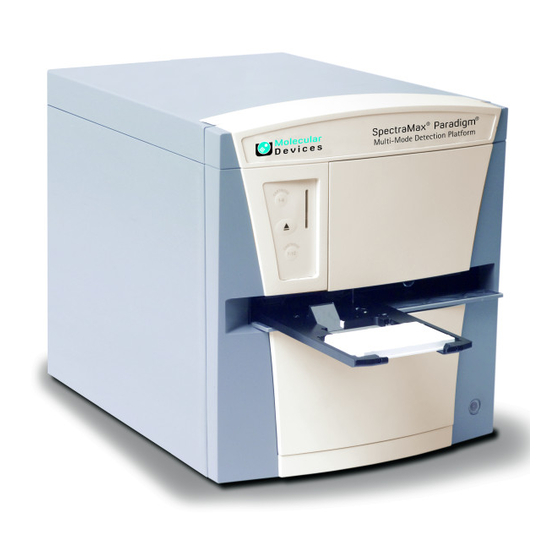
Chapter 1: Introduction The SpectraMax® Paradigm® Multi-Mode Detection Platform from Molecular Devices® is a user-upgradeable, multi-mode microplate reader capable of performing absorbance, fluorescence, time-resolved fluorescence (including HTRF), fluorescence polarization, AlphaScreen®, AlphaLISA®, and luminescence measurements. An external computer running the SoftMax® Pro provides integrated instrument control, data display, and statistical data analysis. -
Page 16: Applications
Typical applications include ELISA, nucleic acid, protein, enzymatic type homogeneous and heterogeneous assays, microbial growth, endotoxin testing, and pipettor calibration. Application notes with specific application protocol suggestions can be found in the Information Center and the Knowledge Base on the Molecular Devices web site at www.moleculardevices.com. Dual Photomultiplier Tubes The SpectraMax Paradigm Instrument is equipped with two photo multiplier tubes (PMTs). - Page 17 Chapter 1: Introduction On-the-Fly Detection With some detection cartridges, the instrument can read microplates as the microplate drawer is moving within the chamber instead of pausing the microplate drawer to read each well. This results in shorter read times. There are two On-the-Fly Detection modes: Selecting Performance results in a faster read time than not using On-the-Fly Detection, but not as fast as the Speed mode.
-
Page 18: Environmental Controls
If you use the instrument to warm the samples, Molecular Devices recommends that you use a seal or lid on the microplate to prevent evaporation of the sample. Using a seal or lid also helps to maintain uniform temperature. -
Page 19: Chapter 2: Read Modes And Read Types
Application notes with specific application protocol suggestions can be found in the Information Center and the Knowledge Base on the Molecular Devices web site at www.moleculardevices.com. For more information on the supported read modes, see the following topics:... - Page 20 SpectraMax Paradigm Multi-Mode Detection Platform User Guide Endpoint Read Type In an Endpoint read, a reading of each microplate well is taken in the center of each well, at a single wavelength or at multiple wavelengths. Depending on the read mode, raw data values are reported as optical density (OD), %Transmittance (%T), relative fluorescence units (RFU), or relative luminescence units (RLU).
- Page 21 Chapter 2: Read Modes and Read Types Well Scan Read Type A Well Scan read can take readings at more than one location within a well. A Well Scan read takes one or more readings of a single well of a microplate on an evenly spaced grid inside of each well at single or multiple wavelengths.
- Page 22 The selected area is read, and a TIFF image is generated with the results of the read. The Molecular Devices ScanLater™ Western Blot Assay Kit is a novel system for protein analysis that is incorporated into a SpectraMax Paradigm Multi-Mode Detection Platform.
-
Page 23: Absorbance Read Mode
The reported OD values for turbid samples are likely to be different when read by different instruments. For optimum results, Molecular Devices recommends that you run replicates for all blanks, controls, and samples. In this case, the blank value that can be subtracted is the average value of all blanks. - Page 24 You can use the Protocol Manager in the SoftMax Pro Software to quickly find and open a predefined protocol. More protocols and updated protocols can be downloaded from the Knowledge Base on the Molecular Devices support web site (www.moleculardevices.com/support) or from the protocol sharing web site (www.softmaxpro.org). PathCheck Pathlength Measurement Technology The temperature-independent PathCheck®...
- Page 25 Chapter 2: Read Modes and Read Types In a microplate, pathlength is dependent on the liquid volume, so absorbance is proportional to both the concentration and the pathlength of the sample. Standard curves are often used to determine analyte concentrations in vertical-beam photometry of unknowns, yet errors can still occur from pipetting the samples and standards.
- Page 26 SpectraMax Paradigm Multi-Mode Detection Platform User Guide Eliminating the Pathlength-Independent Component Raw OD measurements of microplate samples include both pathlength-dependent components (sample and solvent) and a pathlength-independent component (OD of microplate material). The pathlength-independent component must be eliminated from the calculation to get valid results that have been normalized by the PathCheck technology.
- Page 27 Chapter 2: Read Modes and Read Types Interfering Substances Material that absorbs in the 900 nm to 1000 nm spectral region could interfere with PathCheck technology measurements. Fortunately, there are few materials that do interfere at the concentrations generally used. Turbidity is the most common interference. If you can detect turbidity in your sample, you should not use the PathCheck technology.
-
Page 28: Fluorescence Intensity Read Mode
SpectraMax Paradigm Multi-Mode Detection Platform User Guide Fluorescence Intensity Read Mode Fluorescence occurs when absorbed light is re-radiated at a longer wavelength. In the Fluorescence Intensity (FL) read mode, the instrument measures the intensity of the re- radiated light and expresses the result in Relative Fluorescence Units (RFU). - Page 29 Chapter 2: Read Modes and Read Types Tip: If the Stokes shift is small, you should choose an excitation wavelength that is as far away from the emission maximum as possible while still being capable of stimulating the fluorophore so that less of the excited light overlaps the emission spectrum, permitting better selection and quantitation of the emitted light.
- Page 30 More protocols and updated protocols can be downloaded from the Knowledge Base on the Molecular Devices support web site (www.moleculardevices.com/support) or from the protocol sharing web site (www.softmaxpro.org). The following detection cartridges have fluorescence intensity read mode capability:...
- Page 31 (sample – blank) / (slope of standard curve). For optimum results, Molecular Devices recommends that you run replicates for all blanks, controls, and samples. In this case, the blank value that can be subtracted is the average value of all blanks.
- Page 32 SpectraMax Paradigm Multi-Mode Detection Platform User Guide Detection Limit The detection limit is the smallest sample concentration that can be measured reliably above the blank. Determining the detection limit requires taking a number of blank measurements and calculating an average value and standard deviation for the blanks. The detection threshold is defined as the average blank plus three standard deviations.
-
Page 33: Luminescence Read Mode
To help eliminate background luminescence from a microplate that has been exposed to light, Molecular Devices recommends dark adaptation of the microplate by placing the sample-loaded microplate in the instrument for several minutes before starting the read. - Page 34 You can use the Protocol Manager in the SoftMax Pro Software to quickly find and open a predefined protocol. More protocols and updated protocols can be downloaded from the Knowledge Base on the Molecular Devices support web site (www.moleculardevices.com/support) or from the protocol sharing web site (www.softmaxpro.org). The following detection cartridges have luminescence read mode capability:...
- Page 35 For optimum results, Molecular Devices recommends that you run replicates for all blanks, controls, and samples. In this case, the blank value that can be subtracted is the average value of all blanks.
- Page 36 SpectraMax Paradigm Multi-Mode Detection Platform User Guide Detection Limit The detection limit is the smallest sample concentration that can be measured reliably above the blank. Determining the detection limit requires taking a number of blank measurements and calculating an average value and standard deviation for the blanks. The detection threshold is defined as the average blank plus three standard deviations.
- Page 37 Chapter 2: Read Modes and Read Types Data Optimization The measurement noise is dependent on the read time per sample (time per plate or time per well). In particular, the detection limit improves when the read time is increased. Therefore, it is important to specify the read time when comparing measurements. All low-light-level detection devices have some measurement noise in common.
-
Page 38: Time-Resolved Fluorescence Read Mode
SpectraMax Paradigm Multi-Mode Detection Platform User Guide Time-Resolved Fluorescence Read Mode Time-resolved fluorescence (TRF) is a measurement technique that depends on three characteristics that lead to better discrimination between the specific signal, proportional to the quantity of label, and the unspecific fluorescence resulting from background and... - Page 39 For optimum results, Molecular Devices recommends that you run replicates for all blanks, controls, and samples. In this case, the blank value that can be subtracted is the average value of all blanks.
- Page 40 SpectraMax Paradigm Multi-Mode Detection Platform User Guide Data Normalization TRF raw data changes in magnitude when the timing parameters are changed. However, TRF data are normalized for a number of 1000 pulses. This means that the sample raw data does not change when only the number of pulses is changed.
- Page 41 Chapter 2: Read Modes and Read Types Table 2-1: Time-resolved fluorescence timing parameters example Parameter Value Comment Pulse length 0.100 ms The period for excitation of the sample, shown as t in the following figure. This is the suggested value for the TUNE, MULTI, and TRF detection cartridges.
- Page 42 SpectraMax Paradigm Multi-Mode Detection Platform User Guide When neglecting the time delay t compared to the integration time window t , the accumulated signal A can be approximated with the following equation: A / A = (1 – exp(–M)) x 100% In the previous equation, M is the size of the time window (or integration time) divided by the exponential decay time constant (or the fluorescence lifetime of the label).
- Page 43 Chapter 2: Read Modes and Read Types Suggested timing parameters for a dual-label Europium-Samarium measurement are listed in the following table. Table 2-3: Time-resolved fluorescence timing parameters for dual-label Europium- Samarium Parameter Value Comment Pulse length 0.100 ms The time interval for flash monitoring This is the suggested value for the TRF detection cartridge.
-
Page 44: Fret Read Mode
You can use the Protocol Manager in the SoftMax Pro Software to quickly find and open a predefined protocol. More protocols and updated protocols can be downloaded from the Knowledge Base on the Molecular Devices support web site (www.moleculardevices.com/support) or from the protocol sharing web site (www.softmaxpro.org). The following detection cartridge has FRET read mode capability:... -
Page 45: Htrf Read Mode
Chapter 2: Read Modes and Read Types HTRF Read Mode Homogeneous time-resolved fluorescence (HTRF) is a measurement technique based on fluorescence resonance energy transfer (FRET) using the advantages of time-resolved fluorescence (TRF) reading. Fluorescence resonance energy transfer (FRET) is a distance-dependent interaction between the electronic excited states of two dye molecules in which excitation is transferred from a donor molecule to an acceptor molecule without emission of a photon. - Page 46 The fluorescence ratio related to the HTRF readout is a correction method developed by Cisbio, for which Cisbio has granted a license to Molecular Devices. Its application is strictly limited to the use of HTRF reagents and technology, excluding other TR-FRET technologies such as IMAP TR-FRET calculations of acceptor to donor ratios.
- Page 47 Chapter 2: Read Modes and Read Types Data Reduction Data reduction for HTRF reads consists of two steps. First, a ratio of the signal measured by the emission from the acceptor label at 665 nm to the signal measured by the emission of the donor label at 616 nm is calculated and multiplied by a factor of 10,000.
- Page 48 SpectraMax Paradigm Multi-Mode Detection Platform User Guide The second timing parameter which can be optimized is the Integration time per cycle. Care must be taken in optimizing the integration time to consider noise. Delta F is higher at low integration times, but noise is also high at low integration times. The optimum integration time is where noise is minimized while maximizing Delta F.
-
Page 49: Fluorescence Polarization Read Mode
Chapter 2: Read Modes and Read Types Z´ is the standard statistical parameter in the high-throughput screening community for measuring the quality of a screening assay independent of test compounds. It is used as a measure of the signal separation between the positive controls and the negative controls in an assay. - Page 50 More protocols and updated protocols can be downloaded from the Knowledge Base on the Molecular Devices support web site (www.moleculardevices.com/support) or from the protocol sharing web site (www.softmaxpro.org). The following detection cartridges have fluorescence polarization read mode capability:...
- Page 51 For optimum results, Molecular Devices recommends that you run replicates for all blanks, controls, and samples. In this case, the blank value that can be subtracted is the average value of all blanks.
- Page 52 SpectraMax Paradigm Multi-Mode Detection Platform User Guide Data Qualification and Validation When validating the data of a fluorescence polarization measurement and the assay, the two factors to look at are the precision value and the Z´ parameter. The FP precision value is a measure of replicate uniformity determined by the standard deviation of replicates at a label concentration of 1 nM.
-
Page 53: Alphascreen Read Mode
Chapter 2: Read Modes and Read Types AlphaScreen Read Mode ALPHA stands for Amplified Luminescent Proximity Homogeneous Assay. AlphaScreen® is a bead-based chemistry used to study molecular interactions between moieties A and B, for example. When a biological interaction between A and B moves beads (coated with A and B, respectively) together, a cascade of chemical reactions produce a greatly amplified signal. - Page 54 You can use the Protocol Manager in the SoftMax Pro Software to quickly find and open a predefined protocol. More protocols and updated protocols can be downloaded from the Knowledge Base on the Molecular Devices support web site (www.moleculardevices.com/support) or from the protocol sharing web site (www.softmaxpro.org). To do AlphaScreen reads, the instrument requires...
- Page 55 Do not use an empty well for a blank. For optimum results, Molecular Devices recommends that you run replicates for all blanks, controls, and samples. In this case, the blank value that can be subtracted is the average value of all blanks.
- Page 56 SpectraMax Paradigm Multi-Mode Detection Platform User Guide Data Qualification and Validation Z´ is the standard statistical parameter in the high-throughput screening community for measuring the quality of a screening assay independent of test compounds. It is used as a measure of the signal separation between the positive controls and the negative controls in an assay.
-
Page 57: Western Blot Trf Read Mode
Western Blots. The Molecular Devices ScanLater™ Western Blot Assay Kit is a novel system for protein analysis that is incorporated into a SpectraMax Paradigm Multi-Mode Detection Platform. - Page 58 The SoftMax Pro Software comes with an installed version of the ImageJ software from U.S. National Institute of Health (NIH). For best results, use the Molecular Devices ScanLater™ Western Blot Assay Kit that matches your application.
- Page 59 Handling the Membrane To scan the membrane in a SpectraMax Paradigm Multi-Mode Detection Platform, the membrane must be placed in a Molecular Devices ScanLater™ Membrane Holder. See Loading the Membrane into the Membrane Holder on page 143. Note: Handle membranes by their edges only, using clean forceps. Do not touch the membrane with gloved or bare hands.
- Page 60 SpectraMax Paradigm Multi-Mode Detection Platform User Guide 5014038 E...
-
Page 61: Chapter 3: Unpacking And Setting Up The Instrument
Chapter 3: Unpacking and Setting Up the Instrument Before unpacking and setting up the SpectraMax Paradigm Multi-Mode Detection Platform, prepare a dry, flat work area that has sufficient space for the instrument, host computer, and required cables. See Instrument Specifications on page 167. -
Page 62: Contents Of The Package
SpectraMax Paradigm Multi-Mode Detection Platform User Guide Contents of the Package The package contains the instrument and the tools and accessories included in the accessory tool box and that are required for installing the instrument as follows: Table 3-1: Package Contents... -
Page 63: Unpacking The Instrument
Chapter 3: Unpacking and Setting Up the Instrument Unpacking the Instrument The packaging is specifically designed to protect the SpectraMax Paradigm Instrument during transportation. Transport locks are placed on the detection cartridge drawers, the photomultiplier tube (PMT) shutter, and the microplate drawer to protect the instrument from damage during shipping. - Page 64 SpectraMax Paradigm Multi-Mode Detection Platform User Guide To unpack the instrument: 1. Check the box for visible damage that occurred during transportation. In case of damage, inform the supplier immediately and keep the damaged packaging. CAUTION! Keep the box upright. Do not tip or tilt the box or place it on its side.
- Page 65 Chapter 3: Unpacking and Setting Up the Instrument 3. Grasp the handle on the cardboard and slide the instrument out of the box. Tip: It might be easier if a second person holds the box in place while the instrument is slid out on the cardboard. Figure 3-2: Sliding the Instrument Out of the Box 5014038 E...
- Page 66 SpectraMax Paradigm Multi-Mode Detection Platform User Guide 4. Remove the accessory tool box. Figure 3-3: The Instrument, the Accessories Toolbox, and the Foam Packing Item Description 1 Accessory Tool Box 2 SpectraMax Paradigm Multi-Mode Detection Platform CAUTION! Keep the instrument upright and level when lifting. Do not tip or shake the instrument to prevent damage to the moving components inside the instrument.
-
Page 67: Removing The Transport Locks
Chapter 3: Unpacking and Setting Up the Instrument 8. Gently return the instrument to the ground. 9. Remove the large plastic bag from the instrument. It might be necessary to slightly lift the instrument to get the bag over the feet. 10. - Page 68 SpectraMax Paradigm Multi-Mode Detection Platform User Guide To remove the transport locks: 1. Firmly pull on the top front cover to remove it and then set it aside. The top front cover is held onto the front of the instrument by powerful magnets.
- Page 69 Chapter 3: Unpacking and Setting Up the Instrument Figure 3-5: PMT Shutter and Detection Cartridge Drawer Transport Locks Item Description 1 PMT shutter transport lock 2 Top detection cartridge drawer 3 Top detection cartridge drawer transport lock 4 Bottom detection cartridge drawer 5 ...
- Page 70 SpectraMax Paradigm Multi-Mode Detection Platform User Guide Figure 3-6: Detection Cartridge Drawer Transport Lock Item Description 1 Top detection cartridge drawer 2 Top detection cartridge drawer transport lock 3 Bottom detection cartridge drawer 4 Bottom detection cartridge drawer transport lock 6.
- Page 71 Chapter 3: Unpacking and Setting Up the Instrument 13. Gently pull the yellow tab protruding from the microplate chamber door to open the door. The microplate drawer door must be held open manually while removing the transport lock. Note: Be careful not to tear the yellow tab. It must remain attached to the transport lock to make it easier to open the microplate chamber door.
-
Page 72: Connecting The Instrument Cables
SpectraMax Paradigm Multi-Mode Detection Platform User Guide Connecting the Instrument Cables The power cords and USB cables connect to the ports on the rear of the instrument. This procedure requires the following tools and accessories: Table 3-4: Required Tools and Accessories... - Page 73 Chapter 3: Unpacking and Setting Up the Instrument Figure 3-8: Power Switch, Fuses, and Connection Ports Item Description 1 USB port 2 Gas inlet quick-connect fitting 3 Power switch 4 Fuse carrier 5 Power port To connect the instrument cables: 1.
- Page 74 SpectraMax Paradigm Multi-Mode Detection Platform User Guide 4. Install the SoftMax Pro Software on the computer. See the SoftMax Pro Software installation guide or user guide. Note: The instrument is supported by version 6.0 or later. 5. Connect one end of the supplied USB cable to one of the USB ports on the computer, and then connect the other end of the USB cable to the USB port on the rear of the instrument.
-
Page 75: Unlocking The Spectramax Paradigm Instrument
Chapter 3: Unpacking and Setting Up the Instrument Unlocking the SpectraMax Paradigm Instrument When a SpectraMax Paradigm Instrument is first installed, the hardware transport locks need to be removed. As a safety precaution, internal locks controlled by the software prevent the drawers from opening until the instrument is detected and initialized by the SoftMax Pro Software. -
Page 76: Connecting And Disconnecting A Gas Supply
SpectraMax Paradigm Multi-Mode Detection Platform User Guide Note: If the instrument does not show in the Available Instruments list of the Instrument Connection dialog, then click Refresh above the list. 8. Follow the on-screen instructions in the Instrument Unlocking Procedure wizard to unlock the drawers and initialize the instrument. - Page 77 Chapter 3: Unpacking and Setting Up the Instrument Figure 3-9: Power Switch, Fuses, and Connection Ports Item Description 1 USB port 2 Gas inlet quick-connect fitting 3 Power switch 4 Fuse carrier 5 Power port WARNING! Use a compressed gas supply in a well-ventilated area. The instrument is not air-tight, and so gas can escape into the atmosphere surrounding the instrument.
- Page 78 SpectraMax Paradigm Multi-Mode Detection Platform User Guide To connect a gas supply to the instrument: 1. Make sure that the power switch on the rear of the instrument is in the off position. 2. Using a slot-head screwdriver, pry off the small black cap on the rear of the instrument along the right edge to access the quick-connect fitting.
-
Page 79: Chapter 4: Using The Instrument
Chapter 4: Using the Instrument Before operating the instrument or doing maintenance operations, make sure that you are familiar with the Safety Information on page 7 and make sure it is set up as instructed in Unpacking and Setting Up the Instrument on page For information on controlling the instrument with the software, see the SoftMax Pro Software application help or user guide. -
Page 80: Front Panel Controls And Indicators
SpectraMax Paradigm Multi-Mode Detection Platform User Guide Front Panel Controls and Indicators The front panel of the SpectraMax Paradigm Instrument has LED status indicators that provide information about instrument status, and a key pad that gives you hardware-based controls for opening and closing the detection cartridge drawers and the microplate drawer. - Page 81 Chapter 4: Using the Instrument Status Indicators The color and activity of the LED status indicators on the front of the instrument provide information about the instrument status. Table 4-2: LED Status Indicators Color Bar Activity Instrument Status Green LED is glowing solidly. The instrument is in the ready state.
-
Page 82: Turning The Instrument On And Off
SpectraMax Paradigm Multi-Mode Detection Platform User Guide Turning the Instrument On and Off The power switch and power connection are on the rear of the instrument. Figure 4-1: Power Switch, Fuses, and Connection Ports Item Description 1 USB port 2 ... - Page 83 Chapter 4: Using the Instrument To turn the instrument on or off, press the power switch to place the rocker in the on or off position. Table 4-3: Power Switch Item Description 1 Power switch 2 3 Before connecting or disconnecting the power cord, make sure that the power switch on the rear of the instrument is in the Off position.
-
Page 84: Using Detection Cartridges
Application notes with specific application protocol suggestions can be found in the Information Center and the Knowledge Base on the Molecular Devices web site at www.moleculardevices.com. A detection cartridge can occupy one or more positions, depending on size and functionality. - Page 85 Chapter 4: Using the Instrument To install a detection cartridge: 1. Press the TOP READ button on the front panel to open the top detection cartridge drawer, or press the BOTTOM READ button on the front panel to open the bottom detection cartridge drawer.
- Page 86 SpectraMax Paradigm Multi-Mode Detection Platform User Guide Figure 4-3: Top View of Detection Cartridge Drawer Item Description 1 Holder pin 2 Holder pin 3 Detection cartridge connector 4 Retaining rod 5 Retaining rod 5. Gently but firmly push the detection cartridge onto the holder pins and connector so that the detection cartridge is fully seated in the detection cartridge slot.
- Page 87 Chapter 4: Using the Instrument Figure 4-4: Detection Cartridge Retaining Clips and Retaining Rods Item Description 1 Detection cartridge 2 Retaining clip unattached 3 Retaining clip attached 4 Retaining rod 5 Retaining rod 7. Install more detection cartridges, if desired. 8.
- Page 88 SpectraMax Paradigm Multi-Mode Detection Platform User Guide Removing a Detection Cartridge It is not necessary to remove a detection cartridge when it is not in use. You can, however, remove a detection cartridge to make room for other detection cartridges or when the instrument is being packed for shipping.
- Page 89 Chapter 4: Using the Instrument Figure 4-5: Detection Cartridge Retaining Clips and Retaining Rods (continued) Item Description 4 Retaining rod 5 Retaining rod 2. Place the end of a slot-head screwdriver in the slot on the retaining clip and use it as a lever to unfasten the retaining clips on either side of the detection cartridge.
-
Page 90: Loading And Unloading Microplates
SpectraMax Paradigm Multi-Mode Detection Platform User Guide Loading and Unloading Microplates To load or unload a microplate: 1. On the front panel of the instrument, press the load/eject button to move the microplate drawer outside of the instrument. 2. Place the microplate on or remove it from the microplate drawer. - Page 91 Chapter 4: Using the Instrument Microplate Orientation Insert the microplate in the orientation that matches the orientation selected in the software. See the SoftMax Pro Software application help or user guide. Landscape puts the A1 location in the upper-left corner closest to the instrument. Portrait puts the A1 location in the upper-right corner closest to the instrument.
- Page 92 SpectraMax Paradigm Multi-Mode Detection Platform User Guide 5014038 E...
-
Page 93: Chapter 5: Available Detection Cartridges
Application notes with specific application protocol suggestions can be found in the Information Center and the Knowledge Base on the Molecular Devices web site at www.moleculardevices.com. For information about the supported detection cartridges, see the following topics:... -
Page 94: Absorbance Detection Cartridge
You can use the Protocol Manager in the SoftMax Pro Software to quickly find and open a predefined protocol. More protocols and updated protocols can be downloaded from the Knowledge Base on the Molecular Devices support web site (www.moleculardevices.com/support) or from the protocol sharing web site (www.softmaxpro.org). 5014038 E... - Page 95 Table 5-1: Microplate Selection Guidelines for the Absorbance Detection Cartridge Read Mode Microplate Type Other Considerations Absorbance all clear, clear bottom, When an application specifies a surface treatment, use (ABS) UV clear, flat bottom only microplates with the correct treatment. Molecular Devices recommends using an unlidded plate for absorbance measurements. 5014038 E...
- Page 96 SpectraMax Paradigm Multi-Mode Detection Platform User Guide Measurement Specifications The specifications for measurements using the Absorbance Detection Cartridge are shown in the following table. Table 5-2: Measurement Specifications for the Absorbance Detection Cartridge Item Description Detection cartridge name Absorbance Detection Cartridge...
-
Page 97: Tunable Wavelength (Tune) Detection Cartridge
For installation instructions, see Installing a Detection Cartridge on page Note:Molecular Devices recommends that you install the Tunable Wavelength (TUNE) Detection Cartridge in the top detection cartridge drawer when running time-resolved fluorescence or glow luminescence read modes. - Page 98 SpectraMax Paradigm Multi-Mode Detection Platform User Guide About Fluorescence Intensity In fluorescence intensity read mode, the source light is directed through a tunable excitation filter and then focused by an objective lens from above or below the microplate. The filter passes only the specified wavelength band necessary to excite samples.
- Page 99 Chapter 5: Available Detection Cartridges About Time-Resolved Fluorescence Time-resolved fluorescence (TRF) is a measurement technique that depends on three characteristics that lead to better discrimination between the specific signal, proportional to the quantity of label, and the unspecific fluorescence resulting from background and compound interference: Pulsed excitation light sources Time-gated electronics faster than the fluorescence lifetime...
- Page 100 SpectraMax Paradigm Multi-Mode Detection Platform User Guide Microplate Recommendations The following information is specific to this detection cartridge. For general microplate selection and handling guidelines, see Selecting Suitable Microplate Types on page Table 5-3: Microplate Selection Guidelines for the Tunable Wavelength (TUNE) Detection...
- Page 101 Chapter 5: Available Detection Cartridges Table 5-4: Measurement Specifications for the Tunable Wavelength (TUNE) Detection Cartridge (continued) Item Description Luminescence (LUM) Type Single emission Number of slots 3 slots, top or bottom Light source High-power LEDs Wavelength range EX: 360 nm to 790 nm EM: 400 nm to 850 nm Wavelength Increment: 1 nm Wavelength Accuracy: ±2 nm...
-
Page 102: Multi-Mode (Multi) Detection Cartridge
For installation instructions, see Installing a Detection Cartridge on page Note:Molecular Devices recommends that you install the Multi-Mode (MULTI) Detection Cartridge in the top detection cartridge drawer when running time-resolved fluorescence or glow luminescence read modes. - Page 103 Chapter 5: Available Detection Cartridges About Fluorescence Intensity In fluorescence intensity read mode, the source light is directed through a tunable excitation filter and then focused by an objective lens from above or below the microplate. The filter passes only the specified wavelength band necessary to excite samples. The objective lens collects the resulting fluorescence and directs it through an emission filter to separate background light from the specific wavelengths generated by samples.
- Page 104 SpectraMax Paradigm Multi-Mode Detection Platform User Guide About Time-Resolved Fluorescence Time-resolved fluorescence (TRF) is a measurement technique that depends on three characteristics that lead to better discrimination between the specific signal, proportional to the quantity of label, and the unspecific fluorescence resulting from background and...
- Page 105 Solid white When an application specifies a surface treatment, use only microplates with the correct treatment. Molecular Devices recommends using an unlidded plate for luminescence measurements. Note: White microplates provide significantly higher signal than black microplates, and are recommended if high sensitivity is required. White microplates can, however, exhibit some detectable phosphorescence which increases background after being exposed to light (in particular under neon lights).
- Page 106 SpectraMax Paradigm Multi-Mode Detection Platform User Guide Table 5-6: Measurement Specifications for the Multi-Mode (MULTI) Detection Cartridge (continued) Item Description Type Single emission Number of slots 3 slots, top or bottom Light source High-power LEDs TRF: pulse period = 10 X pulse length...
-
Page 107: Alphascreen Detection Cartridges
For installation instructions, see Installing a Detection Cartridge on page Note: Molecular Devices recommends that you install the AlphaScreen Detection Cartridge in the top detection cartridge drawer when running AlphaScreen read modes. The AlphaScreen Detection Cartridges can do the following read types:... - Page 108 SpectraMax Paradigm Multi-Mode Detection Platform User Guide About AlphaScreen ALPHA stands for Amplified Luminescent Proximity Homogeneous Assay. AlphaScreen is a bead-based chemistry used to study molecular interactions between moieties A and B, for example. When a biological interaction between A and B moves beads—coated with A and B, respectively—together, a cascade of chemical reactions produce a greatly amplified signal.
- Page 109 Chapter 5: Available Detection Cartridges Measurement Specifications The specifications for measurements using the AlphaScreen Detection Cartridges are shown in the following table. Table 5-9: Measurement Specifications for AlphaScreen Detection Cartridges Item Description Description Description Detection AlphaScreen 384 Std AlphaScreen 384 HTS AlphaScreen 1536 HTS cartridge Detection Cartridge Detection Cartridge...
-
Page 110: Cisbio Htrf Detection Cartridge
The fluorescence ratio related to the HTRF readout is a correction method developed by Cisbio, for which Cisbio has granted a license to Molecular Devices. Its application is strictly limited to the use of HTRF reagents and technology, excluding other TR-FRET technologies such as IMAP TR-FRET calculations of acceptor to donor ratios. - Page 111 Chapter 5: Available Detection Cartridges About Homogeneous Time-Resolved Fluorescence Homogeneous Time-Resolved Fluorescence (HTRF) is a measurement technique based on fluorescence resonance energy transfer (FRET) using the advantages of time-resolved fluorescence (TRF) reading. The Cisbio HTRF Detection Cartridge uses a Xenon flash lamp. The excitation filter selects wavelengths suitable for the excitation of Europium cryptates below 330 nm.
- Page 112 SpectraMax Paradigm Multi-Mode Detection Platform User Guide Measurement Specifications The specifications for measurements using the Cisbio HTRF Detection Cartridge are shown in the following table. Table 5-11: Measurement Specification for Cisbio HTRF Detection Cartridge Item Description Detection cartridge name Cisbio HTRF Detection Cartridge...
-
Page 113: Time Resolved Fluorescence (Trf) Detection Cartridge
For installation instructions, see Installing a Detection Cartridge on page Note:Molecular Devices recommends that you install the Time Resolved Fluorescence (TRF) Detection Cartridge in the top detection cartridge drawer. The can do the following read types:... - Page 114 SpectraMax Paradigm Multi-Mode Detection Platform User Guide About Time-Resolved Fluorescence Time-resolved fluorescence (TRF) is a measurement technique that depends on three characteristics that lead to better discrimination between the specific signal, proportional to the quantity of label, and the unspecific fluorescence resulting from background and...
- Page 115 Chapter 5: Available Detection Cartridges Measurement Specifications The specifications for measurements using the Time Resolved Fluorescence (TRF) Detection Cartridge are shown in the following table. Table 5-13: Measurement Specification for Time Resolved Fluorescence (TRF) Detection Cartridge Item Description Detection cartridge name Time Resolved Fluorescence (TRF) Detection Cartridge Short name TRF-EUSA...
-
Page 116: Fluorescence Intensity (Fi) Detection Cartridges
You can use the Protocol Manager in the SoftMax Pro Software to quickly find and open a predefined protocol. More protocols and updated protocols can be downloaded from the Knowledge Base on the Molecular Devices support web site (www.moleculardevices.com/support) or from the protocol sharing web site (www.softmaxpro.org). 5014038 E... - Page 117 Chapter 5: Available Detection Cartridges About Fluorescence Intensity In fluorescence intensity read mode, the source light is directed through an excitation filter and then focused by an objective lens from above or below the microplate. The filter passes only the specified wavelength band necessary to excite samples. The objective lens collects the resulting fluorescence and directs it through an emission filter to separate background light from the specific wavelengths generated by samples.
- Page 118 SpectraMax Paradigm Multi-Mode Detection Platform User Guide Table 5-15: Measurement Specifications for Fluorescence Intensity (FI) Detection Cartridges (continued) Item Description Description Description Description number Weight 1.5 lbs (0.7 kg) 1.5 lbs (0.7 kg) 1.5 lbs (0.7 kg) 1.5 lbs (0.7 kg) Read Fluorescence Fluorescence Fluorescence Fluorescence Mode Intensity (FL)
-
Page 119: Fluorescence Intensity (Fi) Geneblazer Detection Cartridge
You can use the Protocol Manager in the SoftMax Pro Software to quickly find and open a predefined protocol. More protocols and updated protocols can be downloaded from the Knowledge Base on the Molecular Devices support web site (www.moleculardevices.com/support) or from the protocol sharing web site (www.softmaxpro.org). About Fluorescence Intensity and GeneBLAzer In fluorescence intensity read mode, the source light is directed through an excitation filter and then focused by an objective lens from above or below the microplate. - Page 120 SpectraMax Paradigm Multi-Mode Detection Platform User Guide The GeneBLAzer technology provides a sensitive method to quantitate gene expression in mammalian cells. GeneBLAzer Detection Kits enable in vivo (living cells) or in vitro (cell lysates) detection of β-lactamase reporter activity using a special fluorescent substrate. The GeneBLAzer assay system consists of two major components: The β-lactamase reporter gene, bla(M), a modified form of the E.
- Page 121 Chapter 5: Available Detection Cartridges Microplate Recommendations The following information is specific to this detection cartridge. For general microplate selection and handling guidelines, see Selecting Suitable Microplate Types on page Table 5-16: Microplate Selection Guidelines for the Fluorescence Intensity (FI) GeneBLAzer Detection Cartridge Read Mode Microplate...
-
Page 122: Fluorescence Intensity Dual Label (Fi-Dl) (Multitox-Fluor) Detection Cartridge
You can use the Protocol Manager in the SoftMax Pro Software to quickly find and open a predefined protocol. More protocols and updated protocols can be downloaded from the Knowledge Base on the Molecular Devices support web site (www.moleculardevices.com/support) or from the protocol sharing web site (www.softmaxpro.org). 5014038 E... - Page 123 Chapter 5: Available Detection Cartridges About Fluorescence Intensity and MultiTox-Fluor In fluorescence intensity read mode, the source light is directed through a tunable excitation filter and then focused by an objective lens from above the microplate. The filter passes only the specified wavelength band necessary to excite samples.
- Page 124 SpectraMax Paradigm Multi-Mode Detection Platform User Guide Microplate Recommendations The following information is specific to this detection cartridge. For general microplate selection and handling guidelines, see Selecting Suitable Microplate Types on page Table 5-18: Microplate Selection Guidelines for the Fluorescence Intensity Dual Label (FI-...
-
Page 125: Fluorescence Polarization (Fp) Detection Cartridges
For installation instructions, see Installing a Detection Cartridge on page Note:Molecular Devices recommends that you install the Fluorescence Polarization (FP) Detection Cartridge in the top detection cartridge drawer. The can do the following read types:... - Page 126 SpectraMax Paradigm Multi-Mode Detection Platform User Guide About Fluorescence Polarization Fluorescence polarization (FP) mode measures the relative change of polarization of emitted fluorescent compared to excitation light. Fluorescence polarization detection is similar to fluorescence intensity, with the important difference that it uses plane-polarized light, rather than non-polarized light. Plate readers measure FP of the sample by detecting light emitted both parallel and perpendicular to the plane of excitation.
- Page 127 Chapter 5: Available Detection Cartridges Measurement Specifications The specifications for measurements using the Fluorescence Polarization (FP) Detection Cartridges are shown in the following table. Table 5-21: Measurement Specifications for Fluorescence Polarization (FP) Detection Cartridges Item Description Description Detection Fluorescence Polarization (FP) Fluorescence Polarization (FP) cartridge (Fluorescein) Detection Cartridge...
-
Page 128: Glow Luminescence (Lum) Detection Cartridges
For installation instructions, see Installing a Detection Cartridge on page Note:Molecular Devices recommends that you install the Glow Luminescence (LUM) Detection Cartridge in the top detection cartridge drawer when running luminescence (LUM) read modes. - Page 129 When an application specifies a surface treatment, use only (LUM) microplates with the correct treatment. Molecular Devices recommends using an unlidded plate for luminescence measurements. Note: White microplates provide significantly higher signal than black microplates, and are recommended if high sensitivity is required. White microplates can, however, exhibit some detectable phosphorescence which increases background after being exposed to light (in particular under neon lights).
- Page 130 SpectraMax Paradigm Multi-Mode Detection Platform User Guide Measurement Specifications The specifications for measurements using the Glow Luminescence (LUM) Detection Cartridges are shown in the following table. Table 5-23: Measurement Specifications for Glow Luminescence (LUM) Detection Cartridges Item Description Description Description...
-
Page 131: Dual Color Luminescence (Lum) (Bret2) Detection Cartridge
For installation instructions, see Installing a Detection Cartridge on page Note:Molecular Devices recommends that you install the Dual Color Luminescence (LUM) (BRET2) Detection Cartridge in the top detection cartridge drawer when running luminescence (LUM) read modes. - Page 132 SpectraMax Paradigm Multi-Mode Detection Platform User Guide About BRET Luminescence Bioluminescence Resonance Energy Transfer (BRET) is a measurement technique sharing the key feature of fluorescence resonance energy transfer (FRET) while using the advantages of luminescence reading. BRET employs a luminescence substrate that can undergo cleavage due to an enzymatic group (donor label) resulting in luminescence emission (channel 1).
- Page 133 Chapter 5: Available Detection Cartridges When doing a binding assay, controls are involved that represent a maximum (high) and a minimum (low) G:B (green to blue) ratio, and the Z´ parameter can be applied. More than merely taking the ratio of high and low G:B values, the Z´ includes replicate variability to validate the actual data quality.
- Page 134 SpectraMax Paradigm Multi-Mode Detection Platform User Guide Microplate Recommendations The following information is specific to this detection cartridge. For general microplate selection and handling guidelines, see Selecting Suitable Microplate Types on page Table 5-24: Microplate Selection Guidelines for the Dual Color Luminescence (LUM)
- Page 135 Chapter 5: Available Detection Cartridges Measurement Specifications The specifications for measurements using the Dual Color Luminescence (LUM) (BRET2) Detection Cartridge are shown in the following table. Table 5-25: Measurement Specification for Dual Color Luminescence (LUM) (BRET2) Detection Cartridge Item Description Detection cartridge name Dual Color Luminescence (LUM) (BRET2) Detection Cartridge Short name...
-
Page 136: Dual Color Luminescence (Lum) (Chroma-Glo) Detection Cartridge
For installation instructions, see Installing a Detection Cartridge on page Note:Molecular Devices recommends that you install the Dual Color Luminescence (LUM) (Chroma-Glo) Detection Cartridge in the top detection cartridge drawer when running luminescence (LUM) read modes. - Page 137 Chapter 5: Available Detection Cartridges The Dual Color Luminescence (LUM) (Chroma-Glo) Detection Cartridge contains the components for measuring the light intensity from luminescence. Since the light is emitted as a result of a chemical reaction, no excitation light and no excitation filters are required to measure luminescence.
- Page 138 SpectraMax Paradigm Multi-Mode Detection Platform User Guide Color Separation and Red to Green Ratios As suggested by Promega, before ratios can be taken from the Chroma-Glo red and green emission channels, some mutual overlap of the emission spectra needs to be considered.
- Page 139 Luminescence (LUM) Solid white When an application specifies a surface treatment, use only microplates with the correct treatment. Molecular Devices recommends using an unlidded plate for luminescence measurements. Luminescence, Dual Solid white When an application specifies a surface treatment, use Color (LUM-Dual) only microplates with the correct treatment.
- Page 140 SpectraMax Paradigm Multi-Mode Detection Platform User Guide Measurement Specifications The specifications for measurements using the Dual Color Luminescence (LUM) (Chroma-Glo) Detection Cartridge are shown in the following table. Table 5-27: Measurement Specification for Dual Color Luminescence (LUM) (Chroma-Glo) Detection Cartridge...
- Page 141 Chapter 5: Available Detection Cartridges The algebraic solutions to (Equation 1) and (Equation 2) are: Equation 3: = (L - [L x CT ]) / (1 - CT x CT Equation 4: Green = (L - [L x CT ]) / (1 - CT x CT The unknown coefficients for the overlap (CT) are determined by measuring and inserting the red only and green only controls into (Equation 1) and (Equation 2), respectively, yielding...
-
Page 142: Scanlater Western Blot (Wb) Detection Cartridge
The ScanLater™ Western Blot (WB) Detection Cartridge enables time-resolved fluorescence read mode for Western Blot membranes. The Molecular Devices ScanLater™ Western Blot Assay Kit is a novel system for protein analysis that is incorporated into a SpectraMax Paradigm Multi-Mode Detection Platform. Membranes are incubated with Eu-chelate labeled secondary antibodies or streptavidin that bind specifically to the target protein-specific primary antibody. - Page 143 To scan the membrane in a SpectraMax Paradigm Multi-Mode Detection Platform, the membrane must be placed in a Molecular Devices ScanLater™ Membrane Holder.The maximum size for a membrane is 109 mm x 77 mm to let it fit in the membrane holder.
- Page 144 SpectraMax Paradigm Multi-Mode Detection Platform User Guide Cleaning the Membrane Holder To remove dust, buffer residue, and smudges that can have a negative effect on image quality or contaminate the membrane, always clean the membrane holder before loading a new membrane for scanning.
- Page 145 Chapter 5: Available Detection Cartridges Measurement Specifications The specifications for measurements using the ScanLater Western Blot (WB) Detection Cartridge are shown in the following table. Table 5-28: Measurement Specification for ScanLater Western Blot (WB) Detection Cartridge Item Description Detection cartridge name ScanLater Western Blot (WB) Detection Cartridge Short name SCANLATER WB...
- Page 146 SpectraMax Paradigm Multi-Mode Detection Platform User Guide 5014038 E...
-
Page 147: Chapter 6: Maintenance And Troubleshooting
Chapter 6: Maintenance and Troubleshooting Do only the maintenance described in this guide. Maintenance procedures other than those specified in this guide can be done only by Molecular Devices qualified personnel. See Obtaining Support on page 165. Before operating the instrument or performing maintenance operations, make sure that you are familiar with the safety information in this guide. -
Page 148: Doing Preventive Maintenance
Molecular Devices recommends a yearly preventive maintenance be done on the instrument by a trained and qualified service engineer. Respond as required to all error messages displayed by the software. Molecular Devices recommends turning the power off when the instrument is not in use. 5014038 E... -
Page 149: Cleaning The Instrument
If these checks fail to remedy the loss of power, replace the fuses. You can obtain replacement fuses from Molecular Devices. For fuse specifications and part numbers, see Physical Specifications on page 168. - Page 150 SpectraMax Paradigm Multi-Mode Detection Platform User Guide Figure 6-1: Power Switch, Fuses, and Connection Ports Item Description 1 USB port 2 Gas inlet quick-connect fitting 3 Power switch 4 Fuse carrier 5 Power port 5014038 E...
- Page 151 7. Plug the power cord into the power port. 8. Turn on power to the instrument. Note: If the instrument still does not power on after changing the fuses, contact Molecular Devices technical support. See Obtaining Support on page 165.
-
Page 152: Moving The Instrument
SpectraMax Paradigm Multi-Mode Detection Platform User Guide Moving the Instrument WARNING! LIFTING HAZARD. To prevent injury, use a minimum of two people to lift the instrument. Before moving the SpectraMax Paradigm Multi-Mode Detection Platform, make sure that the new location is a dry, flat work area that has sufficient space for the instrument, host computer, and required cables. -
Page 153: Packing The Instrument For Storage Or Service
Chapter 6: Maintenance and Troubleshooting Packing the Instrument for Storage or Service To minimize the possibility of damage during storage or shipment, the instrument should be repacked only in the original packaging materials. Correctly repacking the instrument includes following applicable decontamination procedures and installing the transport locks on the microplate drawer, detection cartridge drawers, and the PMT shutter. - Page 154 SpectraMax Paradigm Multi-Mode Detection Platform User Guide To install the transport locks: 1. Turn on the power switch on the rear of the instrument. 2. Remove all detection cartridges from the detection cartridge drawers. See Removing a Detection Cartridge on page 3.
- Page 155 Chapter 6: Maintenance and Troubleshooting 12. Route the yellow tab connected to the transport lock so that it will pass over the top of the microplate chamber door when closed. 13. Gently close the microplate chamber door. 14. Firmly pull on the top front cover to remove it and then set it aside. The top front cover is held onto the front of the instrument by powerful magnets.
- Page 156 SpectraMax Paradigm Multi-Mode Detection Platform User Guide Figure 6-5: Detection Cartridge Drawer Transport Lock Item Description 1 Top detection cartridge drawer 2 Top detection cartridge drawer transport lock 3 Bottom detection cartridge drawer 4 Bottom detection cartridge drawer transport lock 19.
- Page 157 Chapter 6: Maintenance and Troubleshooting Figure 6-6: PMT Shutter and Detection Cartridge Drawer Transport Locks Item Description 1 PMT shutter transport lock 2 Top detection cartridge drawer 3 Top detection cartridge drawer transport lock 4 Bottom detection cartridge drawer 5 Bottom detection cartridge drawer transport lock 21.
- Page 158 SpectraMax Paradigm Multi-Mode Detection Platform User Guide Disconnecting the Instrument Cables Before disconnecting the cables, make sure that you have disconnected the gas supply line, if applicable. See Connecting and Disconnecting a Gas Supply on page Figure 6-7: Power Switch, Fuses, and Connection Ports...
- Page 159 Chapter 6: Maintenance and Troubleshooting To disconnect the instrument cables: 1. Make sure that the instrument is not running. 2. Turn off the connected computer. 3. Switch the power switch on the rear of the instrument to the off position. 4.
- Page 160 SpectraMax Paradigm Multi-Mode Detection Platform User Guide 6. Wrap the in static-free plastic. 7. Replace the two pieces of molded foam packaging on each end of the instrument. Figure 6-8: The Instrument, the Accessories Toolbox, and the Foam Packing Item Description 1 ...
- Page 161 Chapter 6: Maintenance and Troubleshooting 9. Place the instrument and accessories box on the flat cardboard piece and slide it into the original box. Figure 6-9: Sliding the Instrument into the Box 10. Fold the cardboard flap up inside the box. 5014038 E...
- Page 162 SpectraMax Paradigm Multi-Mode Detection Platform User Guide Figure 6-10: Folding the Cardboard Flap Inside the Box 11. Along the side labeled Open Here, close the box and seal it with packing tape. 5014038 E...
- Page 163 Chapter 6: Maintenance and Troubleshooting Figure 6-11: Closing the Box 5014038 E...
-
Page 164: Troubleshooting
Troubleshooting WARNING! Service or maintenance procedures other than those specified in this guide can be done only by Molecular Devices qualified personnel. When service is required, contact Molecular Devices technical support. Do the following troubleshooting techniques when necessary. Table 6-2: Troubleshooting the Instrument... -
Page 165: Obtaining Support
Request Form to send an email message to a pool of technical support representatives. You can contact your local representative or contact Molecular Devices Technical Support by telephone at 800-635-5577 (U.S. only) or +1 408-747-1700. In Europe call +44 (0) 118 944 8000. - Page 166 SpectraMax Paradigm Multi-Mode Detection Platform User Guide 5014038 E...
-
Page 167: Appendix A: Instrument Specifications
Memory 2 GB RAM 4 GB RAM If running on a virtual machine, Molecular Devices recommends a minimum of 6 GB RAM. For automation, Molecular Devices recommends a minimum of 8 GB RAM. Hard disk 500 MB of available space 1 GB of available space, or more Graphics display Graphics display adapter... -
Page 168: Physical Specifications
SpectraMax Paradigm Multi-Mode Detection Platform User Guide Physical Specifications The following tables list the physical specifications of the SpectraMax Paradigm Multi-Mode Detection Platform. Table A-2: Physical Specifications of the SpectraMax Paradigm Multi-Mode Detection Platform Item Description Environment Indoor use only Power requirements 100 VAC to 240 VAC ±10%, 2 amps, frequency range: 50/60 Hz... - Page 169 Appendix A: Instrument Specifications Table A-3: Environmental Controls of the SpectraMax Paradigm Multi-Mode Detection Platform Item Description Temperature range LED-based detection cartridges: 4°C (7.2°F) above ambient to 45°C (113°F) Xenon flash lamp based detection cartridges: 5°C (7.2°F) above ambient to 45°C (113°F) Displayed 1°C (1.8°F) increments Accuracy...
- Page 170 SpectraMax Paradigm Multi-Mode Detection Platform User Guide 5014038 E...
-
Page 171: Appendix B: System Diagrams And Dimensions
Appendix B: System Diagrams and Dimensions In the following drawings, the dimensions are shown in centimeters and inches. Figure B-1: Front View of the SpectraMax Paradigm Multi-Mode Detection Platform with Dimensions Item Description 1 Width: 39.20 cm (15.43 in.) 2 Height: 45.00 cm (17.70 in.) 3 ... - Page 172 SpectraMax Paradigm Multi-Mode Detection Platform User Guide Figure B-2: Side View of the SpectraMax Paradigm Multi-Mode Detection Platform with Dimensions Item Description 1 Depth: 63.00 cm ( 23.84 in.) 2 Height: 45.00 cm (17.70 in.) 3 Maximum Length of Opened Microplate Drawer: 17.5 cm (6.8 in.)
-
Page 173: Appendix C: Electromagnetic Compatibility
Appendix C: Electromagnetic Compatibility Regulatory for Canada (ICES/NMB-001:2006) This ISM device complies with Canadian ICES-001. Cet appareil ISM est confomre à la norme NMB-001 du Canada. ISM Equipment Classification (Group 1, Class A) This equipment is designated as scientific equipment for laboratory use that intentionally generate and/or use conductively coupled radio-frequency energy for internal functioning, and are suitable for use in all establishments, other than domestic and those directly connected to a low voltage power supply network which supply buildings used for domestic... - Page 174 SpectraMax Paradigm Multi-Mode Detection Platform User Guide 5014038 E...
-
Page 175: Glossary
Glossary Absorbance Absorbance is the quantity of light absorbed by a solution. To measure absorbance accurately, it is necessary to eliminate light scatter. If there is no turbidity, then absorbance = optical density. A = log /I) = –log (I/I where I is incident light before it enters the sample, I is the intensity of light after it passes through the sample, and A is the measured absorbance. - Page 176 SpectraMax Paradigm Multi-Mode Detection Platform User Guide Emission Spectrum Scan An emission spectrum scan measures fluorescence or luminescence across a spectrum of wavelengths. Fluorescent reads use the emitted light from a fixed excitation wavelength. The default value reported for each well is the wavelength of maximum emission in either RFU for fluorescence mode or RLU for luminescence mode.
- Page 177 Glossary Fluorescence Polarization Fluorescence polarization detection is similar to fluorescence intensity, with the important difference that it uses plane-polarized light, rather than non-polarized light. Plate readers measure FP of the sample by detecting light emitted both parallel and perpendicular to the plane of excitation.
- Page 178 SpectraMax Paradigm Multi-Mode Detection Platform User Guide Luminescence Luminescence is the emission of light by processes that derive energy from essentially non- thermal changes, the motion of subatomic particles, or the excitation of an atomic system by radiation. Luminescence detection relies on the production of light from a chemical reaction in a sample.
- Page 179 Glossary PathCheck Technology The temperature-independent PathCheck® Pathlength Measurement Technology normalizes your absorbance values to a 1 cm path length based on the near-infrared absorbance of water. The Beer–Lambert law states that absorbance is proportional to the distance that light travels through the sample: A = εbc where A is the absorbance, ε...
- Page 180 SpectraMax Paradigm Multi-Mode Detection Platform User Guide Read Mode For more information on the supported read modes, see the following topics: Absorbance Read Mode on page 23 Fluorescence Intensity Read Mode on page 28 Luminescence Read Mode on page 33...
- Page 181 Glossary Stokes Shift The Stokes shift is the difference between the wavelengths of the excitation and emission maxima, or peaks. Emission Spectrum Scan on page 176 Excitation Spectrum Scan on page 176. Time-Resolved Fluorescence (TRF) Time-resolved fluorescence (TRF) is a measurement technique that depends on three characteristics that lead to better discrimination between the specific signal, proportional to the quantity of label, and the unspecific fluorescence resulting from background and compound interference:...
- Page 182 SpectraMax Paradigm Multi-Mode Detection Platform User Guide Well Scan A Well Scan read can take readings at more than one location within a well. A Well Scan read takes one or more readings of a single well of a microplate on an evenly spaced grid inside of each well at single or multiple wavelengths.
-
Page 183: Index
Index cleaning instrument 149 computer requirements 167 control buttons 80 customer support 165 absorbance 23, 95, 175 read mode 23 absorbance ABS 23, 95, 175 detection cartridges read mode 23 ALPHA 107 ALPHA FI 116 AlphaScreen 53, 108 FP 125 detection cartridge 107 installing 84 read mode 53, 108... - Page 184 SpectraMax Paradigm Multi-Mode Detection Platform User Guide HTRF homogeneous time-resolved fluorescence 38, 45 fast reads 17 read mode 45 detection cartridge 116 installing fluorescence intensity 28, 176 SpectraMax Paradigm instrument 75 read mode 28, 176 instrument fluorescence intensity preventive maintenance 148...
- Page 185 Index PathCheck technology settings 24, 179 Peak Pro Analysis 20 maintenance photomultiplier tubes (PMTs) 16 cleaning 149 physical specifications 168 fuses 149 power cable packing instrument 153, 159 connecting 72 preventive 148 disconnecting 158 troubleshooting 164 power switch 72, 158 membrane blocking 59 preventive maintenance 148...
- Page 186 SpectraMax Paradigm Multi-Mode Detection Platform User Guide electrical 9 troubleshooting 164 labels 8 laser specifications 10 moving parts 12 unlocking serial port 167 drawers 75 settings removing transport locks 68 PathCheck technology 24, 179 unpacking water constant 25 instrument 63...
- Page 187 The trademarks used herein are the property of Molecular Devices, LLC or their respective owners. ©2015 Molecular Devices, LLC. Specifications subject to change without notice. Patents: www.moleculardevices.com/productpatents All rights reserved. FOR RESEARCH USE ONLY. NOT FOR USE IN DIAGNOSTIC PROCEDURES...
Need help?
Do you have a question about the SpectraMax Paradigm and is the answer not in the manual?
Questions and answers