Molecular Devices StakMax User Manual
Microplate handling system
Hide thumbs
Also See for StakMax:
- User manual (110 pages) ,
- User manual (90 pages) ,
- User manual (146 pages)
Table of Contents
Advertisement
Quick Links
Advertisement
Table of Contents

Related Manuals for Molecular Devices StakMax


Summary of Contents for Molecular Devices StakMax
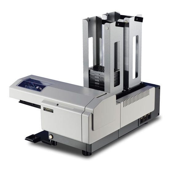
- Page 1 StakMax Microplate Handling System ® User Guide 5016072 A October 2011...
- Page 2 Molecular Devices equipment, software, reagents, and consumables. This document is copyright protected and any reproduction of this document, in whole or any part, is strictly prohibited, except as Molecular Devices may authorize in writing. Software that may be described in this document is furnished under a license agreement.
-
Page 3: Table Of Contents
Required Equipment ......58 To align the StakMax gripper ....59 Aligning the Microplate Transfer Position on a SpectraMax Paradigm Instrument . - Page 4 Reset ........104 StakMax Settings ......104 Alignment .
- Page 5 StakMax Microplate Handling System User Guide Chapter 5 Maintenance ......127 System Maintenance ......127 Weekly Maintenance.
- Page 6 Contents 5016072 A...
-
Page 7: Safety
Labeling on page 7 • Interrupt on page 9 Safety Guidelines Read and understand all of the safety guidelines before using the StakMax instrument. Labeling The following warning labels are attached to the StakMax instrument. Do not remove these labels. 5016072 A... - Page 8 Nameplate Instrument nameplate StakMax identification, voltage, and serial number (back of instrument) +24V 1311 Orleans Drive, Sunnyvale CA 94089 408 747-1700 StakMax input and output stack labels INPUT OUTPUT STACK STACK Laser-based barcode reader safety label (internal) Wavelength: 630-680 nm, Maximum...
-
Page 9: Interrupt
Paradigm® Multi-Mode Detection Platform for danger to fingers Interrupt The StakMax microplate handler has an Interrupt button located on the left side of the front panel (as shown below). Pressing the button interrupts the operation of the StakMax microplate handler, immediately stops any StakMax microplate handler movement, and then resets the entire system. - Page 10 Safety 5016072 A...
-
Page 11: Chapter 1 Introduction
2000/4000 Microplate Washer ® User Guide for operational details. The StakMax instrument is a microplate handler that can be attached to several different types of microplate instruments. This manual includes the information and procedures required to integrate each of the... -
Page 12: About This Manual
Introduction About this Manual The StakMax Microplate Handling System User Guide provides instructions for the proper setup, installation and use of the StakMax microplate handler and software. Before you use the instrument for the first time, we recommend that you read the entire manual to familiarize yourself with the basic operating procedures. -
Page 13: Chapter 2 Installation And Set Up
StakMax microplate handler involves installing the StakMax USB driver and aligning the microplate handler drawer with the StakMax microplate gripper. Note: The StakMax USB driver enables the StakMax Software, which is installed with the SoftMax Pro Software version 6.1 (or later). -
Page 14: Installing The Stakmax Microplate Handling System
WARNING! Do not operate the instrument in a cold room with a temperature below 10°C. Before installing the StakMax microplate handler, make sure the foam blocks have been removed from the input stack and the arm. To install the StakMax microplate handler 1. -
Page 15: Unpacking The System
Unpacking the System The StakMax microplate handler is packed in a specially-designed carton. It consists of an inner box, which contains the StakMax microplate handler and all of the included parts, and an outer box for protection. The inner box is suspended under compression between a pair of trampoline-like lids (top and bottom) to protect the StakMax system from damage. - Page 16 Installation and Set Up Figure 2-1 Removing the foam from the input stack. 8. Gently pull the foam block down and to the left and remove it from the stacker arm. See Figure 2-2. Figure 2-2 Removing the foam from the stacker arm. 5016072 A...
-
Page 17: Components
Note: The baseplate connection procedures are different for the SpectraMax Paradigm, SpectraMax L and AquaMax instruments. If you are setting up your StakMax microplate handler with a SpectraMax Paradigm, SpectraMax L or AquaMax instrument, skip now to one of the following alternate baseplate connection sections. - Page 18 To connect the baseplate 1. Place the StakMax microplate handler and the microplate reader on a hard, level surface (for example, a lab bench). 2. Place the baseplate on the left side of the StakMax microplate handler. See Figure 2-4 for the correct position.
- Page 19 3. Slide the baseplate under the protruding angle bracket that is attached to the instrument. 4. Align the baseplate with the mounting holes in the StakMax angle bracket and loosely thread the included Phillips-head screws and washers through the top baseplate and into the threads on the StakMax angle bracket.
- Page 20 Installation and Set Up 5. Lift the right side of the reader and place the feet into the two mounting cups located on the baseplate. Make sure that the reader feet are completely seated in the mounting cups. See Figure 2-6.
-
Page 21: Connecting The Spectramax L Baseplate
To connect the baseplate 1. Place the StakMax microplate handler and the SpectraMax L plate reader on a hard, level surface (for example, a lab bench). 2. Place the baseplate on the left side of the StakMax microplate handler. 5016072 A... - Page 22 Installation and Set Up 3. Align the mounting holes of the SpectraMax L baseplate with the two mounting holes in the back of the StakMax “L” bracket. See Figure 2-8. Figure 2-8 Aligning the SpectraMax L baseplate to the ®...
- Page 23 StakMax Microplate Handling System User Guide 5. Lift the right side of the reader and place the feet into the two mounting cups located on the baseplate. Make sure that the plate reader feet are completely seated in the mounting cups.
-
Page 24: Connecting The Aquamax Baseplate
1. Place the microplate handler on a hard, level surface. Make sure that the power supply and round serial port are accessible. 2. Align the AquaMax baseplate with the L brackets on the StakMax microplate handler. Make sure that This side up is visible on the baseplate. - Page 25 StakMax Microplate Handling System User Guide on the StakMax microplate handler. Loosely attach until both screws are connected, then tighten the screws. See Figure 2-12. Figure 2-12 Using captive screws to attach the baseplate. 4. Place the washer positioning pins, on the bottom of the washer, into the corresponding holes in the baseplate.
- Page 26 Installation and Set Up 5. Confirm that the StakMax microplate handler is set up correctly. Figure 2-14. Figure 2-14 Confirming correct physical set-up. 6. Connect the StakMax cables. See Connecting the StakMax Cables on page Note: Additional connection and usage information can be found in the AquaMax 2000/4000 Microplate Washer User Guide.
-
Page 27: Connecting The Spectramax Paradigm Baseplate
StakMax Microplate Handling System User Guide Connecting the SpectraMax Paradigm Baseplate You must connect the StakMax microplate handler to the SpectraMax Paradigm microplate reader with the provided baseplate and mounting hardware. To connect the SpectraMax Paradigm baseplate 1. Place the StakMax microplate handler and the microplate reader on a hard, level surface (for example, a lab bench). - Page 28 Installation and Set Up 5. Use the 2.5 mm hex key screwdriver to remove one of the rear feet from the reader. See Figure 2-15. Figure 2-15 Removing a rear foot from the reader 5016072 A...
- Page 29 StakMax Microplate Handling System User Guide 6. Re-use the foot and the washer and insert a black spacer bushing between the foot and the reader, and then use a new screw from the accessory kit to reattach the foot to the base of the reader.
- Page 30 Figure 2-17 Attaching baseplate to the reader 11. Return the plate reader to an upright position and then install the StakMax microplate handler stand. See Installing the StakMax Microplate Handler Stand on page 5016072 A...
- Page 31 To perform a front installation on page To perform a side-by-side installation 1. Position the StakMax microplate handler stand to the right of the microplate reader and slide the slots on the instrument stand onto the screws at the edge of the baseplate. See Figure 2-18.
- Page 32 Installation and Set Up 2. Use the 2.5 mm hex key screwdriver to tighten the screws, as shown in Figure 2-19. Figure 2-19 Attaching the StakMax microplate handler stand to the reader Item Description Front Screw Rear Screw 5016072 A...
- Page 33 StakMax Microplate Handling System User Guide Figure 2-20 Completed side-by-side installation 5016072 A...
- Page 34 Installation and Set Up To perform a front installation Note: To open the bottom cartridge drawer after performing a front installation, you need to remove the front cover from the cartridge drawer. The cover is held in place with magnets. See To open the cartridge drawer on page 102.
- Page 35 2.5 mm hex key screwdriver to attach the front installation adapter in its place, as shown in Figure 2-22 Figure 2-23. Figure 2-22 Attaching the front installation adapter Figure 2-23 StakMax instrument stand with front installation adapter attached 5016072 A...
- Page 36 Installation and Set Up 3. Align the threaded holes on the front installation adapter with the screws on the front of the baseplate. See Figure 2-24. Figure 2-24 Threaded adapter holes aligned with baseplate screws 4. Use the 2.5 mm hex key screwdriver to tighten the screws. See Figure 2-25.
- Page 37 StakMax Microplate Handling System User Guide Figure 2-26 Completed front installation Installing the Plate Drawer Protection Stand Depending on whether you are performing a side-by-side installation or a front installation, use the clamp on the appropriate side of the baseplate to secure the plate drawer protection stand to the plate reader.
- Page 38 Installation and Set Up To install the plate drawer protection stand 1. Slide the lock bracket out from the baseplate until it stops. See Figure 2-27. Figure 2-27 Baseplate with lock bracket slid out 2. Place the alignment studs (on the bottom of the plate drawer protection stand) in the holes on the baseplate.
- Page 39 See Figure 2-29. Figure 2-29 Lock bracket in baseplate Note: The cartridge drawers cannot open when the StakMax microplate handler is in place. To open a cartridge drawer, see To open the cartridge drawer on page 102.
- Page 40 Note: The photographs used for this procedure are for a side-by-side installation. To install the StakMax microplate handler 1. Use the 3.0 mm hex key screwdriver to attach the alignment studs to the outermost holes on the StakMax mounting bracket. Figure 2-30. Figure 2-30 Attaching the alignment studs...
- Page 41 StakMax Microplate Handling System User Guide 2. Place the StakMax microplate handler above the instrument stand, and then slide the alignment studs on the StakMax microplate handler firmly into the alignment slots on the inner edge of the instrument stand. See Figure 2-31.
- Page 42 Installation and Set Up Setting the Plate Drawer Protection Stand Height Before using the StakMax microplate handler, set the height of the plate drawer protection stand to a safe distance between the top of the plate drawer protection stand and the bottom of the plate drawer.
- Page 43 StakMax Microplate Handling System User Guide 5. Turn the adjustment wheel until the Gap Distance Check Tool comes into light contact with the top of the protection plate and the bottom of the plate drawer. See Figure 2-33. To move the top of the plate drawer protection stand up, ...
-
Page 44: Connecting The Stakmax Cables
Installation and Set Up Connecting the StakMax Cables The StakMax microplate handler must be connected to power with the power cable, and to the computer with a USB cable. To connect the cables 1. Connect the instrument to the power supply by plugging the 1/4-inch metal connector into the DC input on the right side of the StakMax instrument. - Page 45 StakMax Microplate Handling System User Guide 2. Connect the power supply and the power cable by inserting one end of the cord into the power supply. See Figure 2-35. Figure 2-35 Connecting the power supply to the cable. 3. Connect the power cable to the wall outlet, surge suppressor or UPS, and then wait three seconds.
- Page 46 Installation and Set Up Figure 2-36 Pressing the Power/Reset button. 5. Insert one end of the USB cable into the StakMax instrument and the other end to the computer. See Figure 2-37. Figure 2-37 Connecting the USB cable. Note: If you are connecting through a USB hub, use a powered USB hub.
-
Page 47: Installing Or Replacing A Barcode Reader
3 mm allen wrench for opening side panel if necessary (included) To install a barcode reader 1. Turn off the power to the StakMax microplate handler and the reader. 2. To remove the front cover, pull the cover down. See Figure 2-38. - Page 48 Installation and Set Up 3. To remove the left side panel (when looking at the front of the StakMax microplate handler), remove the Allen screws and pull the cover down. See Figure 2-39. Figure 2-39 Removing the left side panel.
-
Page 49: Installing The Stakmax Driver
StakMax Microplate Handling System User Guide Installing the StakMax Driver If this is the first time connecting your StakMax microplate handler, the StakMax USB driver must be installed. The StakMax USB driver enables the StakMax Software, which installs with the SoftMax Pro Software ®... - Page 50 Installation and Set Up 4. In the next Found New Hardware Wizard screen, click Install the software automatically (Recommended). See Figure 2-42. Figure 2-42 Install the software automatically. 5. Click Next. The driver installs. 5016072 A...
-
Page 51: Manual Windows Xp Stakmax Driver Installation
Finish to complete the driver installation. See Figure 2-48. Figure 2-43 Driver installation complete. 7. If this is the first time connecting your StakMax, you must now align the StakMax gripper. See Aligning the StakMax Gripper on page... - Page 52 Installation and Set Up 2. In the Welcome to the Found New Hardware Wizard screen that appears, click No, not this time. See Figure 2-41. Figure 2-44 Can windows connect to Windows Update. 3. Click Next. 5016072 A...
- Page 53 StakMax Microplate Handling System User Guide 4. In the Found New Hardware Wizard window that appears, click Install from a list or specific location (Advanced). See Figure 2-45. Figure 2-45 Install from a list or specific location. 5. Click Next. The search and installation options window appears.
- Page 54 Installation and Set Up 6. Select Include this location in the search, click Browse and navigate to the C:\Program Files\Molecular Devices\SoftMaxPro 6.1 folder. Figure 2-46 Figure 2-47. Figure 2-46 Include this location search. 5016072 A...
- Page 55 StakMax Microplate Handling System User Guide Figure 2-47 Browsing for the SoftMax Pro v6.1 folder. 7. Click OK. 8. Click Next. The driver installs. 5016072 A...
- Page 56 Finish to complete the driver installation. See Figure 2-48. Figure 2-48 Driver installation complete. 10. If this is the first time connecting your StakMax, you must now align the StakMax gripper. See Aligning the StakMax Gripper on page 5016072 A...
-
Page 57: Automatic Windows 7 Stakmax Driver Installation
1. Go to Device Manager > Ports (COM & LPT) > Stacker (COM#). Figure 2-49 Locating the StakMax USB driver. 2. If this is the first time connecting your StakMax, you must now align the StakMax gripper. See Aligning the StakMax Gripper on... -
Page 58: Aligning The Stakmax Gripper
Installation and Set Up Aligning the StakMax Gripper Note: If StakMax Software is connected to a SpectraMax Paradigm instrument, skip this alignment process. The SpectraMax Paradigm instrument uses a unique alignment procedure. See Aligning the Microplate Transfer Position on a SpectraMax Paradigm Instrument on... -
Page 59: To Align The Stakmax Gripper
StakMax Microplate Handling System User Guide To align the StakMax gripper 1. Double-click the SoftMax Pro 6.1 icon located on the desktop to open the SoftMax Pro Software. Note: You must have SoftMax Pro Software version 6.1 or later to operate the StakMax microplate handler. - Page 60 Installation and Set Up 5. Click Alignment. 6. Follow the detailed on-screen instructions in the alignment wizard to complete the calibration. This process takes approximately 15 minutes to complete. Make sure that you have the two alignment tools (Figure 2-50) and other included parts available before you start the alignment process.
- Page 61 StakMax Microplate Handling System User Guide Figure 2-53 The StakMax microplate handler secured to reader. 8. Continue the alignment with Performing a Gripper Functional Check on page 5016072 A...
-
Page 62: Aligning The Microplate Transfer Position On A Spectramax Paradigm Instrument
SpectraMax Paradigm Instrument When using the SpectraMax Paradigm instrument, the microplate transfer position must be adjusted before you can use the StakMax microplate handler. In most cases, the alignment process needs to be performed only once, following installation. The StakMax Software includes a Transfer Position Teaching wizard that provides detailed on-screen instructions to assist in completing the alignment process. - Page 63 StakMax Microplate Handling System User Guide Figure 2-54 Removing silver thumbscrew (top) and cover (bottom). 3. In the SoftMax Pro Software, with SpectraMax Paradigm selected as the attached microplate instrument, click Operations > Info. 5016072 A...
- Page 64 Installation and Set Up The Instrument Information window appears. See Figure 2- Figure 2-55 Instrument Information window. 4. Click StakMax Alignment Wizard. 5016072 A...
- Page 65 StakMax Microplate Handling System User Guide The Transfer Position Teaching Wizard appears with Integration Layout window open. See Figure 2-56. Figure 2-56 Integration Layout window. 5. Select the type of integration layout that matches your installation: Side-by-side (for landscape plate orientation) ...
- Page 66 Installation and Set Up The Preparation window appears. See Figure 2-57. Figure 2-57 Preparation window. 7. Before you begin the adjustment, select check boxes to confirm the following: You have both teaching plates (Top Adjustment Plate and Bottom Adjustment Plate) There are no plates in the stacker magazines ...
- Page 67 StakMax Microplate Handling System User Guide The Stacker - Arm Movement window appears. See Figure 2- Figure 2-58 Stacker - Arm Movement window. 5016072 A...
- Page 68 Installation and Set Up 9. Place the Top Adjustment Plate onto the input stack of the stacker. See Figure 2-59. Figure 2-59 Top Adjustment Plate in input stack 5016072 A...
- Page 69 StakMax Microplate Handling System User Guide 10. Click Move to Transfer Position. See Figure 2-60. Figure 2-60 Move to Transfer Position button. 11. Check that the gripped plate is above the plate protection stand where the reader plate drawer opens and then click Next. See Figure 2-60.
- Page 70 Installation and Set Up The Reader-Eject Plate Drawer window appears. See Figure 2-61. Figure 2-61 Reader-Eject Plate Drawer window. 5016072 A...
- Page 71 StakMax Microplate Handling System User Guide 12. Click Eject. See Figure 2-62. Figure 2-62 Eject clicked. The plate drawer opens on the opposite side from the stacker arm to make it easier to place the Bottom Alignment Plate in the carriage.
- Page 72 Installation and Set Up 13. When the plate drawer opens, place the Bottom Adjustment Plate with Landscape orientation (for side-by-side installation) or Portrait orientation (for front installation) on the plate drawer. Figure 2-63. Figure 2-63 Bottom Adjustment Plate in reader plate drawer 14.
- Page 73 StakMax Microplate Handling System User Guide The Reader-Position Transport window appears. See Figure 2-64 Figure 2-64 Reader - Position Transport window. 15. If necessary, click the Left, Right, Backward, and Forward controls to adjust the positioning of the Bottom Adjustment...
- Page 74 Installation and Set Up Figure 2-65 Top Adjustment Plate and Bottom Adjustment Plate properly aligned 16. Click Next to continue. 5016072 A...
- Page 75 StakMax Microplate Handling System User Guide The Stacker-Transfer Test window appears. See Figure 2-66. Figure 2-66 Stacker - Transfer Test window. 17. Select the check box to load and eject the plate drawer on the opposite side from the stacker arm to make it easy to remove the plate.
- Page 76 Installation and Set Up 21. Select the check box to move the plate drawer to the opposite position for easy removal of the Top Adjustment Plate, and then click Next to continue. See Figure 2-67. Figure 2-67 Move the plate drawer to a safe position check box.
- Page 77 StakMax Microplate Handling System User Guide The Adjustment Complete window appears. See Figure 2-68. Figure 2-68 Adjustment Complete window. 22. Remove the Top Adjustment Plate from the plate drawer and select the check box to indicate that you removed the Top Adjustment Plate from the reader.
-
Page 78: Performing A Gripper Functional Check
Installation and Set Up Performing a Gripper Functional Check Following gripper alignment, perform the following functional check procedure to make sure that the StakMax microplate handler is operational. Required Equipment • 5 empty microplates (located in the accessory kit) To perform a gripper functional check 1. -
Page 79: Chapter 3 Operation
Starting the StakMax Microplate Handling System Turning the StakMax Microplate Handler On and Off The power button is located on the lower-front side of the StakMax microplate handler. The Power/Reset button operates as a Power On button, Emergency Interrupt, and Reset button. -
Page 80: Opening The Stakmax Software Window
Operation To turn the StakMax microplate handler on To turn the StakMax microplate handler on, plug in the power cord and press the green button. To turn the StakMax microplate handler off To turn the StakMax microplate handler off, unplug the power cord. - Page 81 StakMax Microplate Handling System User Guide Note: Make sure you avoid any substance that can adhere plates together in the stacker. For example, build up of proteins on the plate top or adhesive from plate seals are common substances that can cause plates to adhere together.
- Page 82 Operation 2. Align the magazine over the stacked plates. See Figure 3-3. Figure 3-3 Aligning magazine over stacked plates. 3. Carefully lower the magazine over the stacked plates. See Figure 3-4. Figure 3-4 Loading the magazine from the bottom. 5016072 A...
- Page 83 StakMax Microplate Handling System User Guide 4. The magazine picks up all of the plates except the bottom plate. Figure 3-5. Figure 3-5 Magazine does not pick up last plate when loaded from the bottom. Note: Always stack one extra plate if you are loading the magazine from the bottom because the bottom plate is not picked up.
-
Page 84: Continual Feed
Note: Use the single plate loading tool if you are not using a magazine to stack the microplates. You can use the StakMax microplate handler to manually feed up to 50 plates into the input or output stack. If you choose to read plates until empty, you can continuously feed plates into the StakMax microplate handler. -
Page 85: Magazine Loading And Unloading Tool
StakMax Microplate Handling System User Guide Magazine Loading and Unloading Tool The optionalStakMax Magazine Loading and Unloading Tool assists in loading and unloading a group of microplates to and from a StakMax magazine. Use the Magazine Loading and Unloading tool if you: •... - Page 86 Operation To load plates into a StakMax magazine 1. Remove the Unload Plate Ring from the Plate Loading Base and set it aside. The Unload Plate Ring is not used for loading plates. 2. Place the stack of plates that you want to load onto the Plate Loading Base.
- Page 87 StakMax Microplate Handling System User Guide 6. Using the magazine handle, slowly lift the loaded magazine straight up and off the Plate Loading Base, and relocate the magazine and plate stack to an appropriate location. Figure 3-9 Loaded magazine removed from Plate Loading Base 7.
- Page 88 Operation To unload plates from a StakMax magazine 1. Place the Unload Plate Ring onto the Plate Loading Base and make sure it is securely seated in the base. Figure 3-10 Unload Plate Ring seated in Plate Loading Base 2. Using the magazine handle, pick up the loaded magazine.
- Page 89 StakMax Microplate Handling System User Guide 3. Carefully lower the loaded magazine over the top of the tool, aligning the corners of the black aluminium magazine base into the blue raised corners of the Unload Plate Ring. Figure 3-11 Loaded magazine positioned over tool 4.
- Page 90 Operation 5. When the magazine is securely seated on the Unload Plate Ring, the four (4) hooks at the four (4) corners on the bottom of the magazine are retracted to allow the plates to slide out from the bottom of the magazine. Figure 3-12 Loaded magazine seated on tool 5016072 A...
- Page 91 StakMax Microplate Handling System User Guide 6. Carefully lift up the empty magazine and the Unload Plate Ring until you clear the plate stack. CAUTION! When removing the empty magazine and the Unload Plate Ring, do not touch the unsupported stack of plates.
- Page 92 Operation 7. Place the empty magazine and the Unload Plate Ring in a stable location. Figure 3-14 Empty magazine and ring next to plates 5016072 A...
- Page 93 StakMax Microplate Handling System User Guide 8. Use your thumbs to unclip the Unload Plate Ring from the magazine by pushing the two spring clips on the Unload Plate Ring away from the crossing bars on the sides of the magazine.
-
Page 94: Single Plate Loading Tool
Operation Single Plate Loading Tool Place the single plate loading tool into the input area of the stacker. Load a single plate in the opening. See Figure 3-16. Figure 3-16 (A) Single plate loading tool, (B) inserting the tool, (C) loading a plate. -
Page 95: Using Stakmax Software
Using StakMax Software This section describes the main elements of the StakMax Software interface. You can use the StakMax Software to manually control basic stacker functions, for example, starting and stopping plate reads, moving plates from the reader to the input or output stacks, and moving plates within the stacker. -
Page 96: Start Read
Start Read button. CAUTION! To prevent data loss, make sure that Auto Save is enabled for each protocol you want to run before you start the StakMax software to run automated reads. Refer to the SoftMax Pro User Guide ®... - Page 97 StakMax Microplate Handling System User Guide After you click Start Read, the Read Plate window appears. See Figure 3-19. Figure 3-19 The Read Plate window. The Read Plate window is divided into the following sections: Number of Plates: Type a specific number of plates or select All of Input Stack.
- Page 98 Operation Action when plate section(s) filled: Select an action to take if there are more plates to read than sections in the assigned protocol. The software will either open new copies of the protocol or will append plate sections to the original protocol until all of the plates have been read. •...
- Page 99 Destination: This field should display “The results will be saved using Autosave” because AutoSave is required to start a plate read from the Read Plate window. Read: Click to start the reading. Cancel: Click to cancel the action and return to the main StakMax window. 5016072 A...
- Page 100 9. Click Read. After the reading starts, the status is displayed in the main StakMax window next to Status. You can also click the Status Window button to view more details about the reading. Note: If you leave a plate in the reader and try to run a new plate, the system detects that a plate is present and moves the new plate back to the input stack.
-
Page 101: Stop Read
Emergency Stop The Emergency Stop button immediately shuts down the entire system, including the StakMax Microplate Handling System and the reader. After you click the Emergency Stop button, clear any object that is in the way, remove any plates that are in the drawer, and then click the Reset button in the main StakMax window. -
Page 102: Return Plate
Operation Return Plate The Return Plate button manually moves one plate from the reader to the output stack. You can use this command to clear a plate that was left in the reader or to help determine if a component is out of sync. Restack The Restack button moves plates from the output stack to the input stack. -
Page 103: Demo
StakMax Microplate Handling System User Guide Demo The Demo button continuously moves plates to the instrument from the stacker and back, switching the plate source between the input and output stacks as they fill and empty. Demo mode is primarily used to demonstrate the plate movement and is generally not used under normal operation. -
Page 104: Reset
Therefore, the Power/Reset button should be used only in rare cases when the stacker does not reset itself. Note: In case of emergency, you can press the Power/Reset button on the front of the StakMax microplate handler to reset the entire system. StakMax Settings The Settings button is located on the bottom-left corner of the main StakMax Software interface. - Page 105 StakMax Microplate Handling System User Guide Figure 3-24 The StakMax Settings window. Barcoding Select the Use Barcode check box (see Figure 3-24) in the StakMax Settings window to enable barcode reading. Select Rename to overwrite the Plate section name with the barcode or select Append to add the barcode to the Plate section name.
-
Page 106: Alignment
Perform alignment immediately after you connect a microplate instrument to the StakMax system. See Aligning the StakMax Gripper on page 58 Aligning the Microplate Transfer Position on a SpectraMax Paradigm Instrument on page Note: The gripper alignment process takes approximately 15 minutes to complete. -
Page 107: Status Window
StakMax Microplate Handling System User Guide Status Window The Status window displays details about the current run, including low level commands and error messages. For a list and description of error messages, see Table 8-1 on page 139. To print the contents of the Status window, select the Print button located on the bottom-left side of the window. - Page 108 Operation 5016072 A...
-
Page 109: Chapter 4 Scripting
Scripting Scripting is an optional tool that can be used to automate a series of commands that control runs. There are two ways to create a script. You can edit and use one of the default scripts as a template or you can start with a blank document and create a new script. - Page 110 Scripting To open the script editor Click the Scripting button that is located in the middle section of the StakMax software interface. See Figure 4-1. Figure 4-1 The Scripting window. 5016072 A...
- Page 111 (middle), and the Check Syntax, Print, Remove, and Save functions (bottom middle). See Figure 4-2. The commands are grouped into four different categories starting with the most basic StakMax commands. See the following section for a definition of each command. Figure 4-2 A new script editor document. 5016072 A...
-
Page 112: Command Definitions
CAUTION! Auto Save, automatic file saving after every read operation, must be enabled prior to calling protocols through StakMax. Open Document: opens an existing SoftMax Pro document. You must specify the correct path for the document. -
Page 113: Advanced Commands
StakMax Microplate Handling System User Guide Start Read: starts an instrument reading. Stop Read: stops an instrument reading. Select Section: selects a section by name. Select Section Num: selects a section by number. Name Current Section: names the section that is currently selected. -
Page 114: Misc Commands
To create a new script from a template 1. Click the Scripting button on the StakMax software interface to open the main Scripting window. See Figure 4-4. - Page 115 StakMax Microplate Handling System User Guide Figure 4-4 The Scripting window. 2. Click Open. 3. Select one of the default scripts to use as a template and click Open. The example described below uses the Read_One_Plate script. See Figure 4-5.
-
Page 116: Adding Commands
Scripting The command script displays in the middle section of the screen. Figure 4-6. Figure 4-6 The Script editor screen. Adding Commands To add a command to a script 1. Select the command above where you want to insert the new command. - Page 117 StakMax Microplate Handling System User Guide The command name appears in the Command Edit field. See Figure 4-7. 2. Select the command. 3. The command name appears in the Command Edit 4. Click field. 1. New command is inserted below selected command.
- Page 118 Scripting The new command is inserted after the selected command. In the example script, notice that the Record Barcode command was inserted after the Select Next Plate Section command. Figure 4-8. Figure 4-8 Command script after a new command is inserted. 4.
-
Page 119: Removing Commands
StakMax Microplate Handling System User Guide Removing Commands To remove a command 1. Select the command name in the Command Script section of the screen. See Figure 4-9. Figure 4-9 Selecting a command to remove. 2. Click Remove. Note: Click the Remove All button only if you want to remove the entire command script. - Page 120 Scripting 3. If you have the Allow Edit Prompting feature turned on, click OK to verify that you want to remove the command. Click Cancel to interrupt and stop the remove command process. Figure 4-10 The Edit prompting dialog box. Figure 4-11, the Record Barcode command was removed from the script.
-
Page 121: Changing The Order Of Commands
StakMax Microplate Handling System User Guide 5. If you do not want to make any further changes to the command script, go to Saving Scripts on page 125. If you want to change the order of the commands, go to Changing the Order of Commands on page 121. - Page 122 Scripting 2. Verify that the command was moved to the new position in the script. See Figure 4-13. Figure 4-13 Command script after a command is moved. 3. Repeat Step 1 Step 2, as necessary. 4. When you have finished making changes, go to Saving Scripts on page 125.
-
Page 123: Checking The Syntax
StakMax Microplate Handling System User Guide Checking the Syntax The Check Syntax button runs a script and looks for invalid commands. An invalid command is defined as having an unknown or missing required parameter. If a command is created using the Add button, it is guaranteed to be valid. -
Page 124: Using Repeats
Scripting Using Repeats Use the Begin/End Repeat commands to repeatedly execute a set of commands. Specify the number of required repetitions when you add the Begin Repeat command. The block of commands between the Begin Repeat command and the End Repeat command runs the specified number of times. -
Page 125: Saving Scripts
2. In the File name field, type a unique file name. Figure 4-16. Note: The StakMax Software defaults to the StakMax Scripts folder to save new scripts. To change the destination folder, click on the downward facing arrow next to the Save In field. -
Page 126: Printing Scripts
Scripting Printing Scripts To print a script 1. At the bottom of the script window, click Print. 2. Select the appropriate printer from the list. 3. Click OK. 5016072 A... -
Page 127: Chapter 5 Maintenance
The following maintenance procedures apply only to the SpectraMax Paradigm instrument. Removing the StakMax instrument from the instrument stand You might need to move the StakMax instrument to access the cartridge drawers. To remove the StakMax Instrument from the instrument stand 1. Turn off the power. - Page 128 Molecular Devices service representatives initially install the lower baseplate and stand that connects the StakMax instrument to the SpectraMax Paradigm Platform. However, you might occasionally need to remove and attach the StakMax instrument in order to gain access to the cartridge drawers. To open the cartridge drawer 1.
-
Page 129: Technical Support
SpectraMax Paradigm Platform. In most cases, the alignment process needs to be performed only once, following installation. Occasionally, users might need to use the StakMax Software Transfer Position Teaching wizard to re-align the position. The Transfer Position Teaching wizard provides detailed on-screen instructions to assist in completing the alignment process. - Page 130 Maintenance WARNING! SHOCK HAZARD: Removal of protective covers that are marked with the High Voltage warning symbol can result in a safety hazard. WARNING! Always disconnect the power cord from the main power source before performing any maintenance procedure that requires removal of any panel or cover or disassembly of any interior instrument component.
-
Page 131: Chapter 6 Troubleshooting
Can't move axis if it's Press the occurred during a already in motion. Power/Reset button. motion. Error: A Problem Generic EPROM error. Call Molecular Devices occurred with the Technical Support +1- EPROM. 800-635-5577. Error: A problem Carriage drop off Re-align the... - Page 132 Check for object occurred during a after opening. blocking movement motion. and then re-align. Error: A Problem EPROM space is larger Call Molecular Devices occurred with the than portion of FLASH Technical Support +1- EPROM. memory allocated. 800-635-5577. Error: A problem...
-
Page 133: Appendix A System Diagrams And Specifications
50-plate stack = 40.40 inches (1026.2 mm) • Power source: 100–240 VAC, autoranging line voltage, 50/60 Hz, ~1.5A • Operating temp.: 10°C–40°C • Connectivity: USB 2.0 (requires SoftMax Pro Software version ® 6.1 or later and StakMax Software version 5.4.4 or later) 5016072 A... -
Page 134: Diagrams
[ ] = metric 20 plate stack = 21.27 inches (540.3 mm) No [ ] = imperial 40 plate stack = 31.20 inches (792.5 mm) 50 plate stack = 40.40 inches(1026.2 mm) Figure A-1 Dimensions of the StakMax instrument 5016072 A... - Page 135 StakMax Microplate Handling System User Guide 526.82 20.7 865.51 34.1 231.14 Vertical clearance: [ ] = metric 20 plate stack = 21.27 inches (540.3 mm) No [ ] = imperial 40 plate stack = 31.20 inches (792.5 mm) 50 plate stack = 40.40 inches (1026.2 mm)
- Page 136 System Diagrams and Specifications Figure A-3 Dimensions of the StakMax microplate handler and SpectraMax Paradigm System (side-by-side orientation) 5016072 A...
- Page 137 StakMax Microplate Handling System User Guide Figure A-4 Dimensions of the StakMax microplate handler and SpectraMax Paradigm System (front orientation) 5016072 A...
- Page 138 System Diagrams and Specifications Figure A-5 The SpectraMax L reader dimensions ® 5016072 A...
- Page 139 StakMax Microplate Handling System User Guide Figure A-6 The AquaMax microplate washer dimensions ® 5016072 A...
- Page 140 System Diagrams and Specifications 5016072 A...
Need help?
Do you have a question about the StakMax and is the answer not in the manual?
Questions and answers