Festo CPX-FB14 Description
Terminal cpx, bus node, canopen networkprotocol
Hide thumbs
Also See for CPX-FB14:
- Electronic manual (155 pages) ,
- Brief description (74 pages) ,
- Electronic manual (154 pages)

Related Manuals for Festo CPX-FB14


Summary of Contents for Festo CPX-FB14
- Page 1 Terminal CPX Bus node CPX-FB14 Description CANopen network protocol 526410 en 1411d [8041138]...
- Page 3 ........526410 © (Festo AG & Co. KG, Postfach, 73726 Esslingen, Germany, 2013) Internet: http://www.festo.com E-Mail: service_international@festo.com...
- Page 4 Contents and general instructions ® ® ® CANopen , TORX , CiA are registered trademarks of the respective trademark owners in certain countries. Festo P.BE-FB14-EN en 1411d English...
-
Page 5: Table Of Contents
........1-27 1.3.5 Connecting with the fieldbus plug from Festo ....1-28 1.3.6... - Page 6 ........3-12 Diagnostics via the I/O diagnostic interface ......3-13 Festo P.BE-FB14-EN en 1411d English...
- Page 7 ..........Technical data, bus node CPX-FB14 .
-
Page 8: Intended Use
Contents and general instructions Intended use The bus node CPX-FB14 described in this description has been designed exclusively for use as a participant on the CANopen fieldbus. The CPX terminal must only be used as follows: – As intended in industrial environments;... -
Page 9: Target Group
This description is intended exclusively for technicians trained in control and automation technology who have experience in installing, commissioning, programming and diagnosing participants on the CANopen fieldbus. Service Please consult your local Festo repair service if you have any technical problems. Festo P.BE-FB14-EN en 1411d English... -
Page 10: Instructions Regarding This Description
EDS file from 23 Apr. 13 Software status (SW) or revision no. (Rev) è type plate Tab. 0/1: Revisions of the CPX-FB14 until June 2013 An overview of the structure of the CPX terminal user docu mentation is contained in the CPX system description. -
Page 11: Important User Information
... means that failure to observe this instruction may result in material damage. In addition, the following pictogram marks passages in the text which describe activities with electrostatically sensitive devices: Electrostatically sensitive devices: Incorrect handling may cause damage to devices. Festo P.BE-FB14-EN en 1411d English... - Page 12 Recommendations, tips and references to other information sources. Accessories: Specifications on necessary or useful accessories for the Festo product. Environment: Information on the environmentally friendly use of Festo products. Text designations Bullets denote activities that may be carried out in any • desired order.
- Page 13 The I/O diagnostic interface is a bus-independent diagnostic interface at I/O level that permits access to internal data of the CPX terminal I/O modules Collective term for the CPX modules which provide digital inputs and outputs Festo P.BE-FB14-EN en 1411d English...
- Page 14 Interface between CPX modules and pneumatics modules Short circuit/overload SCS, SCO, SCV Short circuit/overload sensor supply, outputs, valves Status bits Internal inputs which supply coded common diagnostic messages è Function module Technology module Tab. 0/2: Product-specific terms and abbreviations Festo P.BE-FB14-EN en 1411d English...
-
Page 15: Installation
Installation Chapter 1 Installation Festo P.BE-FB14-EN en 1411d English... - Page 16 ........1-27 1.3.5 Connecting with the fieldbus plug from Festo ....1-28 1.3.6...
-
Page 17: General Instructions On Installation
The CPX bus node contains electrostatically sensitive devices. Do not touch any electrical or electronic components. • Observe the handling specifications for electrostatically • sensitive devices. They will help you avoid damage to the electronics. Festo P.BE-FB14-EN en 1411d English... - Page 18 1. Installation Information about mounting of the CPX terminal can be found in the CPX system description (P.BE-CPX-SYS-...). Festo P.BE-FB14-EN en 1411d English...
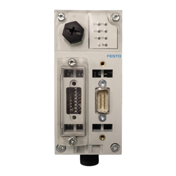
- Page 19 Fieldbus connection (9-pin sub-D plug) Transparent cover for the DIL switches Fig. 1/1: Connection and display components on the CPX bus node Note Use protective caps to seal unused connections. This is how you achieve protection class IP65/IP67. Festo P.BE-FB14-EN en 1411d English...
- Page 20 Always use the correct screws for the interlocking block, which depend on whether the block is made of metal or plastic: – for plastic interlinking blocks: self-tapping screws – for metal interlinking blocks: screws with metric thread. Festo P.BE-FB14-EN en 1411d English...
- Page 21 4. Only tighten the screws by hand. Place the screws so that the self-cutting threads can be used. 5. Tighten the screws with a TORX screwdriver size T10 with 0.9 ... 1.1 Nm torque. Festo P.BE-FB14-EN en 1411d English...
-
Page 22: Settings Of The Dil Switches On The Bus Node
Disconnect the power supply before removing the cover. • Make sure that the seal is seated correctly when attach • ing the cover! Tighten the two mounting screws with a max. torque of • 0.4 Nm. Festo P.BE-FB14-EN en 1411d English... -
Page 23: Settingthe Dil Switches
7. For remote I/O operating mode: Set the CPX diagnostic mode (DIL switch 5). For remote controller operating mode: Set the required number of logical I/Os of the CPX-FB14 (DIL switch 5). 8. Mount the cover (section 1.2.1). Festo P.BE-FB14-EN en 1411d English... - Page 24 DIL switch 4: baud rate DIL switch 5: CPX diagnostics mode or number of log. I/Os with “remote controller” Fig. 1/3: DIL switch in the bus node (additional information on … in the following) 1-10 Festo P.BE-FB14-EN en 1411d English...
- Page 25 An FEC or CEC integrated into the CPX terminal takes over DIL 1.2: OFF I/O control. This operating mode is only useful if an FEC or CEC is integrated into the CPX terminal. Tab. 1/1: DIL switch 1: (operating mode) 1-11 Festo P.BE-FB14-EN en 1411d English...
- Page 26 The setting of the DIL switch has precedence especially over the parameterisation of defined settings. No emergency mes sage is transmitted with error filtering. 1-12 Festo P.BE-FB14-EN en 1411d English...
- Page 27 CANopen Station number 1; ...; 127 Tab. 1/3: Permissible station numbers Recommendation: Assign the station numbers in ascending order. Assign the station numbers in accordance with the machine structure of your system. 1-13 Festo P.BE-FB14-EN en 1411d English...
- Page 28 38 2 + 4 + 32 = 1 + 4 = Tab. 1/4: Examples of set station numbers (binary coded) On the following pages you will find an overview of the station number settings. 1-14 Festo P.BE-FB14-EN en 1411d English...
- Page 29 1. Installation Station Station Activation of LSS (from software version V1.26) Tab. 1/5: Setting of the station numbers 1 … 31: position of the DIL switch 1-15 Festo P.BE-FB14-EN en 1411d English...
- Page 30 1. Installation Station Station Tab. 1/6: Setting of the station numbers 32 … 63: position of the DIL switch 1-16 Festo P.BE-FB14-EN en 1411d English...
- Page 31 1. Installation Station Station Tab. 1/7: Setting of the station numbers 64 … 95: position of the DIL switch 1-17 Festo P.BE-FB14-EN en 1411d English...
- Page 32 1. Installation Station Station Tab. 1/8: Setting of the station numbers 96 … 127: position of the DIL switch 1-18 Festo P.BE-FB14-EN en 1411d English...
- Page 33 1. Installation Activation of the layer setting service (LSS) with DIL switch The bus node CPX-FB14 supports layer setting service (LSS) in accordance with CiA DSP-305. With the help of the layer setting service (LSS), the LSS mas ter can change the baud rate and node number of an LSS slave via the CANopen bus.
- Page 34 250 kB 4.1: ON 4.2: OFF 500 kB 4.1: OFF 4.2: ON 1000 kB 4.1: ON 4.2: ON Tab. 1/9: DIL switch 4 (baud rate) The following table shows the settings of the DIL switch. 1-20 Festo P.BE-FB14-EN en 1411d English...
- Page 35 The diagnostics mode (status bits or I/O diagnostics interface) occupies 2 bytes or 4 bytes of address space (16 I-bits or 16 I/O-bits; 8 I-bits remain unused in the status bits mode) Tab. 1/10: DIL switch 5 (diagnostics mode or number of I/O bytes with remote controller) 1-21 Festo P.BE-FB14-EN en 1411d English...
- Page 36 (2) Subsequent activation of the diagnostics mode requires reconfiguration The CPX-internal I/O image can be displaced during subsequent activation of the diagnostics mode (status bits or I/O diagnostics interface). Restart the CPX terminal with Power OFF/ON. 1-22 Festo P.BE-FB14-EN en 1411d English...
-
Page 37: Connecting The Fieldbus
Use a twisted, screened 4-wire cable as fieldbus line. The CANopen bus interface of the CPX terminal is supplied with power via the fieldbus line. If the Festo fieldbus plug is used, a cable diameter of 5...8 mm or 7...10 mm is permissible. Note... -
Page 38: Fieldbus Baud Rate And Fieldbus Length
T-adapter and maximum branch line length are permitted for your controller. Also take into account the sum of the branch line lengths • when calculating the maximum permitted length of the fieldbus cable. 1-24 Festo P.BE-FB14-EN en 1411d English... -
Page 39: Information On Connecting The Fieldbus
The following tolerance in the bus interface power supply (pin 3/pin 9 on the sub-D plug) applies to the CPX terminal: = 30.0 V = 11.0 V Recommendation: Place the power supply unit approximately at the centre of the bus. 1-25 Festo P.BE-FB14-EN en 1411d English... - Page 40 1. Installation With the Festo fieldbus plug, you can implement a T-adapter (è Fig. 1/6). Ó Ó Ó Ó Fieldbus Branch line Voltage supply T-adapter (T-tap) Screening Fieldbus plug with T-adapter function Fig. 1/6: Structure of the bus interface and example of connection 1-26 Festo P.BE-FB14-EN en 1411d English...
-
Page 41: Fieldbus Interface
There is 9-pin sub-D plug on the bus node for connecting the CPX terminal to the fieldbus. This connection is used for the incoming and continuing fieldbus line. You can connect the CPX terminal with the fieldbus plug from Festo type FBS-SUB-9-BU-2x5POL-B. Note Note that only the Festo fieldbus plug guarantees compli... -
Page 42: Connecting With The Fieldbus Plug From Festo
(T-TAP function). Note The clamp strap in the Festo fieldbus plug is connected only capacitively internally with the metal housing of the sub-D socket. This prevents equalizing currents from flow... - Page 43 Bus IN Clamp strap for Bus OUT screened connection Protective cap if connection is not used Fieldbus continuing (OUT) Fieldbus incoming (IN) Only capacitively connected Fig. 1/7: Fieldbus plug from Festo, type FBS-SUB-9-BU-2x5POL-B 1-29 Festo P.BE-FB14-EN en 1411d English...
-
Page 44: Further Connection Possibilities For The Fieldbus With Adapters
Connect the screening. • There are further connection options for the CPX terminal with adapters which can be ordered separately from Festo: – M12 adapter 5-pin (protection class IP 65) type FBA-2-M12-5POL –... - Page 45 Note Use protective caps to seal unused connections. • You will then achieve protection class IP65. Order this connection from Festo (FBA-2-M12-5POL). M12 adapter Pin no. 1. Screening 2. 24 V DC bus (max. 4 A) 3.
- Page 46 5. 24 V DC bus (max. 4 A) 2x5-pin terminal strip Fig. 1/9: Pin assignment of the fieldbus interface (5-pin screw terminal adapter) If you connect the fieldbus via the terminal strip FBSD-KL-2x5POL from Festo, you can implement a T-adapter function. 1-32 Festo P.BE-FB14-EN en 1411d English...
-
Page 47: Bus Terminal With Terminating Resistors
If you are using T-adapters, install the terminating resistor at the unused output of the T-adapter. Recommendation: Mount a terminating resistor for the bus terminal in the Festo fieldbus plug (120 Ω, 0,25 W, è Fig. 1/10). Protective cap Resistor for bus termination (120 Ω, 0.25 W) -
Page 48: Power Supply
The pin allocation of the CPX interlinking blocks can be found in the CPX system description and the package insert for the CPX interlinking block. 1-34 Festo P.BE-FB14-EN en 1411d English... -
Page 49: Commissioning
Commissioning Chapter 2 Commissioning Festo P.BE-FB14-EN en 1411d English... -
Page 50: Configuration
..........2-81 2.4.13 Function assignment and virtual modules ....2-85 Festo P.BE-FB14-EN en 1411d English... - Page 51 ..... . . 2-93 2.6.1 Correct commissioning, normal operating status ....2-94 Festo P.BE-FB14-EN en 1411d English...
-
Page 52: Commissioning On A Canopen Master
CANopen Tab. 2/1: CANopen specifications taken into account with the CPX terminal In order to understand this chapter, you should be familiar with CANopen and the specifications CiA 301, CIA DSP 305 and CiA 401. Festo P.BE-FB14-EN en 1411d English... -
Page 53: General Information On Canopen
Process Data Objects may be transmitted based on event control, synchronised to a system clock, or on request. The Service Data Objects (SDO) form a point-to-point connection and permit access to every entry in the object directory of a node. Festo P.BE-FB14-EN en 1411d English... -
Page 54: Configuration
The LSS commands are sent from the LSS master with COB- ID 0x7E5 (communication object identifier). The LSS slave answers with COB-ID 0x7E4. To make the bus node CPX-FB14 configurable via LSS, it must be placed in the LSS configuration mode. There are two differ ent possibilities for this: –... - Page 55 Manufacturer ID (assigned by CiA) 00 00 00 1D Product code Product code 00 00 00 CD Revision number Software version xx xx xx xx Serial number Serial number xx xx xx xx Tab. 2/3: Selective mode change Festo P.BE-FB14-EN en 1411d English...
- Page 56 Command 0x7E5 Byte Data 0x41 ProdCode 0x00 0x00 0x00 0x00 0x00 0x00 Tab. 2/5: Switch mode selective – product code The “switch mode selective – product code” command is not confirmed by the LSS slave. Festo P.BE-FB14-EN en 1411d English...
- Page 57 Switch mode selective – serial number After the fourth command is sent, the addressed LSS slave answers (vendor ID, product code, revision number and serial number must agree with the internal data of the LSS slave). Festo P.BE-FB14-EN en 1411d English...
- Page 58 COB-ID Acknowledge 0x7E4 Byte Data 0x44 Mode 0x00 0x00 0x00 0x00 0x00 0x00 Tab. 2/8: Answer to switch mode selective – serial number Mode: – 0x01 Configuration mode – 0x00 Normal mode (operation mode) 2-10 Festo P.BE-FB14-EN en 1411d English...
- Page 59 – Impermissible node ID – 0xFF Not all switch elements 1 … 7 of the DIP switch 3 are at OFF. The bus node is not in the LSS mode. Error extension: – Reserved 2-11 Festo P.BE-FB14-EN en 1411d English...
- Page 60 0x00 0x00 0x00 0x00 0x00 table entry Tab. 2/11: Configure bit timing parameters Bit timing table: – Is always 0. Table entry: – 1000 kBaud – 500 kBaud – 250 kBaud – 125 kBaud 2-12 Festo P.BE-FB14-EN en 1411d English...
- Page 61 Impermissible baud rate (baud rate is not supported) – 0xFF Not all switch elements 1 … 7 of the DIP switch 3 are at OFF. The bus node is not in the LSS mode. Error extension: – Reserved 2-13 Festo P.BE-FB14-EN en 1411d English...
- Page 62 This command can only be used in the configuration mode. COB-ID Command 0x7E5 Byte Data 0x15 Delay 0x00 0x00 0x00 0x00 0x00 0x00 Tab. 2/13: Activate bit timing Delay: – Time delay in ms The command is not confirmed by the LSS slave. 2-14 Festo P.BE-FB14-EN en 1411d English...
- Page 63 No access to the storage medium. – 0xFF Not all switch elements 1 … 7 of the DIP switch 3 are at OFF. The bus node is not in the LSS mode. Error extension: – Reserved 2-15 Festo P.BE-FB14-EN en 1411d English...
- Page 64 Tab. 2/16: Inquire vendor ID COB-ID Acknowledge 0x7E4 Byte Data 0x5A Low word Low word High word High word 0x00 0x00 0x00 Low byte High byte Low byte High byte Tab. 2/17: Answer to inquire vendor ID 2-16 Festo P.BE-FB14-EN en 1411d English...
- Page 65 Tab. 2/18: Inquire product code COB-ID Acknowledge 0x7E4 Byte Data 0x5B Low word Low word High word High word 0x00 0x00 0x00 Low byte High byte Low byte High byte Tab. 2/19: Answer to inquire product code 2-17 Festo P.BE-FB14-EN en 1411d English...
- Page 66 Tab. 2/20: Inquire revision number COB-ID Acknowledge 0x7E4 Byte Data 0x5C Low word Low word High word High word 0x00 0x00 0x00 Low byte High byte Low byte High byte Tab. 2/21: Answer to inquire revision number 2-18 Festo P.BE-FB14-EN en 1411d English...
- Page 67 Tab. 2/22: Inquire serial number COB-ID Acknowledge 0x7E4 Byte Data 0x5D Low word Low word High word High word 0x00 0x00 0x00 Low byte High byte Low byte High byte Tab. 2/23: Answer to inquire serial number 2-19 Festo P.BE-FB14-EN en 1411d English...
- Page 68 0x5E 0x00 0x00 0x00 0x00 0x00 0x00 0x00 Tab. 2/24: Inquire node ID COB-ID Acknowledge 0x7E4 Byte Data 0x5E Node ID 0x00 0x00 0x00 0x00 0x00 0x00 Tab. 2/25: Answer to inquire node ID 2-20 Festo P.BE-FB14-EN en 1411d English...
- Page 69 0x47 Low word Low word High word High word 0x00 0x00 0x00 Low byte High byte Low byte High byte Tab. 2/27: Identify product code The command is not confirmed by the LSS slave. 2-21 Festo P.BE-FB14-EN en 1411d English...
- Page 70 Low word Low word High word High word 0x00 0x00 0x00 Low byte High byte Low byte High byte Tab. 2/29: Identify revision number high The command is not confirmed by the LSS slave. 2-22 Festo P.BE-FB14-EN en 1411d English...
- Page 71 Low byte High byte Low byte High byte Tab. 2/31: Identify serial number high COB-ID Acknowledge 0x7E4 Byte Data 0x4F 0x00 0x00 0x00 0x00 0x00 0x00 0x00 Tab. 2/32: Answer to Identify serial number high 2-23 Festo P.BE-FB14-EN en 1411d English...
-
Page 72: Configuration Of The Lss Slave
1. Transfer the LSS slave into the configuration mode: Switch mode global (mode = 0x01) è Tab. 2/2 • 2. Query node number: Inquire node ID è Tab. 2/25 • 3. Configure new node number: Configure node ID è Tab. 2/9 • 2-24 Festo P.BE-FB14-EN en 1411d English... - Page 73 3. Configure new node number Configure node ID è Tab. 2/9 • 4. Configure new baud rate Configure bit timing parameters è Tab. 2/11 • 5. Save the configuration Store configuration è Tab. 2/14 • 2-25 Festo P.BE-FB14-EN en 1411d English...
-
Page 74: Addressing The Cpx Terminal
Transmit PDO 4 (standard setting). – The 16 bits of the I/O diagnostic interface must be treated like inputs and outputs. They each occupy 16 bits in the Transmit and Receive PDO 4 (standard set ting). 2-26 Festo P.BE-FB14-EN en 1411d English... - Page 75 – If the telegram received is shorter than the necessary telegram length, an error message will be output. – If the telegram received is longer, the part corresponding to the necessary length will be processed. 2-27 Festo P.BE-FB14-EN en 1411d English...
- Page 76 O8…O15 O16…O23 O24…O31 O32…O39 O40…O47 O48…O55 O56…O63 O0…O7 Transmit PDO 2 … 4 Unused Receive PDO 2 … 4 Unused Fig. 2/2: 64 logical I/Os in the PDO 1 in the remote controller operating mode 2-28 Festo P.BE-FB14-EN en 1411d English...
-
Page 77: Configuration Examples
R-PDO 4 (I/O diagnostics interface) Fig. 2/3: Assignment of the PDOs on a CPX terminal with digital I/O modules, MPA pneumatics and activated I/O diagnostic interface (standard assignment without mapping, configuration è Tab. 2/35) 2-29 Festo P.BE-FB14-EN en 1411d English... - Page 78 Tab. 2/35: Configuration for example terminal 1 from Fig. 2/3 How you can prepare a changed configuration for this ex ample with function assignment and virtual modules can be found in section 2.4.13. 2-30 Festo P.BE-FB14-EN en 1411d English...
- Page 79 Fig. 2/4: Assignment of the PDOs on a CPX terminal with digital and analogue I/O modules, VTSA pneumatics (DIL switch setting 8O) and not-activated diagnostic functions (standard assignment without mapping, configuration è Tab. 2/36) 2-31 Festo P.BE-FB14-EN en 1411d English...
- Page 80 R-PDO 1: O12 … O19 ISO plug-in (type 44) – Obj. 6200.2 DIL switch in the interface set to 1 ... 8 Obj. 6200.3 solenoid coils (8DO) Tab. 2/36: Configuration for example terminal 2 in Fig. 2/4 2-32 Festo P.BE-FB14-EN en 1411d English...
- Page 81 String 4, outputs String 1 Fig. 2/5: Assignment of the PDOs on a CPX terminal with digital I/O modules, CPX-CP interface, MPA pneumatics and non-activated diagnostic functions (standard assignment without mapping, configuration è Tab. 2/37) 2-33 Festo P.BE-FB14-EN en 1411d English...
- Page 82 CPX terminal. As a result, the remaining output bytes can be made available over other PDOs. (OW4 ... OW7 are not depicted in Fig. 2/5). Tab. 2/37: Configuration for example terminal 3 in Fig. 2/5 2-34 Festo P.BE-FB14-EN en 1411d English...
-
Page 83: Overviews
Node guarding and heart beat – Default setting of all identifiers as per CiA 301 and the station number (predefined connection set) – Variable mapping – Function assignment and virtual modules – Layer setting service (LSS) 2-35 Festo P.BE-FB14-EN en 1411d English... -
Page 84: Overview Object Directory
2.4.3 6200, 6300 Output array 2.4.4 6206/6306 Fault mode array for the outputs 6207/6307 Error state array for the outputs 64xx Analogue inputs and outputs 2.4.5 Tab. 2/38: Implemented objects of the CPX terminal 2-36 Festo P.BE-FB14-EN en 1411d English... -
Page 85: Behaviour Of The Cpx Terminal When It Is Switched On
2.3.3 Behaviour of the CPX terminal when it is switched on Power on Application initialization Communication initialization Pre-operational Stopped Operational Fig. 2/6: Status transitions of the CPX terminal (description è Tab. 2/39 on the next page) 2-37 Festo P.BE-FB14-EN en 1411d English... - Page 86 – Stored parameters (2000 … 5FFF) are not reloaded. The objects 6000 … are always loaded with the default settings after power-on Only after the transition from operational mode to stopped or pre-operational mode Tab. 2/39: Status transitions 2-38 Festo P.BE-FB14-EN en 1411d English...
-
Page 87: Default Identifier Distribution
2.3.4 Default identifier distribution The following table shows the identifier distribution: Broadcast objects Object name Object designation Range of values of the COB identifier on the CPX terminal SYNC – Tab. 2/40: Broadcast objects 2-39 Festo P.BE-FB14-EN en 1411d English... - Page 88 PDO4 (rx) 1281 … 1407 Transmit SDO SDO1 (tx) 1409 … 1535 Receive SDO SDO1 (rx) 1537 … 1663 Node guarding / Guarding heart beat 1793 … 1919 Tab. 2/41: Peer-to-Peer objects of the CPX-FB14 2-40 Festo P.BE-FB14-EN en 1411d English...
-
Page 89: Object Directories
= dependent on expansion of the CPX terminal: Bit 16: digital inputs Bit 17: digital outputs Bit 18: analogue inputs Bit 19: analogue outputs Example: CPX terminal with digital 00 03 91 01 inputs and outputs 2-41 Festo P.BE-FB14-EN en 1411d English... - Page 90 Node designation turer device name 1009 Manufac Str. – “0810” (ex Current hardware status turer hard ample) ware version 100A Manufac Str. – “V2.0” (ex Current software version turer soft ample) ware ver sion 2-42 Festo P.BE-FB14-EN en 1411d English...
- Page 91 C.-H. Time 2 00 00 00 00 C.-H. Time 6 00 00 00 00 1017 Producer – 00 00 Heart beat time [ms] heart beat COB-ID = node guard ID time Status (pre-operational, operational, stopped) 2-43 Festo P.BE-FB14-EN en 1411d English...
- Page 92 è CPX sys Module 0 Module code module 0 tem descrip Module 1 Module code module 1 tion Module 2 Module code module 2 Sequence as in CPX terminal from left to right. 2-44 Festo P.BE-FB14-EN en 1411d English...
- Page 93 COB_ID 580 + node Default COB-ID + node ID server client (tx) = unsigned Map. = Mapping possible = read only Attr. = attribute rw = read/write Tab. 2/42: Objects of the communication part 2-45 Festo P.BE-FB14-EN en 1411d English...
-
Page 94: Overview Of The Pdo Structure
Technology modules, status bits, I/O diagnostic interface Tab. 2/43: PDO structure If required, the default PDO structure can be changed via è SDO ( “PDO Communication Mapping Parameter” in the following sections, Index 1O00 … 1A03 , 1600 … 1603 2-46 Festo P.BE-FB14-EN en 1411d English... -
Page 95: Digital Inputs (Transmit Pdo 1)
[100 μs] – – Not used Event timer 00 00 Time-controlled transmission of the inputs [ms] U = unsigned Map. = Mapping possible ro = read only Attr. = attribute rw = read/write 2-47 Festo P.BE-FB14-EN en 1411d English... - Page 96 ... Inputs 64 ... 71 ... Inputs 72 ... 79 ... Inputs 80 ... 87 ... Inputs 88 ... 95 U = unsigned Map. = Mapping possible ro = read only Attr. = attribute rw = read/write 2-48 Festo P.BE-FB14-EN en 1411d English...
- Page 97 During the transition from pre-operational to operational, the current SDO values will be “frozen” (e.g. analogue inputs). These values will be transmitted with each remote transmission request (RTR), independent of further settings (e.g. interrupt enable for analogue inputs). Tab. 2/44: Digital inputs 2-49 Festo P.BE-FB14-EN en 1411d English...
-
Page 98: Digital Outputs (Receive Pdo 1)
... Index O48 … O55 62 00 08 08 ... Index O56 … O63 U = unsigned Map. = Mapping possible ro = read only Attr. = attribute rw = read/write è Note in section 2.2.4 2-50 Festo P.BE-FB14-EN en 1411d English... - Page 99 ... Outputs 104 … 111 ... Outputs 112 … 119 ... Outputs 120 … 127 … … … ... Outputs 480 … 487 ... Outputs 488 … 495 ... Outputs 496 … 503 ... Outputs 504 … 511 2-51 Festo P.BE-FB14-EN en 1411d English...
- Page 100 ... Outputs 104 … 111 ... Outputs 112 … 119 ... Outputs 120 … 127 … … … ... Outputs 480 … 487 ... Outputs 488 … 495 ... Outputs 496 … 503 ... Outputs 504 … 511 2-52 Festo P.BE-FB14-EN en 1411d English...
- Page 101 ... Outputs 489 … 495 ... Outputs 496 … 503 ... Outputs 504 … 511 U = unsigned Map. = Mapping possible ro = read only Attr. = attribute rw = read/write Tab. 2/45: Digital outputs 2-53 Festo P.BE-FB14-EN en 1411d English...
- Page 102 Bit 0 … 7 6207 0 = output is reset Subindex 1 … 10 1 = output is set Bit 0 … 7 Tab. 2/46: Statuses of the valves and outputs in case of error 2-54 Festo P.BE-FB14-EN en 1411d English...
-
Page 103: Analogue Inputs Channel 0
Index 6424, 6425, 6426). The channel number of the interrupt-triggering analogue input is entered in Object 6422. The PDO is then transmitted according to the transmission code in Object 1801 (FF , FD or 0 ... F0 2-55 Festo P.BE-FB14-EN en 1411d English... - Page 104 Not used Event timer 00 00 Time-controlled transmission of the inputs [ms] U = unsigned Map. = Mapping possible ro = read only Attr. = attribute rw = read/write è Note on page 2-49 2-56 Festo P.BE-FB14-EN en 1411d English...
- Page 105 1 = enable enable 6422 Analogue – Number of interrupt source input number banks of interrupt source banks Interrupt – Interrupt source bank 1 source bank 1 (channel 0 … 15) Reset automatically after read access 2-57 Festo P.BE-FB14-EN en 1411d English...
- Page 106 Maximum value AI3 Bit 0: “Upper limit exceeded” (as per CiA 401) Bit 1: “Input below lower limit” (as per CiA 401) Bit 2: “Input changed by more than delta” (as per CiA 401) 2-58 Festo P.BE-FB14-EN en 1411d English...
- Page 107 Minimum value modification Minimum value modification Bit 1: “Input below lower limit” (as per CiA 401) Bit 2: “Input changed by more than delta” (as per CiA 401) Tab. 2/47: Analogue inputs channel 0 ... 3 2-59 Festo P.BE-FB14-EN en 1411d English...
-
Page 108: Analogue Outputs Channel 0
00 00 00 00 ... on mapping object 5 00 00 00 00 ... on mapping object 6 00 00 00 00 ... on mapping object 7 00 00 00 00 ... on mapping object 8 2-60 Festo P.BE-FB14-EN en 1411d English... - Page 109 Error value AO0 Error value AO1 Error value AO2 Error value AO3 = unsigned Map. = Mapping possible ro = read only Attr. = attribute rw = read/write Tab. 2/48: Analogue outputs channel 0 ... 3 2-61 Festo P.BE-FB14-EN en 1411d English...
-
Page 110: Analogue Inputs Channel 4
Not used Event timer 00 00 Time-controlled transmission of the inputs [ms] U = unsigned Map. = Mapping possible ro = read only Attr. = attribute rw = read/write è Note on page 2-49 2-62 Festo P.BE-FB14-EN en 1411d English... - Page 111 Analogue – Number of interrupt source input number banks (è PDO 2) of interrupt source banks Interrupt – Interrupt source bank 1 source bank 1 (channel 1 … 16) Reset automatically after read access 2-63 Festo P.BE-FB14-EN en 1411d English...
- Page 112 Maximum value AI4 input Maximum value AI5 Maximum value AI15 6425 Analogue – 0 … 10 Number of analogue inputs input interrupt upper limit integer Analogue Minimum value AI4 input Minimum value AI5 Minimum value AI15 2-64 Festo P.BE-FB14-EN en 1411d English...
-
Page 113: Analogue Outputs Channel 4
Byte 4, 5: channel 7 (AO6) Byte 6, 7: channel 8 (AO7) 1402 – Number of entries communication parameter record PDO COB-ID 400 + node Default COB-ID of the inputs Transmission Default: acyclic type 2-65 Festo P.BE-FB14-EN en 1411d English... - Page 114 0 … 10 Number of analogue channels analogue output 16 bit AO15 6443 Analogue – 0 … 10 Number of analogue output fault channels mode Default mode AO4 Default mode AO5 Default mode AO15 2-66 Festo P.BE-FB14-EN en 1411d English...
- Page 115 00 00 00 00 Error value AO4 integer 32 bit 00 00 00 00 Error value AO5 00 00 00 00 Error value AO15 Tab. 2/50: Analogue outputs channel 4 … 15 (Receive PDO 3) 2-67 Festo P.BE-FB14-EN en 1411d English...
-
Page 116: Technology Modules, Status Bits, I/O Diagnostic Interface (Pdo 4)
ID Transmission Default: acyclic type Inhibit time 00 00 Transmit blocking time inputs [100 μs] – – Not used Event timer 00 00 Time-controlled transmission of the inputs [ms] è Note on page 2-49 2-68 Festo P.BE-FB14-EN en 1411d English... - Page 117 – I/O diagnostic interface – 1st Input word technology module IW1: depending on configuration: 1st or 2nd input word technology module IW2 technology module IW31 technology module Depending on diagnostic setting Tab. 2/51: Transmit PDO 4 2-69 Festo P.BE-FB14-EN en 1411d English...
- Page 118 00 00 00 00 ... on mapping object 5 00 00 00 00 ... on mapping object 6 00 00 00 00 ... on mapping object 7 00 00 00 00 ... on mapping object 8 2-70 Festo P.BE-FB14-EN en 1411d English...
- Page 119 Error state – 0 … 20 Number of OW groups output 16-bit 00 00 Fault mode OW0 00 00 ... OW1 00 00 ... OW2 00 00 ... OW31 Tab. 2/52: Receive PDO 4 2-71 Festo P.BE-FB14-EN en 1411d English...
-
Page 120: Manufacturer Specific Profile
Details è Tab. 2/55 2010 Module data – Details è Tab. 2/56 2200 System diagnostics data Details è Tab. 2/57 2210 Module diagnostics data – Tab. 2/53: Overview of the indices of the manufacturer specific profile area 2-72 Festo P.BE-FB14-EN en 1411d English... - Page 121 è Index 6206, 6207, 6306, Fail safe 0001 6307 Monitoring Monitoring the CPX terminal: 0002 the CPX ter Bit 0 … 3: short circuit/ minal overload/under voltage Bit 4 … 7: reserved Tab. 2/54: System data 2-73 Festo P.BE-FB14-EN en 1411d English...
- Page 122 Number of entries 784 + xx Module seri Module serial number al number module 0 Module seri al number module 1 All details: è Appendix of the CPX system description Tab. 2/55: Module data 2-74 Festo P.BE-FB14-EN en 1411d English...
- Page 123 Error number Reserved Reserved Diagnostics 00 … FF I/O channel/channel number module 1 00 … FF Error number Reserved Reserved All details: è Appendix of the CPX system description Tab. 2/57: Module diagnostics data 2-75 Festo P.BE-FB14-EN en 1411d English...
- Page 124 00 … FF Module code 00 … 2F Module position 00 … FF Channel number 40th entry 00 … FF Error number (oldest 00 … FF Following channels saved error) Tab. 2/58: Diagnostic memory data 2-76 Festo P.BE-FB14-EN en 1411d English...
- Page 125 At system start with saved parameterisation, only the objects 2000 ... 5FFF are loaded. The ob jects 6000 … are always loaded with the default settings after power-on. Tab. 2/59: System parameters Detailed information on parameters and data can be found in the CPX system description. 2-77 Festo P.BE-FB14-EN en 1411d English...
- Page 126 – Data format of analogue Module 1 values è CPX system description 2412, 0 … 40 Parameters … 0 … 63 appendix B Module 2 … Module-dependent, è CPX system description Tab. 2/60: Module parameters 2-78 Festo P.BE-FB14-EN en 1411d English...
-
Page 127: Overview Of Mappingobjects
Status of the inputs 1 … 8 (digital or status bits) I0 … I7 Read input I120 … I127 121 … 128 6100 Read input Status of the inputs 16-bit (technology modules or I/O diagnostics interface) IW31 2-79 Festo P.BE-FB14-EN en 1411d English... - Page 128 Read Analogue input channels analogue Default mapping AI0 input 1 Read AI15 analogue input 16 6411 Write Analogue output channels analogue output 1 Write AO15 analogue output 16 Tab. 2/61: Overview of mapping objects 2-80 Festo P.BE-FB14-EN en 1411d English...
-
Page 129: Forcing
Force mode I8 ... I15 Force mode I120 ... I127 5007 Force mode 0 … 10 Number of entries – 8-bit digital Force value I0 ... I7 inputs Force value I8 ... I15 Force value I120 ... I127 2-81 Festo P.BE-FB14-EN en 1411d English... - Page 130 5434 Force value 0 … 10 Number of entries – analogue Force value channel 0 (AI0) inputs Force value channel 1 (AI1) Force value channel 15 (AI15) Values: 0 = disable 1 = enable 2-82 Festo P.BE-FB14-EN en 1411d English...
- Page 131 16-bit digital Force mode OW0 outputs Force mode OW1 Force mode OW31 5307 Force value 0 … 20 Number of entries – 16-bit digital Force value OW0 outputs Force value OW1 Force value OW31 2-83 Festo P.BE-FB14-EN en 1411d English...
- Page 132 Number of entries – analogue Force value channel 0 outputs (AO0) Force mode channel 1 (AO1) Force mode channel 15 (AO15) Values: 0 = disable 1 = enable Tab. 2/62: Overview of mapping objects 2-84 Festo P.BE-FB14-EN en 1411d English...
-
Page 133: Function Assignment And Virtual Modules
This function is available only for digital I/O modules. The following objects can only be written if the following conditions are met: – The CPX-FB14 is in pre-operational mode. – No error is generated from the object 4800,0. – Object 4000 = 0. - Page 134 – Byte 3: bit 7: 0 = physically present module, 1 = virtual module Bit 6 ... 2: reserved Bit 1 ... 0: module type: 00 = digital, 01 = analogue, 10 = technology module 2-86 Festo P.BE-FB14-EN en 1411d English...
- Page 135 20 = Sum of the outputs exceeded (> 128 bit) different 40 = Number of the physically present modules 04 = Incorrect module code does not agree with the configuration Tab. 2/63: Function assignment and virtual modules 2-87 Festo P.BE-FB14-EN en 1411d English...
- Page 136 2. Commissioning Do the following to use virtual modules in a configuration: 1. Set the CPX-FB14 in the pre-operational mode. 2. Define a possible configuration of your CPX terminal with the object 4800 (requirement: 4800,0 = 0 and 4000 = 0): –...
- Page 137 4DO 8DI 8DO 8DI CPX terminal for function B (as with A without module 5 and 8) Module no.: 8DI 8DO 8DI 8DO Fig. 2/7: Configure two variants of a CPX terminal with function assignment 2-89 Festo P.BE-FB14-EN en 1411d English...
- Page 138 Obj. 4800,9 00 00 00 08 80 00 00 08 O36 … O43 Obj. 6200,5 Obj. 6200,6 With mapping via object 1A00 With mapping via object 1600 Tab. 2/64: Virtual modules in example terminal 1 2-90 Festo P.BE-FB14-EN en 1411d English...
-
Page 139: Parameterisation
CPX I/O mod ules (P.BE-CPX-EA-...). 2.5.1 Parameterisation during switch-on Parameterisation Network is loaded into the node by the master Parameterisation is distributed to the modules from the node Fig. 2/8: Sequence of start parameterisation 2-91 Festo P.BE-FB14-EN en 1411d English... -
Page 140: Parameterisation With The Handheld
(Applies to the complete module). – Change in signal extension time to 50 ms: The signal will be registered reliably by the controller. (Here activated only for the input channel of the 2nd sensor). 2-92 Festo P.BE-FB14-EN en 1411d English... -
Page 141: Commissioning The Cpx Terminal In The System
If the safety concept of your machine/system permits this, commission the CPX terminal with both operating voltages (pins 1 and 2) – but without compressed air. You can then test the CPX terminal without triggering accidental reactions. 2-93 Festo P.BE-FB14-EN en 1411d English... -
Page 142: Correct Commissioning, Normal Operating Status
These LEDs light up Standard green: – MS – NS – IO – PS – PL Red and yellow LEDs do not light up: – SF – M Fig. 2/10: LEDs with normal operating status 2-94 Festo P.BE-FB14-EN en 1411d English... -
Page 143: Diagnostics
Diagnostics Chapter 3 Diagnostics Festo P.BE-FB14-EN en 1411d English... - Page 144 ........3-20 Festo P.BE-FB14-EN en 1411d English...
-
Page 145: Diagnostics
Diagnostic information can be Fast “on-site” error detection Description for the via the shown on the CPX Handheld without programming, in plain handheld handheld in a convenient and menu- text driven manner. Tab. 3/1: Diagnostics options Festo P.BE-FB14-EN en 1411d English... -
Page 146: Diagnostics Via Leds
CPX-specific LEDs: CANopen-specific LEDs (green/red): – (green) – MS (module status) – (green) – NS (Network status) – (red) – IO (I/O status) – (yellow) Fig. 3/1: LEDs of the CPX node Festo P.BE-FB14-EN en 1411d English... -
Page 147: Normal Operating Status
These LEDs light up Standard green: – MS – NS – IO – PS – PL Red and yellow LEDs do not light up: – SF – M Tab. 3/2: LEDs with standard operating status Festo P.BE-FB14-EN en 1411d English... -
Page 148: Displays Of The Cpx-Specific Leds Ps, Pl, Sf, M
(default) Power Off/On is necessary • The operating Check the operating voltage voltage/sensor supply is connection of the electronics LED not not applied illuminated Tab. 3/3: “PS” LED status display Festo P.BE-FB14-EN en 1411d English... - Page 149 The system error LED flashes dependent on the applicable error class. Error class 1 (slight error): 1 * flash, pause Error class 2 (error) 2 * flash, pause Error class 3 (severe error): 3 * flash, pause Tab. 3/5: “SF” LED status display Festo P.BE-FB14-EN en 1411d English...
- Page 150 PLC/IPC after replacement. In these cases, check which settings are required before the replacement and make these settings if necessary. Tab. 3/6: “M” LED status display Festo P.BE-FB14-EN en 1411d English...
-
Page 151: Displays Of The Canopen-Specific Leds Ms, Ns, Io
0.5 Hz LED flashing green Stopped put CPX terminal into the • operational mode, if necessary LED flashes 2 Hz green fast Hardware error Servicing required illuminated Tab. 3/7: “MS” LED status display Festo P.BE-FB14-EN en 1411d English... - Page 152 Failure of the 24 V CAN-receiver Check and restore power • supply supply. LED is flashing red Bus OFF Check bus: cables, plug • connectors, signal transmission (error counter overflow) illuminated Tab. 3/8: “NS” LED status display 3-10 Festo P.BE-FB14-EN en 1411d English...
- Page 153 “Communication error” 1. Clarify reason for time out Node guard or heart beat 2. Set CPX terminal to operational elapsed (system goes into mode LED illumin pre-operational mode) ated red Tab. 3/9: “I/O” status display 3-11 Festo P.BE-FB14-EN en 1411d English...
-
Page 154: Diagnostics Via Status Bits
Module type in which an error has occurred Error at output Error at input Error on analogue module/ function module Undervoltage Error type Short circuit/overload Wire break Other error Tab. 3/10: Status bits of the CPX-FB14 (optional) 3-12 Festo P.BE-FB14-EN en 1411d English... -
Page 155: Diagnostics Via The I/O Diagnostic Interface
In order to use the I/O diagnostic interface, the system diagnostics must be activated via the DIL switch on the bus è node ( section 1.2.2). Information on the I/O diagnostic interface can be found in the CPX system description P.BE-CPX-SYS-... 3-13 Festo P.BE-FB14-EN en 1411d English... -
Page 156: Diagnostics Via Canopen
MS, NS or IO Fig. 3/2: Sequence of error processing in the CPX terminal Information on the behaviour of the inputs and outputs in the event of an error can also be found in section 2.4. 3-14 Festo P.BE-FB14-EN en 1411d English... -
Page 157: The Emergency Message
CPX module number, error code The pre-defined error field serves as error memory for the last 10 errors. Previous errors will each be shifted by one position è section 2.4.1, index 1003, subindices 1 … A 3-15 Festo P.BE-FB14-EN en 1411d English... - Page 158 Communication error (bus voltage not applied) CAN overrun CAN in error passive mode Error with node guard or heart beat CAN recovered from Bus OFF Invalid PDO received Tab. 3/11: Structure of the error code as per CiA 401 3-16 Festo P.BE-FB14-EN en 1411d English...
- Page 159 Tab. 3/12: Error register (index 1001 with bit assignment as per CiA 301/401) Further diagnostic information is provided by the CPX terminal in bytes 3 ... 6 of the emergency object (manufacturer status register, index 1002). 3-17 Festo P.BE-FB14-EN en 1411d English...
- Page 160 Module type in which an error has occurred Error at output Error at input Error on analogue module/function module Undervoltage Error type Short circuit/overload Wire break Other error Tab. 3/13: Byte 0 of the manufacturer status register (status bits) 3-18 Festo P.BE-FB14-EN en 1411d English...
- Page 161 Index 1001 Index 1002 (manufacturer status register) Significance Explanation 0 … 7 CPX error number CPX error number (è section 3.5.2) Tab. 3/15: Byte 2 of the manufacturer status register (CPX error number) 3-19 Festo P.BE-FB14-EN en 1411d English...
-
Page 162: Cpx Error Numbers
3.5.2 CPX error numbers The table on the following pages shows the CPX error num bers. Detailed information can be found in the CPX system descrip tion in the chapter “Diagnostics and error handling”. 3-20 Festo P.BE-FB14-EN en 1411d English... - Page 163 Wire break at valve (open load) Reserved Module/channel failed Module code invalid or incorrect module Incorrect I/O length (e.g. CPX-CP interface) Number of I/O points exceeded Reserved Tab. 3/17: CPX error numbers (part 1) 3-21 Festo P.BE-FB14-EN en 1411d English...
- Page 164 Recovered from bus off Bus power lost è CPX system description 48 … 127 128 … 199 Error in CPX structure (error number is error information for service personnel) Tab. 3/18: CPX error numbers (part 2) 3-22 Festo P.BE-FB14-EN en 1411d English...
- Page 165 Error type number Error in parameter transfer to module Invalid station number (node) Bus protocol chip: not ready Reserved è Description for the respective module 204 … 205 Tab. 3/19: CPX error numbers (part 3) 3-23 Festo P.BE-FB14-EN en 1411d English...
- Page 166 3. Diagnostics 3-24 Festo P.BE-FB14-EN en 1411d English...
- Page 167 Technical appendix Appendix A Festo P.BE-FB14-EN en 1411d English...
-
Page 168: A. Technical Appendix
..........Technical data, bus node CPX-FB14 . -
Page 169: A.1 Technical Data, Bus Node Cpx-Fb14
A. Technical appendix Technical data, bus node CPX-FB14 General è CPX system description P.BE-CPX-SYS-... General technical data Degree of protection provided by housing IP65/IP67 according to IEC/EN 60529, CPX-FB14 completely mounted, plug connector inserted or provided with cover cap Protection against electric shock... - Page 170 Power supply è CPX system description P.BE-CPX-SYS-... Operating voltage/load voltage Current consumption bus node CPX-FB14 – from operating voltage supply for max. 200 mA (only CPX-FB14) electronics/sensors (U Operating voltage for bus interface Sub-D plug: pin 3, pin 9 M12 adapter:...
-
Page 171: A.2 Examples: Communication Sequence
PDO must be sent by the master. In the example, only output 0 is set; any outputs already set will be reset. (all values in hex) 01 00 PLC/PC/IPC Fig. A/2: Example 2, set output 0 of the CPX terminal Festo P.BE-FB14-EN en 1411d English... -
Page 172: A.2.3 Example 3, Start "Node Guard" Monitoring
CPX terminal is inactive: Valves and outputs which are switched on remain set even after loss of communication, bus interruption, etc. Node guard response PLC/PC/IPC (all values in hex) Fig. A/3: Example 3, start “node guard” monitoring (Remote request) Festo P.BE-FB14-EN en 1411d English... -
Page 173: A.2.4 Example 4: Load Objects
Data bytes 00 10 00 00 00 00 PLC/PC/IPC 00 10 91 01 02 00 (all values in hex) Fig. A/4: Example 4, index 1000 , read subindex 0 (device type: device profile, device extension) Festo P.BE-FB14-EN en 1411d English... -
Page 174: A.2.5 Example 5: Write Objects
Index and subindex – Data bytes (not relevant) 0C 10 04 7F 00 00 PLC/PC/IPC 0C 10 00 00 00 00 (all values in hex) Fig. A/5: Example 5: Index 100C , write subindex 0 (guard time) Festo P.BE-FB14-EN en 1411d English... - Page 175 Index Appendix B Festo P.BE-FB14-EN en 1411d English...
-
Page 176: B. Index
............Festo P.BE-FB14-EN en 1411d English... - Page 177 1-23, 1-27, 1-30 Voltage supply ....... 1-34 Festo P.BE-FB14-EN en 1411d English...
- Page 178 ......2-85 Heart beat ..... . . 2-38, 2-43, 3-16, 3-17 Festo P.BE-FB14-EN en 1411d English...
- Page 179 ..... . . 2-36 Operating mode ......1-11, 1-21 Festo P.BE-FB14-EN en 1411d English...
- Page 180 Reset parameter ....... . 1-19 Festo P.BE-FB14-EN en 1411d English...
- Page 181 User instructions ........Festo P.BE-FB14-EN en 1411d English...
- Page 182 Voltage supply ....... . . 1-34 Festo P.BE-FB14-EN en 1411d English...
Need help?
Do you have a question about the CPX-FB14 and is the answer not in the manual?
Questions and answers