
Subscribe to Our Youtube Channel
Related Manuals for Festo CPX-FB32


Summary of Contents for Festo CPX-FB32
- Page 1 CPX terminal Manual Electronics CPX field bus node Type CPX-FB32 Fieldbus protocol EtherNet/IP Manual 541 305 en 1111a [761 331]...
- Page 3 ....... . . 541 305 © (Festo AG & Co. KG, D-73726 Esslingen, 2011) Internet: http://www.festo.com E-Mail: service_international@festo.com...
- Page 4 Contents and general instructions ® ® ® ® ® EtherNet/IP , RSLogix , SPEEDCON , RSNetWorx and TORX are registered trademarks of the respective trademark owners in certain countries. Festo P.BE-CPX-FB32-EN en 1111a...
-
Page 5: Table Of Contents
....... . 1-18 1.3.5 Use Webserver functions of the CPX-FB32 ....1-18 Pin assignment of power supply . - Page 6 ..........3-19 Festo P.BE-CPX-FB32-EN en 1111a...
- Page 7 ......Overview of Ethernet/IP objects of the CPX-FB32 .....
-
Page 8: Use For Intended Purpose
Observe the regulations of the trade associations, German Technical Control Board (TÜV), VDE stipulations or corresponding national laws and regulations. Festo P.BE-CPX-FB32-EN en 1111a... -
Page 9: Target Group
This description is intended exclusively for technicians trained in control and automation technology who have experience in installing, commissioning, programming and diagnosing stations on the EtherNet/IP. Service Please consult your local Festo Service agent if you have any technical problems. Festo P.BE-CPX-FB32-EN en 1111a... -
Page 10: Instructions On This Description
General basic information about the method of operation, mounting, installation and commissioning of CPX terminals can be found in the CPX system description. An overview of the structure of the CPX terminal user documentation is contained in the CPX system description. VIII Festo P.BE-CPX-FB32-EN en 1111a... -
Page 11: Important User Instructions
... means that failure to observe this instruction may result in material damage. The following pictogram marks passages in the text which describe activities with electrostatically sensitive components: Electrostatically sensitive components may be damaged if they are not handled correctly. Festo P.BE-CPX-FB32-EN en 1111a... - Page 12 Recommendations, tips and references to other information sources. Accessories: Specifications on necessary or useful accessories for the Festo product. Environment: Information on the environmentally friendly use of Festo products. Text designations • Bullet points indicate activities which may be carried out in any order.
- Page 13 Collective term for the CPX modules which provide digital inputs and outputs. I/Os Digital inputs and outputs Pneumatic interface The pneumatic interface is the interface between the modular electrical peripherals and the pneumatics. Tab. 0/1: CPX-specific terms and abbreviations Festo P.BE-CPX-FB32-EN en 1111a...
- Page 14 Contents and general instructions Festo P.BE-CPX-FB32-EN en 1111a...
-
Page 15: Installation
Installation Chapter 1 Installation Festo P.BE-CPX-FB32-EN en 1111a... - Page 16 ....... . 1-18 1.3.5 Use Webserver functions of the CPX-FB32 ....1-18 Pin assignment of power supply .
-
Page 17: General Installation Instructions
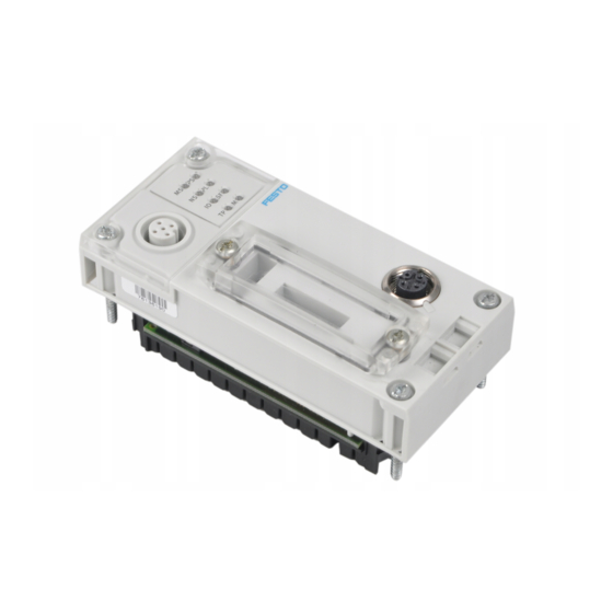
They will help you avoid damage to the electronics. Note Use protective caps or blanking plugs to seal unused connections. This is how you achieve protection class IP65/IP67. Information about mounting of the CPX terminal can be found in the CPX system description (P.BE-CPX-SYS-...). Festo P.BE-CPX-FB32-EN en 1111a... - Page 18 1. Installation Electrical connection and display elements On the fieldbus node CPX-FB32 you will find the following connection and display elements: Bus-status-specific and CPX-specific Service interface for the Hand- LEDs held (V24) Fieldbus interface: Ethernet connection (4-pin M12 socket, D-coded) Transparent cover for the DIL switches Fig.
- Page 19 T10. 2. Pull the fieldbus node carefully and without tilting away from the contact rails of the manifold base. Fieldbus node CPX-FB32 Interlinking block with contact rails Torx T10 screws Fig. 1/2: Dismantling/mounting the fieldbus node Festo P.BE-CPX-FB32-EN en 1111a...
- Page 20 3. Only tighten the screws by hand. Place the screws so that the self-cutting threads can be used. 4. Tighten the screws with a Torx screwdriver size T10 with torque 0.9 ... 1.1 Nm. Festo P.BE-CPX-FB32-EN en 1111a...
-
Page 21: Settings Of The Dil Switches On The Fieldbus Node
1. Place the cover carefully on the node. Note • Make sure that the seal is seated correctly. 2. Tighten the two fastening screws at first by hand and then with a torque of 0.4 Nm. Festo P.BE-CPX-FB32-EN en 1111a... -
Page 22: Settingthe Dil Switches
4. Mount the cover again (section 1.2.1). DIL switch 1: Operating mode DIL switch 2: Diagnostic mode or number of I/O bytes for Remote Controller DIL switch 3: IP addressing Fig. 1/3: DIL switch in the fieldbus node Festo P.BE-CPX-FB32-EN en 1111a... - Page 23 An FEC integrated in the CPX terminal takes DIL 1.2: OFF control of the I/Os. This operating mode is only useful if an FEC is integrated in the CPX terminal. Tab. 1/1: Setting the operating mode with DIL switch 1 Festo P.BE-CPX-FB32-EN en 1111a...
- Page 24 (+ +16 E-bits (8 used)) 2.2: ON Reserved for future extensions 2.1: ON 2.2: ON The I/O diagnostic interface occupies an additional 16 I/O bits. Tab. 1/2: Setting the diagnostic mode with DIL switch 2 (Remote I/O operating mode) 1-10 Festo P.BE-CPX-FB32-EN en 1111a...
- Page 25 16 byte I/16 byte O for communication of 2.1: OFF the fieldbus node with the CPX-FEC or 2.2: ON CPX-CEC. Reserved 2.1: ON 2.2: ON Tab. 1/3: Setting the number of I/O bytes with DIL switch 2 (operating mode Remote Controller) 1-11 Festo P.BE-CPX-FB32-EN en 1111a...
- Page 26 All switches OFF IP address (factory setting) Tab. 1/4: Settings of DIL switch 3 for different types of addressing The factory setting is the dynamic addressing. Observe the detailed information on addressing in section 1.3.3. 1-12 Festo P.BE-CPX-FB32-EN en 1111a...
-
Page 27: Connecting The Ethernet Fieldbus
Also observe the corresponding regulations in EN 60204 Part 1. Applicable for the fieldbus length are the specifications for Ethernet networks according to ANSI/TIA/EIA-568-B.1 1-13 Festo P.BE-CPX-FB32-EN en 1111a... -
Page 28: Fieldbusinterface Of The Cpx-Fb32
4. RX– Received data– Housing: screen Tab. 1/5: Pin assignment of the fieldbus interface of the CPX-FB32 (M12 4pin) Connection with fieldbus plugs from Festo With the fieldbus plug from Festo (type NECU-M-S-D12G4- C2-ET, TN 543109), you connect the CPX terminal to the fieldbus. -
Page 29: Setting The Ip Address
Note When changes are made to the network settings of the CPX-FB32, the Modify LED “M” flashes yellow: • In this case, restart the CPX-FB32 with Power OFF/ON. Dynamic addressing via BOOTP/DHCP Factory setting In the factory setting, all switch elements of the DIL switch 3 are set to OFF and BOOTP/DHCP is activated in the CPX-FB32. - Page 30 Fig. 1/4: Examples of set IP addresses (binary coded) with fixed addressing In case of fixed addressing, the setting of the network mask and the gateway are set unchangeably to: Network mask: 255.255.255.0 Gateway: 0.0.0.0 1-16 Festo P.BE-CPX-FB32-EN en 1111a...
- Page 31 1. Installation Network setting stored in the CPX-FB32 and setting with DIL switches Analogously to the section “Fixed addressing via DIL switches”, the last octet of the IP address is set with the DIL switch 3. But the first 3 octets are not necessarily “192.168.1”, but can be freely selected via the IP address parameter.
-
Page 32: Extended Ethernet Settings
100 MBd Duplex mode The full Duplex mode can be activated/deactivated. 1.3.5 Use Webserver functions of the CPX-FB32 A Webserver is integrated in the CPX-FB32. The Webserver makes available read access to the most important parameters and diagnostic functions. 1-18... -
Page 33: Pin Assignment Of Power Supply
The current consumption of a CPX terminal depends on the number and type of integrated modules and components. Read the information on power supply as well as on the earthing measures to be carried out in the CPX system manual. 1-19 Festo P.BE-CPX-FB32-EN en 1111a... - Page 34 4: Free (not connected) EL/SEN 5: 24 V / 24 V 5: 24 V 7/8”-5POL Operating voltage electronics/sensors EL/SEN Load voltage outputs Load voltage valves Tab. 1/6: Pin assignment for system supply, additional supply and valve supply 1-20 Festo P.BE-CPX-FB32-EN en 1111a...
-
Page 35: Commissioning
Commissioning Chapter 2 Commissioning Festo P.BE-CPX-FB32-EN en 1111a... -
Page 36: Addressing
....2-39 Check list for commissioning the CPX terminal with FB32 ....2-40 Festo P.BE-CPX-FB32-EN en 1111a... -
Page 37: Commissioning
– If you configure the CPX terminal with an EDS file, the field bus node in the first location must be installed as module 0. – The CPX terminal has an address range of up to 64 bytes of inputs and 64 bytes of outputs. Festo P.BE-CPX-FB32-EN en 1111a... -
Page 38: Ascertaining The Address Range
Digital 4-output module CPX-4DA – Digital 8-output module CPX-8DA – Digital 8-output module, high-current CPX-8DA-H 8DO-H – variant Module identification in Handheld 8 bits are always occupied Tab. 2/1: Overview of electric CPX modules (part 1) Festo P.BE-CPX-FB32-EN en 1111a... - Page 39 Number of inputs switchable between 2 and 4 Maximum number (actual allocation depends on the string allocation) With the CPX-FB32, switchable via DIL switches (see 1.2.2) Tab. 2/2: Overview of electric CPX modules (part 2) The address assignment within the individual I/O modules can be found in the manual for the I/O modules.
- Page 40 – 1 ... 24 valve coils 32 O – 1 ... 32 valve coils Additional interfaces in preparation Module identification in Handheld Setting with DIL switches in the pneumatic interface (see description, CPX-EA modules). Tab. 2/3: Overview of pneumatic interfaces Festo P.BE-CPX-FB32-EN en 1111a...
- Page 41 VMPA2-FB-EMG- MPA2G-D – (type 32, 33) with galvanic isolation D2-4 with diagnostic function D2 Additional modules in preparation Module identification in Handheld 8 bits are always assigned Tab. 2/4: Overview of pneumatic modules MPA-S and MPA-F Festo P.BE-CPX-FB32-EN en 1111a...
- Page 42 Tab. 2/5: Overview of pneumatic modules MPA-L The address assignment within the pneumatic modules can be found in the manual for the valve terminal pneumatics. Additional information on MPA pneumatic modules can be found in the description CPX-EA modules (P.BE-CPX-EA-...). Festo P.BE-CPX-FB32-EN en 1111a...
- Page 43 15.Total number of Inputs/Outputs to be configured Total of 1. to 14.: = ∑ _____ I = ∑ _____ O 8 bits are always assigned (4 remain unused). Tab. 2/6: Ascertaining the number of inputs and outputs Festo P.BE-CPX-FB32-EN en 1111a...
-
Page 44: Address Assignment Of The Cpx Terminal
The fieldbus node counts as a module with 0 inputs and 0 outputs if the status bits and the I/O diagnostic interface are deactivated. – The I/Os of different module types are assigned separately from each other. The sequence in the following table applies: 2-10 Festo P.BE-CPX-FB32-EN en 1111a... - Page 45 Status bits and I/O diagnostic interface deactivated Module no.: 0 Fieldbus node CPX-FB32 MPA1 pneumatic modules (8 DO each) MPA pneumatic interface MPA2 pneumatic modules (4 DO each) Fig. 2/1: Example terminal 1: (with MPA1- and MPA2 pneumatic) 2-11 Festo P.BE-CPX-FB32-EN en 1111a...
- Page 46 Tab. 2/8: Addressing the example terminal 1 (see Fig. 2/1) If modular EDS is used, the addresses will be assigned in bytes. In the example above, the output addresses therefore change as from modules 2, 5 and 6. 2-12 Festo P.BE-CPX-FB32-EN en 1111a...
- Page 47 Sensor CPV valve terminal (16DO) on the CP Cylinder interface (string 1) CP output module (16DO) on the CP CP input module (16 DI) interface (string 4) Fig. 2/2: Example terminal 2 (with CP interface) 2-13 Festo P.BE-CPX-FB32-EN en 1111a...
- Page 48 CPX-8DE-8DA MPA1 pneumatic module (8 DO) – O144 ... O151 MPA1 pneumatic module (8 DO) – O152 ... O159 8 bits occupied, 4 bits used Tab. 2/9: Addressing the example terminal 2 (see Fig. 2/2) 2-14 Festo P.BE-CPX-FB32-EN en 1111a...
- Page 49 VTSA pneumatics (type 44) (with DIL 3.2 at ON for status bits) Pneumatic interface (set with DIL switch to 1 ... 8 valve coils) Fig. 2/3: Example terminal 3 (with analogue module and VTSA pneumatics) 2-15 Festo P.BE-CPX-FB32-EN en 1111a...
- Page 50 2. Commissioning Module Module Input address Output address Fieldbus node CPX-FB32 with I0 ... I15 – status bits Digital 8-input module CPX-8DE I16 ... I23 – Digital 8-input module CPX-8DE I24 ... I31 – Digital 4-output module – O32 ... O39...
-
Page 51: Address Assignment After Extension/Conversion
(see Pneumatics description). – Additional interlinking blocks (CPA) of manifold blocks (Midi/Maxi) are inserted between existing ones. – Status bits or the I/O diagnostic interface are activated/deactivated. 2-17 Festo P.BE-CPX-FB32-EN en 1111a... - Page 52 16 O Modified status bits deactivated Modified: Pneumatic interface (set with DIL switch to 1 ... 16 valve Modified: 8DI module replaced by coils) 16DI module Fig. 2/4: Example terminal 3 after extension/modification(compare with Fig. 2/3) 2-18 Festo P.BE-CPX-FB32-EN en 1111a...
- Page 53 2. Commissioning Module Module Input address Output address Fieldbus node CPX-FB32 with Dependent on DIL switch settings deactivated status bits (see Tab. 1/2) Digital 16-input module CPX-16DE I0 ... I15 – Digital 8-input module CPX-8DE I16 ... I23 – Digital 4-output module CPX-4DA –...
-
Page 54: Bus Configuration
The following options are available for expanding an EDS library: – Installing EDS files The EDS file is used only for identification of the CPX-FB32 in the network. – Enter station properties manually (only by using the parameter settings set at the factory). - Page 55 The CPX terminal or the modules will then be represented accordingly in the configuration program. Instructions on installing the EDS files and the icon files can be found in the documentation for your configuration program. 2-21 Festo P.BE-CPX-FB32-EN en 1111a...
- Page 56 – Exclusive Owner Max. 1 – Input only Max. 32 – Listen only Max. 31 (There has to be simultaneously at least 1 Excl.Owner or input only connection) From CPX-FB32 Revision 17 Tab. 2/13: Station features 2-22 Festo P.BE-CPX-FB32-EN en 1111a...
-
Page 57: Overview Of Configuration On The Ethernet/Ip
Nodes with “Major Revision” 2 are downward compatible with “Major Revision” 1 The EDS file suitable to your CPX-FB32 can be determined and downloaded at www.festo.com in the Festo Support Portal. Note If the station features are entered manually, individual parameterisation of the CPX terminal is not possible. -
Page 58: Set Up A Listen-Only Connection
3. Assign the instances of the Assembly Object: Instance 101: Inputs Instance 1 Outputs Instance 102: Configuration data, if used (“Configuration Assembly”) 4. Select the data format Input Data – SINT. 5. Enter the IP address, if necessary. 2-24 Festo P.BE-CPX-FB32-EN en 1111a... -
Page 59: Configuration With Rslogix5000
2. Commissioning 2.2.4 Configuration with RSLogix5000 With the help of the CPX Festo Maintenance Tool (CPX-FMT), it is also possible to export the configuration of a CPX terminal with EtherNet/IP bus node into an RSLogix5000 project (see section 2.3.2). 1. Click in RSLogix5000 in the “I/O Configuration” on the right on the Ethernet/IP bridge and select “New Module”:... - Page 60 2. Commissioning CPX-FB32 – adding as new module in Ethernet/IP Fig. 2/5: Configuration with RSLogix5000 2. Select “ETHERNET MODULE – Generic Ethernet Module” in the window “Select Module Type” and confirm with “OK”: 2-26 Festo P.BE-CPX-FB32-EN en 1111a...
- Page 61 2. Commissioning Fig. 2/6: CPX-FB32 – adding as generic module 3. Enter in the window “Module Properties” (Fig. 2/7): – the name for the fieldbus node (freely selectable) – Instances for inputs: 101 outputs: 100 – Instance for Configuration Assembly: 102 The standard setting is “0”...
- Page 62 • Enter at least 1 for the instances for inputs (2 in Fig. 2/7) • if your CPX terminal does not contain any input modules, activate the status bits with the DIL switches (see Tab. 1/2). 2-28 Festo P.BE-CPX-FB32-EN en 1111a...
-
Page 63: Parameterisation
CPX system description (P.BE-CPX-SYS-...) The module parameters that are available for the various modules can be found in the description of the relevant module (e.g. Description of the CPX pneumatic interfaces and CPX I/O modules (P.BE-CPX-EA-...). 2-29 Festo P.BE-CPX-FB32-EN en 1111a... - Page 64 CPX terminal is replaced during servicing. In these cases, check before replacement to see which settings are required and carry out these settings. 2-30 Festo P.BE-CPX-FB32-EN en 1111a...
- Page 65 2. Commissioning 2.3.1 Methods of parameterisation You can parameterise a CPX terminal with CPX-FB32 various methods. The following table and the following sections provide an overview of the methods. Methods and description Advantages Disadvantages 1. Parameterisation via – Parameters are loaded –...
-
Page 66: Parameterisation Via Configuration Assembly (Method 1)
Further information on creation of the Configuration Assembly can be found at www.festo.com/fieldbus. Simplified parameterisation in RSLogix5000 With the help of the CPX Festo Maintenance Tool (CPX-FMT), it is possible to export the configuration of a CPX terminal with EtherNet/IP bus node into an RSLogix5000 project. - Page 67 File } Export } RSLogix (.L5K) and select a storage location for the L5K file. Fig. 2/8: Export of the L5K file 5. Open the L5K file as a new project in RSLogix5000. This project contains the just configured CPX terminal. 2-33 Festo P.BE-CPX-FB32-EN en 1111a...
- Page 68 2. Commissioning 6. To integrate the CPX terminal into existing RSLogix projects, copy the module with a right click } Copy. Fig. 2/9: Copying the CPX module 2-34 Festo P.BE-CPX-FB32-EN en 1111a...
- Page 69 Fig. 2/10: Inserting the CPX module All necessary settings from CPX-FMT are taken over into the RSLogix project. This includes, among others, the I/O data lengths, the IP configuration and all module and system parameters. 2-35 Festo P.BE-CPX-FB32-EN en 1111a...
-
Page 70: Parameterisation Via Software (Method 2A)
CPX terminal after Power On. Note If the system parameter “System start” has the setting “System start with saved parameterisation and saved CPX expansion”, modified parameter settings in the CPX terminal will become valid immediately after Power On. 2-36 Festo P.BE-CPX-FB32-EN en 1111a... -
Page 71: Parameterisation Via The Plc User Program (Method 3)
1 ... 3 Status and Diagnostic Object 1 ... 40 1 ... 12 Diagnostic Trace Object 1 ... 13 Diagnostic Trace Status Object Tab. 2/15: Overview of Object classes for EtherNet/IP (operating mode Remote I/O) 2-37 Festo P.BE-CPX-FB32-EN en 1111a... -
Page 72: Parameterisation With Eds Files (Method 4)
EDS. The EDS files of the CPX terminal must be contained in the EDS library. The CPX-EDS Version 1.2 is used only for identification of the CPX-FB32 in the network. 2-38 Festo P.BE-CPX-FB32-EN en 1111a... -
Page 73: Notes On Parameters For Idle Mode And Fault Mode
You can determine the status to be assumed for each output channel (output or solenoid coil) separately. The standard setting is “Reset of the output channel”. Further information can be found in the CPX system description. 2-39 Festo P.BE-CPX-FB32-EN en 1111a... -
Page 74: Check List For Commissioning The Cpx Terminal With Fb32
This is to ensure that if the CPX terminal is replaced, the new terminal will also be operated with the desired parameter settings. • Use spot checks if necessary to check the parameterisation, e.g. with the configuration program or with the Handheld. 2-40 Festo P.BE-CPX-FB32-EN en 1111a... -
Page 75: Diagnostics
Diagnostics Chapter 3 Diagnostics Festo P.BE-CPX-FB32-EN en 1111a... - Page 76 ..........3-19 Festo P.BE-CPX-FB32-EN en 1111a...
-
Page 77: Diagnostics
Diagnostics Diagnostic information can be Fast “on site” error detection Description for the via the Hand- shown on the CPX Handheld Handheld held in a user-friendly manner by means of menus. Tab. 3/1: Diagnostics options Festo P.BE-CPX-FB32-EN en 1111a... - Page 78 3. Diagnostics Note Observe that the diagnostic information displayed depends on the parameterisation of the CPX terminal. Festo P.BE-CPX-FB32-EN en 1111a...
-
Page 79: Diagnostics Via Leds
The meaning of the LEDs on the electric modules can be found in the description for the relevant module. LEDs on the fieldbus node CPX-FB32 The LEDs on the cover indicate the operating status of the CPX fieldbus node. - Page 80 The SF LED does not light up. – SF M LED see function number 4402 Lights up only when inputs/outputs are controlled via EtherNet/IP. Steady light: Ready for data transmission Flashing: Data transmission ongoing Tab. 3/2: Normal operating status Festo P.BE-CPX-FB32-EN en 1111a...
-
Page 81: Cpx-Specific Leds
PL (power load) – power load supply (outputs/valves) LED (green) Sequence Status Meaning / error handling No error. Load voltage None applied LED lights up Load voltage at the system Eliminate undervoltage supply or additional supply outside the tolerance LED flashes range Festo P.BE-CPX-FB32-EN en 1111a... - Page 82 The System Failure LED flashes dependent on the applicable error class. Error class 1 (simple error): 1 * flashing, pause time Error class 2 (error): 2 * flashing, pause time Error class 3 (serious error): 3 * flashing, pause time Festo P.BE-CPX-FB32-EN en 1111a...
- Page 83 (see system parameter Force mode; function no. 4402). LED flashes – Network settings have – CPX-FB32 Restart (Power OFF/ON), been modified see also section 1.3.3) The display of the Force function (LED flashes) has precedence over the display of the setting for System start (LED lights up).
- Page 84 Complete or correct the configuration Flashes red Error cannot be rectified Check CPX expansion as well as other LEDs and, if necessary, request service Lights up red CPX terminal is in self-test None Flashes red-green 3-10 Festo P.BE-CPX-FB32-EN en 1111a...
- Page 85 CPX terminal is in self-test None Flashes red/green Test algorithm which ensures that no station numbers are assigned double in the network. The test is usually carried out automatically when the network connection is set up. 3-11 Festo P.BE-CPX-FB32-EN en 1111a...
- Page 86 Check the other LEDs, if necessary forcibly switched off request servicing (perhaps an error which cannot be corrected); one Lights up red or more inputs have an error which cannot be corrected CPX terminal is in self-test None Flashes red/green 3-12 Festo P.BE-CPX-FB32-EN en 1111a...
- Page 87 No Ethernet connection or If necessary check Ethernet Ethernet cable not connection connected LED is off Network connection OK – (Link) LED lights up Data traffic (traffic) – Illumination intensity is dependent on the traffic. LED flashes 3-13 Festo P.BE-CPX-FB32-EN en 1111a...
-
Page 88: Diagnostics Via Status Bits
Tab. 3/3: Overview of status bits If various errors occur simultaneously on different types of modules, these errors cannot be assigned via the status bits. Errors may be uniquely determined through the I/O diagnostics interface or diagnostics via EtherNet/IP access. 3-14 Festo P.BE-CPX-FB32-EN en 1111a... -
Page 89: Diagnosis Via I/O Diagnostic Interface
CPX system description. Diagnosis via I/O diagnostic interface For the fieldbus node CPX-FB32,access to the EtherNet/IP Objects through Explicit Message programming is in principle more appropriate than the use of the I/O diagnostic interface (see Appendix B.1). -
Page 90: Diagnosis Via Ethernet/Ip
The CPX system enables diagnosis via EtherNet/IP. The following diagnostic options are supported here: – Explicit Messaging via Ethernet/IP Master – Diagnosis via user program The I/O diagnostic interface can also be read out here. 3-16 Festo P.BE-CPX-FB32-EN en 1111a... - Page 91 (max. 40 entries) – Detail diagnosis + relative time stamp per error event Diagnostic Trace Status Object – Number of entries in the diagnostic memory – Trace status Tab. 3/5: Diagnostic data with Explicit Messaging 3-17 Festo P.BE-CPX-FB32-EN en 1111a...
- Page 92 Status and Diagnostic an error has occurred Object (133 3. Ascertain relevant module diagnostic data Error number, channel General Parameter type and number of Object Module (101 the faulty channel Tab. 3/6: Possible sequence of diagnosis 3-18 Festo P.BE-CPX-FB32-EN en 1111a...
-
Page 93: Error Handling
PLC stop or fieldbus interruption or malfunction: – Single-solenoid valves move to the basic position. – Double-solenoid valves remain in the current position. – Mid-position valves go into mid-position (pressurized, exhausted or closed, depending on valve type). 3-19 Festo P.BE-CPX-FB32-EN en 1111a... - Page 94 3. Diagnostics 3-20 Festo P.BE-CPX-FB32-EN en 1111a...
-
Page 95: A. Technical Appendix
Technical appendix Appendix A Technical appendix Festo P.BE-CPX-FB32-EN en 1111a... - Page 96 ..........Technical data fieldbus node type CPX-FB32 .
-
Page 97: A.1 Technical Data Fieldbus Node Type Cpx-Fb32
Technical data fieldbus node type CPX-FB32 General information General technical data See CPX system description: – Description P.BE-CPX-SYS-... Protection class according to EN 60 529, CPX-FB32 IP65 / IP67 completely mounted, plug connector, like accessories, plugged in or equipped with protective cap... -
Page 98: A.2 Accessories
– DHCP Baud rate 10/100 MBd, full/half duplex Cable type and length see Ethernet specification according to IEEE 802.3 Accessories Accessories Type Part No. M12 plug for connection to the fieldbus NECU-M-S-D12G4-C2-ET 543109 Tab. A/1: Accessories Festo P.BE-CPX-FB32-EN en 1111a... -
Page 99: B. Ethernet/Ip Objects Of The Cpx-Fb32
Ethernet/IP Objects of the CPX-FB32 Appendix B Ethernet/IP Objects of the CPX-FB32 Festo P.BE-CPX-FB32-EN en 1111a... - Page 100 ......Overview of Ethernet/IP objects of the CPX-FB32 .....
-
Page 101: B.1 Overview Of Ethernet/Ip Objects Of The Cpx-Fb32
B. Ethernet/IP Objects of the CPX-FB32 Overview of Ethernet/IP objects of the CPX-FB32 This chapter describes the representation of the CPX terminal within the Ethernet/IP object model. Some of the information is in English even in the documentation in other languages, so that the original terms of the Ethernet/IP specification can be used uniquely. - Page 102 System Object (Global System Object) CPX specific Status and Diagnostic Object 1 ... 40 Diagnostic Trace Object Diagnostic Trace Status Object Configuration Array Object Tab. B/2: Overview of EtherNet/IP objects of the CPX-FB32 – Part 1 Festo P.BE-CPX-FB32-EN en 1111a...
-
Page 103: Ethernet/Ip Objects Of The Cpx-Fb32
1 ... 48 Discrete Output Fault Mode Object 1 ... 48 Discrete Output Idle State Object 1 ... 48 Discrete Output Idle Mode Object Tab. B/3: Overview of EtherNet/IP objects of the CPX-FB32 – Part 2 Festo P.BE-CPX-FB32-EN en 1111a... - Page 104 Function Output Fault Mode Object 1 ... 48 Function Output Idle State Object 1 ... 48 Function Output Idle Mode Object Tab. B/4: Overview of EtherNet/IP objects of the CPX-FB32 – Part 3 Object class Instances Name Type Slave Size Object CPX specific Tab.
-
Page 105: Objects For Network Settings
CPX system manual. Objects for network settings B.2.1 Port Object Object class: Instances: The Port Object lists the CIP ports available on the device. The Port Object of the CPX-FB32 supports an instance with the ID 2. Attr. Access Description Type... -
Page 106: Tcp/Ip Interface Object
B. Ethernet/IP Objects of the CPX-FB32 B.2.2 TCP/IP Interface Object Object class: Instances: With the TCP/IP Interface Object you can configure the network settings of a device. Attr. Access Description Type Status DOUBLE Configuration Capability DOUBLE Get/Set Configuration Control DOUBLE... -
Page 107: Ethernet Link Object
B. Ethernet/IP Objects of the CPX-FB32 B.2.3 Ethernet Link Object Object class: Instances: Via the Ethernet Link Object you can undertake extended settings for the Ethernet connection (see also section 1.3.4): Attr. Access Description Type Interface Speed DOUBLE Interface Flags... -
Page 108: Objects For The I/O Connection
B. Ethernet/IP Objects of the CPX-FB32 Objects for the I/O connection B.3.1 Assembly Object Object class: Instances: The Assembly Object bundles together Attributes of various Objects, so that the exchange of data with the Objects can take place via one connection. - Page 109 B. Ethernet/IP Objects of the CPX-FB32 Remote I/O operating mode Each data range begins on the LSB (least significant bit) of a word. Instance 101: Input Within the instance “Input Assembly Object” all inputs of the CPX system are transmitted cyclically over the network by means of a communication connection.
- Page 110 B. Ethernet/IP Objects of the CPX-FB32 Instance 100: Output Within the Instance Output in the Assembly Object all outputs of the CPX system will be transmitted over the network by means of one communication connection. The following sequence applies during transmission:...
- Page 111 B. Ethernet/IP Objects of the CPX-FB32 The I/O Objects 102 ... 107 also possess the following attributes: Attribute Entries ... Type Number of data of the BYTE module in BYTE or WORD Data type: BYTE – D1 : BYTE – D2...
- Page 112 B. Ethernet/IP Objects of the CPX-FB32 Remote controller operating mode Each data range begins on the LSB (least significant bit) of a word. Instance 100: Output Instance 100 (Output) possesses the following member list in the operating mode Remote Controller: Obj.
-
Page 113: Objects For System Data And Diagnosis
B. Ethernet/IP Objects of the CPX-FB32 Objects for system data and diagnosis B.4.1 Identity Object Object class: Instances: The Identity Object contains the identification and general information on the CPX-FB32. Attr. Access Description Type Vendor ID WORD Device type WORD... -
Page 114: System Object (For Operating Mode Remote I/O
B. Ethernet/IP Objects of the CPX-FB32 B.4.2 System Object (for operating mode Remote I/O) Object class: Instances: This Object is only available in the operating mode Remote I/O. Attr. Access Description Type Function no. CPX operating mode (bit 0 ... 3) BYTE 0 (bit 0 ... - Page 115 B. Ethernet/IP Objects of the CPX-FB32 Attr. Access Description Type Function no. Fail safe BYTE 1 (bit 0, 1) Specifies whether Fail Safe is active or inactive. 0: inactive 1: active System Idle mode 1 (bit 2, 3) Specifies whether Idle mode is active or inactive.
- Page 116 B. Ethernet/IP Objects of the CPX-FB32 Attr. Access Description Type Function no. Get/Set Monitoring (bit 0 ... 7) BYTE 4401 (bit 0 ... 7) Bit 0: Monitoring SCS (short circuit/ overload sensor supply) Bit 1: Monitoring SCO (short circuit/ overload outputs)
-
Page 117: Status And Diagnostic Object
B. Ethernet/IP Objects of the CPX-FB32 B.4.3 Status and Diagnostic Object Object class: Instances: The status bits and the I/O diagnostic interface are mapped here. Attr. Access Description Type Function Status bits (8 bit) BYTE 1936 Source of error: Bit 0: Valve... -
Page 118: Diagnostic Trace Object
B. Ethernet/IP Objects of the CPX-FB32 B.4.4 Diagnostic Trace Object Object class: Instances: 1 ... 40 An instance is created for each diagnostic entry. Attr. Access Designation Description Type Function no. 3488 + n Marking the first entry after BYTE... - Page 119 B. Ethernet/IP Objects of the CPX-FB32 Attr. Access Designation Description Type Function no. 3488 + n Error number Possible error messages see BYTE n = 10 * d + 8 System Manual chapter 5 Subsequent Number of subsequent BYTE n = 10 * d + 9...
-
Page 120: Diagnostic Trace Status Object
B. Ethernet/IP Objects of the CPX-FB32 B.4.5 Diagnostic Trace Status Object Object class: Instances: Attr. Access Name Type Function Number of trace entries in the diagnostic memory BYTE 3482 (bits 0 ... 7) Status of diagnostic memory BYTE 3483 0: Recording active... - Page 121 B. Ethernet/IP Objects of the CPX-FB32 Attr. Access Name Type Function Get/Set Error number filter BYTE 3484 FN = error number (bits 4, 5) 0: Error number filter inactive (presetting) 1: Record only defined FN 2: Do not record defined FN...
-
Page 122: General Module Parameter Object
B. Ethernet/IP Objects of the CPX-FB32 B.4.6 General Module Parameter Object Object class: Instances: 1 ... 48 Applicable is: Instance number = Module number + 1 This Object enables general access to the module parameters of all existing and future CPX modules. - Page 123 B. Ethernet/IP Objects of the CPX-FB32 Attribute no. Parameters Function no. Byte Word Word 4828 + m * 64 + 0 – See relevant module manual for the parameter 4828 + m * 64 + 1 4828 + m * 64 + 2...
- Page 124 B. Ethernet/IP Objects of the CPX-FB32 Attribute no. Parameters Function no. Byte DWord DWord DWord DWord 4828 + m * 64 + 0 – – – See relevant module manual for the parameter 4828 + m * 64 + 1...
-
Page 125: Force Parameter
B. Ethernet/IP Objects of the CPX-FB32 B.4.7 Force parameter The first word receives the lowest instance number of the relevant Object. The second word receives the second lowest instance number, etc. Object Description Force state digital inputs Force mode digital inputs... - Page 126 B. Ethernet/IP Objects of the CPX-FB32 Composition of the Objects for Force mode Objects Force mode: 109, 111, 117, 119, 125, 127 (see Tab. B/8 ... Tab. B/10) Instances: 1 ... 64, 100, 101 Attr. Access Description Type Get/Set Value for Force mode:...
- Page 127 B. Ethernet/IP Objects of the CPX-FB32 Composition of the Objects for Force state for digital I/O modules Objects Force state: 108, 110 (see Tab. B/8) Instances: 1 ... 64, 100, 101 Attr. Access Description Type Get/Set Value for Force state:...
- Page 128 B. Ethernet/IP Objects of the CPX-FB32 Composition of the Objects for Force state for analogue I/O modules Objects Force state: 116, 118 (see Tab. B/9) Instances: 1 ... 32, 100, 101 Attr. Access Description Type Get/Set Channel 0: WORD Value for Forcing...
- Page 129 B. Ethernet/IP Objects of the CPX-FB32 Composition of the Objects for Force state for technology modules Objects Force state: 124, 126 (see Tab. B/10) Instances: 1 ... 64, 100, 101 Attr. Access Description Type Get/Set Channel 0: BYTE Value for Forcing...
-
Page 130: Fail Safe And Idle Parameters
B. Ethernet/IP Objects of the CPX-FB32 B.4.8 Fail Safe and Idle parameters The first word receives the lowest instance number of the relevant Object. The second word receives the second lowest instance number, etc. Object Description Fault state digital outputs... - Page 131 B. Ethernet/IP Objects of the CPX-FB32 Object Description Fault state outputs technology module Fault mode outputs technology module Idle state outputs technology module Idle mode outputs technology module Tab. B/17: Objects for the Fail Safe and Idle parameters for technology modules...
- Page 132 B. Ethernet/IP Objects of the CPX-FB32 Composition of the Objects for Fault/Idle state for digital output modules Object Fault state: Object Idle state: (see Tab. B/15) Instances: 1 ... 64, 100, 101 Attr. Access Description Type Get/Set Channel 0: BOOL...
- Page 133 B. Ethernet/IP Objects of the CPX-FB32 Composition of the Objects for Fault/Idle state for analogue output modules Object Fault state: Object Idle state: (see Tab. B/16) Instances: 1 ... 64, 100, 101 Attr. Access Description Type Get/Set Channel 0: WORD...
- Page 134 B. Ethernet/IP Objects of the CPX-FB32 Composition of the Objects for Fault/Idle state for technology modules Object Fault state: Object Idle state: (see Tab. B/17) Instances: 1 ... 64, 100, 101 Attr. Access Description Type Get/Set Channel 0: BYTE Value for Fault/Idle state...
-
Page 135: Configuration Array Object
This Object is only available in the operating mode Remote Controller. It contains the number of I/O bytes for communication of theCPX-FB32 with the CPX-FEC or CPX-CEC. Setting is made through DIL switches on the CPX-FB32 (see Tab. 1/3). Attr. -
Page 136: Examples
B. Ethernet/IP Objects of the CPX-FB32 Examples B.5.1 Example: Forcing of inputs In this example the Force mode of an analogue input module is parameterised. Module no.: Instance no.: 1 AI-I Parameterisation: Module CPX-4AE-I, Setting of Force mode for channel 2: Object class 117 (see Tab. - Page 137 B. Ethernet/IP Objects of the CPX-FB32 2. Define value for Force state for channel 2: Objects Force state: 116 (see Tab. B/13) Instance: Attr. Access Parameters Type Get/Set Channel 2: WORD Value for Forcing Number of channels BYTE All channels: values for Force mode ARRAY Tab.
-
Page 138: Example: Parameterisation With The General Module Parameter
B. Ethernet/IP Objects of the CPX-FB32 B.5.2 Example: Parameterisation with the general Module Parameter Object In this example a signal extension time with a digital input module and a lower limit value with an analogue input module are parameterised. Module no.: Instance no.: 1... - Page 139 B. Ethernet/IP Objects of the CPX-FB32 Attribute no. Parameter (module no. 1 in Fig. B/2) Function no. byte Word Word 4828 + m * 64 + 0 – Monitoring the CPX module Bit 0: Behaviour after short circuit/overload 4828 + m * 64 + 1...
- Page 140 B. Ethernet/IP Objects of the CPX-FB32 B-42 Festo P.BE-CPX-FB32-EN en 1111a...
- Page 141 Index Appendix C Index Festo P.BE-CPX-FB32-EN en 1111a...
-
Page 142: C. Index
............Festo P.BE-CPX-FB32-EN en 1111a... - Page 143 ........Festo P.BE-CPX-FB32-EN en 1111a...
- Page 144 ........Festo P.BE-CPX-FB32-EN en 1111a...
- Page 145 ........2-25 Festo P.BE-CPX-FB32-EN en 1111a...
- Page 146 ........1-20 Festo P.BE-CPX-FB32-EN en 1111a...
Need help?
Do you have a question about the CPX-FB32 and is the answer not in the manual?
Questions and answers