
Subscribe to Our Youtube Channel
Related Manuals for Festo CPX-FVDA-P


Summary of Contents for Festo CPX-FVDA-P
- Page 1 CPX terminal Output module CPX-FVDA-P Description Output module CPX-FVDA-P with connection block CPX-M-AB-4-M12X2 -5POLE interlinking block CPX-M-GE-EV-FVO 570844 en 1303a [8023314]...
- Page 3 ......570844 E (Festo AG & Co., 73726 Esslingen, Germany, 2013) Internet: http://www.festo.com E-Mail: service_international@festo.com...
- Page 4 Contents and general instructions ® ® PROFINET IO , PROFIBUS are registered trademarks of the respective trademark owners in certain countries. Festo P.BE-CPX-FVDA-P-EN en 1303a English...
-
Page 5: Table Of Contents
........CPX terminal with output module CPX-FVDA-P . - Page 6 ........Set PROFIsafe parameter of the output module CPX-FVDA-P .
- Page 7 ..........Technical data for output module CPX-FVDA-P .
-
Page 8: Important User Instructions
... means that failure to observe this instruction may result in material damage. In addition, the following pictogram marks passages in the text which describe activities with electrostatically sensitive devices: Electrostatically sensitive devices: Incorrect handling may cause damage to devices. Festo P.BE-CPX-FVDA-P-EN en 1303a English... - Page 9 Recommendations, tips and references to other information sources. Accessories: Specifications on necessary or useful accessories for the Festo product. Environment: Information on the environmentally friendly use of Festo products. Text designations Bullets denote activities that may be carried out in any • desired order.
-
Page 10: General Safety Instructions
Intended use The module can be used as intended to achieve the safety function – Safe shut off of connected consumers if in the off state the connected consumers go into the safe state. VIII Festo P.BE-CPX-FVDA-P-EN en 1303a English... - Page 11 (auxiliary supply) through the connection techno- logy of the module as operating voltage for external compon- ents (24 V). The output module CPX-FVDA-P is a product with safety-rel- evant functions and is intended for installation in machines or automation systems and for use as follows: –...
- Page 12 Contents and general instructions Rules for product configuration – The output module CPX FVDA-P must be used only within the standard version of the Festo CPX terminal. Operation of the module within a variant-P CPX terminal is imper- missible. –...
-
Page 13: Possible Incorrect Application
Note In the following cases, the use of the output module CPX-FVDA-P for formation of safety circuits is not permissible: – in a CPX terminal equipped with a CPX-FEC – in a CPX terminal, that is equipped with a CPX-CEC –... - Page 14 Contents and general instructions Note In the event of damage caused by unauthorised manipula- tion or other than intended use, the guarantee is invalid- ated and the manufacturer is not liable for damages. Festo P.BE-CPX-FVDA-P-EN en 1303a English...
-
Page 15: Attainable Safety Level
Contents and general instructions Attainable safety level With the CPX-FVDA-P, safety functions can be implemented up to: – safety integrity level SIL 3 in accordance with IEC 61508 – Safety integrity level SIL CL 3 in accordance with EN 62061 –... - Page 16 When connecting standard ancillary components, also • observe the specified limit values for temperatures, elec- trical data and torque, etc. Observe the instructions and warnings in this description. • Use the product as described under “Intended use”. • Festo P.BE-CPX-FVDA-P-EN en 1303a English...
-
Page 17: Failures Due To Common Cause (Common Cause Failure - Ccf)
Through the following measures, you ensure that common cause failures are avoided: – Observe operating voltage limits – Comply with temperature range. Service Please consult your local Festo Service agent if you have any technical problems. Festo P.BE-CPX-FVDA-P-EN en 1303a English... -
Page 18: Range Of Application And Certifications
Observe that compliance with the named standards is • limited to the output module CPX-FVDA-P. From the per- spective of the output module, all disconnectable parts of a CPX terminal and/or valve terminal are treated as an external load. -
Page 19: Product Identification
Module identifier Significance – Module identifier 1 ; FVDOP (F=Safety; V=Valves; D=Digital; O=Outputs; P=PROFIsafe) – yellow background 2 for identification of the safety functionality Tab. 0/1: Module identifier (FVDAP) of the output module CPX-FVDA-P XVII Festo P.BE-CPX-FVDA-P-EN en 1303a English... - Page 20 Contents and general instructions The name plate of the output module CPX-FVDA-P shows the following information: Name plate (typical) Significance Rating plate – Type designation 1 – Part number 2 – Revision status (here R01) 3 – Serial number represented as data matrix code 4 –...
- Page 21 J = 2017 K = 2018 L = 2019 M = 2020 Tab. 0/3: Manufacturing year (20-year cycle) Manufacturing month January February March April June July August September October November December Tab. 0/4: Manufacturing month Festo P.BE-CPX-FVDA-P-EN en 1303a English...
-
Page 22: Transport And Storage Conditions
– mechanical loads – impermissible temperatures, – moisture and – aggressive atmospheres. Store and transport the product in its original packaging. • The original packaging offers sufficient protection from typical stresses. Festo P.BE-CPX-FVDA-P-EN en 1303a English... -
Page 23: Instructions On This Description
Instructions on this description This description contains general basic information on the mode of operation, assembly and installation of the switch-off module CPX-FVDA-P in combination with the CPX terminal and refers exclusively to the following revisions of the output module:... -
Page 24: Product Specific Terms And Abbreviations
Passivation type in which only the faulty channel involved is passivated. passivation The module remains integrated. Acknowledgment takes place in CPX-FVDA-P via the image table ( section 1.2.1). CRC signature Check value in the safety telegram of PROFIsafe for checking the integrity of the telegram data (cyclic redundancy check). - Page 25 Switch in the 0 V current path of a channel P-switch switch) Passivation Safety function in which the module CPX-FVDA-P switches off all channels or only defective channels (channel-wise passivation), dependent on the respective error. Instead of the programmed values, the so-called replacement values (0) are then effective.
- Page 26 For voltage to be present at the load, both switches (P- and M-switches) must be closed. For shut-off module, the control of the P- and M-switches of a channel is taken over by different microcontrollers for safety reasons. XXIV Festo P.BE-CPX-FVDA-P-EN en 1303a English...
- Page 27 Wire break detection Function that detects and reports connection errors, such as loads without contact and wire break. For shut-off module this function can be activated or deactivated through parameterisation. Tab. 0/5: Product-specific terms and abbreviations Festo P.BE-CPX-FVDA-P-EN en 1303a English...
- Page 28 Contents and general instructions XXVI Festo P.BE-CPX-FVDA-P-EN en 1303a English...
-
Page 29: System Overview Cpx-Fvda-P
System overview CPX-FVDA-P Chapter 1 System overview CPX-FVDA-P Festo P.BE-CPX-FVDA-P-EN en 1303a English... -
Page 30: Cpx Terminal With Output Module Cpx-Fvda-P
........CPX terminal with output module CPX-FVDA-P . -
Page 31: System Overview Cpx-Fvda-P
CPX terminal with output module CPX-FVDA-P The standard variant of the CPX- terminal can be equipped with the output module CPX-FVDA-P. The module has 3 digital output channels (CH0 ... CH2), which permit safe switching off of the following load voltages: –... - Page 32 CH1: output supplied by 24 V right side ; available through the connection technology of the module CPX-FVDA-P Processors for control and monitoring of the P- and M-switches Fig. 1/1: Circuit diagram of the CPX-FVDA-P power supply concept. Festo P.BE-CPX-FVDA-P-EN en 1303a English...
- Page 33 1. System overview CPX-FVDA-P From the perspective of the output module CPX-FVDA-P, the output channels (CH0 ... CH2) are quasi channel pairs, since in each case two paths are always switched together but in- dependently of each other. One channel forms the positive (P) and one the negative (N) path for a potential-free load voltage supply.
-
Page 34: Design Of The Output Module Cpx-Fvda-P
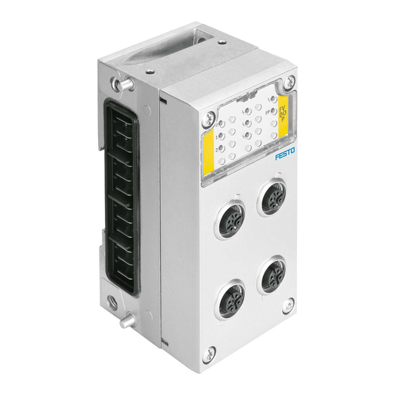
1. System overview CPX-FVDA-P 1.1.1 Design of the output module CPX-FVDA-P The output module CPX-FVDA-P is modularly constructed and consists of the following components: Connection block - here type CPX-M-4-M12X2- 5POL Electronics module CPX-FVDA-P DIL switch for PROFIsafe address Mechanical... - Page 35 – 4 M12 sockets with metal thread, 5-pin – Protection class IP65/IP67 – One functional earth connection per socket – Screening possibility via metal thread – enables the use of M12- and SPEEDCON plug connectors Tab. 1/1: Permissible connection block Festo P.BE-CPX-FVDA-P-EN en 1303a English...
- Page 36 DIL switch. FVDA-P Type Description CPX-FVDA-P – A digital output channel for switching off the load voltage supply line U in the link of the CPX terminals(channel 0) – Two digital output channels (channel 1 and 2) –...
- Page 37 – Mechanical coding prevents plugging in of impermissible modules 1) To the right of the output module, a U is no longer available via the contact rails. Tab. 1/3: Interlinking block Use of a different interlinking block for CPX-FVDA-P is impermissible. Festo P.BE-CPX-FVDA-P-EN en 1303a English...
-
Page 38: Supported Product Designs From Cpx
1. System overview CPX-FVDA-P 1.1.2 Supported product designs from CPX To control of the output module CPX-FVDA-P, a PROFINET- capable bus node is required. The CPX terminal must be equipped with one of the following bus nodes: – CPX-FB33 (Network protocol PROFINET IO) –... -
Page 39: Required Bus Topology (Control Loop System)
CPX terminal with bus node for PROFIBUS or PROFINET IO Safety Configuration Tool (for F-SPS) Embedded PROFIsafe data (black Emergency off switch channel) Output module CPX-FVDA-P PROFINET IO Fig. 1/3: Communication between safety controller and safety module via PROFIsafe 1-11 Festo P.BE-CPX-FVDA-P-EN en 1303a English... - Page 40 In addition to the process data, safety information is transmit- ted in the PROFIsafe telegram. Therefore, the output module CPX-FVDA-P occupies 6 bytes each in the image table of the Fig. 1/4; 3, 4 , 5 ). CPX terminal (...
-
Page 41: Addressing
Address occupation Due to the safety mechanisms of PROFIsafe, the output mod- ule CPX-FVDA-P occupies 6 bytes for inputs and outputs re- spectively in the image table of the CPX terminal. Of these, 4 bytes each are used exclusively for PROFIsafe communica- tion. -
Page 42: Bit Pattern Of The Output And Input Data (F-User Data)
P- and M-side. As a res- ult, the output voltage remains largely unchanged. Poten- tial-free consuming devices are not influenced through this. 1-14 Festo P.BE-CPX-FVDA-P-EN en 1303a English... - Page 43 Uninvolved channels remain uninfluenced and the module remains integrated. Through the input image, in addition to the current status, the module signals the channel error status to the controller Tab. 1/6, channel error status). 1-15 Festo P.BE-CPX-FVDA-P-EN en 1303a English...
- Page 44 0-signals. In case of passivation of a channel, the corresponding bit supplies 0 signal. Tab. 1/6: Bit pattern of the input data (F-user data, byte 0 and byte 1) 1-16 Festo P.BE-CPX-FVDA-P-EN en 1303a English...
- Page 45 Tab. 1/7: Sequence description of channel fault acknowledgment – example The detection of a short circuit is not possible in the passivated status. That is, a present short circuit is no longer reported after passivation. 1-17 Festo P.BE-CPX-FVDA-P-EN en 1303a English...
- Page 46 In case of acknowledgment despite the presence of an error, the channel is automatically passivated again within the de- tection time. If automatic acknowledgment is not desired, the user program must ensure that the F-Host resets the acknow- ledgment. 1-18 Festo P.BE-CPX-FVDA-P-EN en 1303a English...
-
Page 47: Mode Of Operation Of The Output Module
– overvoltage, undervoltage, overload, short circuit and cross circuit – Failure or malfunction of communication via PROFIsafe – Failure or defect of individual safety-determining compon- ents of the module. 1-19 Festo P.BE-CPX-FVDA-P-EN en 1303a English... -
Page 48: Application Ranges (Examples)
(e.g. valves, contactors, relays). – ... of the load voltage of external electronic consumers with safe galvanic isolation of the load voltage. 1) Only for active cross-circuit detection Tab. 1/8: Possible applications for the output module CPX-FVDA-P 1-20 Festo P.BE-CPX-FVDA-P-EN en 1303a English... - Page 49 Safe switch off of potential-free single consumers via CH1 or CH2 (e.g. valves, contactors, relays); For instance an internal or external valve group can be deaer- ated through an external venting valve. Potential-free load Fig. 1/6: Safe switch-off of potential-free individual consumers 1-21 Festo P.BE-CPX-FVDA-P-EN en 1303a English...
- Page 50 24 V supply available from the module Galvanic isolation Fig. 1/7: Safe switch-off of the load voltage of external electronic consumers with safe galvanic isolation of the load voltage 1-22 Festo P.BE-CPX-FVDA-P-EN en 1303a English...
-
Page 51: Requirements For Actuators (Ch0 ... Ch2)
Note If electronic loads are connected to channel 1 and 2, under certain unfavourable operating conditions, incorrect detec- tion of a cross circuit may occur. 1-23 Festo P.BE-CPX-FVDA-P-EN en 1303a English... - Page 52 – Permanent current per unswitched voltage U (auxiliary supply) 2.5 A Further technical data Appendix A.1. Maximum permiss- ible load inductivity at the output channels CH1 and CH2 Fig. A/1. 1-24 Festo P.BE-CPX-FVDA-P-EN en 1303a English...
-
Page 53: Installation
Installation Chapter 2 Installation Festo P.BE-CPX-FVDA-P-EN en 1303a English... - Page 54 ..... . . 2.3.1 Pin allocation with M12 connection block ....Festo P.BE-CPX-FVDA-P-EN en 1303a English...
-
Page 55: General Instructions On Installation
Connection of actuators to the connection block. In this way, e.g. when the electronics module is replaced, the plugs and cables remain mounted in the connection block. Festo P.BE-CPX-FVDA-P-EN en 1303a English... - Page 56 Instructions can be found on the following pages and in the Appendix A.2. Use plugs from the Festo assortment for connection www.festo.com/catalogue). The max. permissible line length is 200 m.
-
Page 57: Electrical Connection And Display Components
Channel error LED for each channel (red) Module error LED (red) FP-LED (green) Module identifier FVDOP (for type CPX-FVDA-P) Electrical connections X1 ... 4 Fig. 2/1: Display and connecting elements CPX-FVDA-P Detailed information on the LEDs section 4.3. Festo P.BE-CPX-FVDA-P-EN en 1303a English... -
Page 58: Pin Allocation With M12 Connection Block
Note Sockets X1 to X4 on the connection block are marked ac- cordingly. The numbering of the sockets here corresponds to the output addresses. CPX-FVDA-P with connection block CPX-M-AB-4-M12X2-5POL Connection block Pin allocation X1, X2 Pin allocation X3, X4 Socket X1... -
Page 59: Commissioning
Commissioning Chapter 3 Commissioning Festo P.BE-CPX-FVDA-P-EN en 1303a English... - Page 60 ........Set PROFIsafe parameter of the output module CPX-FVDA-P .
-
Page 61: Commissioning
The basic procedure and the required configuration data are presented in the following pages. Device master file (GSDML) In combination with the output module CPX-FVDA-P, you need a current device master file GSDML for configuration and programming. Festo P.BE-CPX-FVDA-P-EN en 1303a English... - Page 62 (e.g. set F-parameter). Configuration, parametrisation and commissioning of the CPX terminal with CPX-FVDA-P is dependent on the control system used. Basic information are listed below. Detailed information can be found in the documentation of the control system used and in the online help of the configuration software used.
-
Page 63: Commissioning
For that reason, the module must be restarted to accept the changed address through a new switch-on of the load voltage U ! Information on address allocation by con- figuration software can be found in the documentation of the software used. Festo P.BE-CPX-FVDA-P-EN en 1303a English... - Page 64 2 + 64 + 512 = 578 Decimal value at setting to ON Calculation example – DIL-switch element 2, 7 and 0 (10) to ON Fig. 3/1: 10-element DIL switch for setting the PROFIsafe address – binary coded Festo P.BE-CPX-FVDA-P-EN en 1303a English...
- Page 65 When mounting, observe the instruction in section 5.2 (threaded connector without distortion, clean connection surfaces etc.). 4. Remount the connection block. Tightening torque 0.9 ... 1.1 Nm. Festo P.BE-CPX-FVDA-P-EN en 1303a English...
-
Page 66: Commissioning Steps
If necessary, set standard parameters of the output module ( section 3.4 and 3.4.1) 3. Create and load the safety program 4. Commission CPX terminal on fieldbus (PROFINET IO) and test performance in trial mode. Festo P.BE-CPX-FVDA-P-EN en 1303a English... -
Page 67: Set Profisafe Parameter Of The Output Module Cpx-Fvda-P
3. Commissioning Set PROFIsafe parameter of the output module CPX-FVDA-P PROFIsafe-specific parameters can be viewed or set with the configuration device or of the F-Host (e.g. HW Config). They are marked in accordance with the PROFIsafe profile in the GSDML file. As a result, access is possible only after the pass- word is entered in the F-Host. -
Page 68: Cpx Module Parameter Of The Output Module Cpx-Fvda-P
Tab. 3/3: PROFIsafe parameters CPX module parameter of the output module CPX-FVDA-P The characteristics of the output module CPX-FVDA-P can be parametrised. Parameters that influence diagnostic or error messages refer only to the diagnostic system of CPX and not on the diagnostic channels of the safety protocol. - Page 69 CPX system description or the description of the bus node. The following table provides an overview of the available CPX module parameters of the output module. Overview of module parameters CPX-FVDA-P Function number Module parameters Presetting 4828 + m * 64 + 0...
-
Page 70: Cpx Module Parameters Cpx-Fvda-P In Detail
3. Commissioning 3.4.1 CPX module parameters CPX-FVDA-P in detail Module parameter: monitoring of supply voltage U Handheld 4828 + m * 64 + 0 Function no. m = Module number (0 ... 47) Description This parameter influences the diagnostic behaviour of the module in detection of... - Page 71 But the wire break monitoring function can be activated or deactivated with the monitoring wire break parameter ( Tab. 3/7). – With module-specific error messages, diagnostic messages from the failsafe protocol are not suppressed. Tab. 3/6: General diagnostics 3-13 Festo P.BE-CPX-FVDA-P-EN en 1303a English...
- Page 72 If monitoring is active and a wire break occurs, the error LED of the corresponding channel flashes. If monitoring is switched off, any diagnostic message present is reset. Tab. 3/7: Monitoring wire fracture (channel-specific) 3-14 Festo P.BE-CPX-FVDA-P-EN en 1303a English...
- Page 73 SW 9 SW 8 high byte 0: switch element is OFF 1: switch element is ON Comment This parameter can only be changed by changing the DIL switch setting (read only). Tab. 3/8: DIL switch setting 3-15 Festo P.BE-CPX-FVDA-P-EN en 1303a English...
-
Page 74: Parameterisation And Signal Display With The Handheld (Mmi)
Module identifier in the main menu Module identifier in the header of the (here as third module) system sub-menu for a module Fig. 3/2: Module identifier of the output module CPX-FVDA-P on the handheld unit 3-16 Festo P.BE-CPX-FVDA-P-EN en 1303a English... - Page 75 Monitoring (M) Parameters (P) – basic representation Diagnostics (D) Module Data (MD) Fig. 3/3: Special representations for CPX-FVDA-P on the handheld When the command [Monitoring/Forcing (M)] is called up, the statuses of the 3 channels are displayed. 3-17 Festo P.BE-CPX-FVDA-P-EN en 1303a English...
-
Page 76: Notes On Operation
Boot (start) the F-system – Errors in the safety-oriented communication (PROFIsafe communication errors) – internal faults that are detected by self-tests (e.g. under- voltage) – detectable error situation outside the module (short circuit, cross circuit) 3-18 Festo P.BE-CPX-FVDA-P-EN en 1303a English... -
Page 77: Configuration With Siemens Step 7 (Example)
CPX terminal. The information in the following sections refers exclusively to the output module CPX-FVDA-P. After you have installed the GSDML file and added the CPX terminal with the configuration software (HW Config) to the project’s network, you can add the output module to the con-... - Page 78 3. Commissioning Output module CPX-FVDA-P in the hardware catalogue Output module CPX-FVDA-P in the configuration table of the CPX terminal Start addresses of the output module for inputs and outputs (here 44) Fig. 3/4: CPX terminal configuration with Siemens STEP 7 – HW Config 3-20 Festo P.BE-CPX-FVDA-P-EN en 1303a English...
- Page 79 Observe that not all PROFIsafe parameters shown here are relevant for the output module. Detailed information on the individual parameters can be found in section 3.4.1. Fig. 3/5: Standard parameters of the output module CPX-FVDA-P 3-21 Festo P.BE-CPX-FVDA-P-EN en 1303a English...
- Page 80 [F_Dest_Add] ( the following image). The setting must match the DIL switch setting on the module ( Fig. 3/1). Detailed information on the individual parameters can be found in section 3.3. Fig. 3/6: PROFIsafe parameters 3-22 Festo P.BE-CPX-FVDA-P-EN en 1303a English...
- Page 81 F-user data (each 2 bytes inputs and outputs) Output module CPX-FVDA-P (each 6 bytes of inputs and outputs) Not usable range (each 1 byte for status/control and 3 bytes CRC) Fig. 3/7: Addressing example 3-23 Festo P.BE-CPX-FVDA-P-EN en 1303a English...
- Page 82 VABV-S4-1-T2... – VTSA: pneumatics module – – VABV-S4-2-T2... ) The number of allocated output addresses is specified by DIL switches (here 8DO) Tab. 3/9: Input and output addresses for the example ( Fig. 3/7) 3-24 Festo P.BE-CPX-FVDA-P-EN en 1303a English...
-
Page 83: Diagnostics And Error Handling
Diagnostics and error handling Chapter 4 Diagnostics and error handling Festo P.BE-CPX-FVDA-P-EN en 1303a English... - Page 84 ........Possible error messages of the output module CPX-FVDA-P .
-
Page 85: Diagnostics And Error Handling
CPX bus node Tab. 4/1: Diagnostics options Specific errors of the output module CPX-FVDA-P are reported or suppressed dependent on the module parameterisation. Reported errors can be evaluated, depending on the bus pro- tocol used. The errors are shown on-site via the Error LEDs and, if necessary, can be evaluated with the Handheld. -
Page 86: Possible Error Messages Of The Output Module Cpx-Fvda-P
4. Diagnostics and error handling Possible error messages of the output module CPX-FVDA-P Note Always replace the module in case of an internal defect! • Send defective modules to Festo (product monitoring). • Ensure traceability of the device. Error no. Handheld... - Page 87 1) All channels of the module are passivated (CH0 ... CH2 are switched off) 2) If “channel-wise passivation” is active, only the affected channel is passivated. Otherwise foot- note 1) applies. 3) Does not lead to safety switch-off Tab. 4/2: Possible error messages Festo P.BE-CPX-FVDA-P-EN en 1303a English...
-
Page 88: Diagnostics Via Leds
Status LED (yellow); one per channel Fig. 4/1: LED display of the output module CPX-FVDA-P In the run-up phase, the error LEDs light up for approx. 500 ms. In normal operating status, the following LEDs light up: –... - Page 89 LED flashes Cross circuit at the output Remedy cross- and / or short circuit / or short circuit/overload overload error at the output (dependent on error illuminated number) Tab. 4/4: Channel error LED Festo P.BE-CPX-FVDA-P-EN en 1303a English...
- Page 90 – Safety parameterisation invalid. – CRC error PROFIsafe The PROFIsafe communication parameter cannot be constructed. – Failsafe protocol active – Module communicates with an F-Host via PROFIsafe protocol. illuminated Tab. 4/6: FP-LED Festo P.BE-CPX-FVDA-P-EN en 1303a English...
-
Page 91: Error Handling And Parameterisation
65, 66, 67, 69 Undervoltage Self-test error Error no. 61 overvoltage Parameter “Monitoring of Parameter “General diagnostics undervoltage in valves” module” Parameter “General diagnostics Failsafe protocol” Fig. 4/2: Principle of error handling and parameterisation – part 1 Festo P.BE-CPX-FVDA-P-EN en 1303a English... - Page 92 Error no. 68 Cross circuit Cross circuit channel 0 channel 1 ... 2 Module parameters (switch position represented = default setting) Channel-specific error Fig. 4/3: Principle of error handling and parameterisation – part 2 4-10 Festo P.BE-CPX-FVDA-P-EN en 1303a English...
-
Page 93: Behaviour During The Switch-On Phase (Startup Phase)
Status FP-LED Channel Module Event/ status error error illustration Channel is switched on Channel is switched off Refers to the channel that is assigned to the respective status LED. Tab. 4/8: Normal operating status 4-11 Festo P.BE-CPX-FVDA-P-EN en 1303a English... - Page 94 2) If “channel-wise passivation” is active, only the affected channel is passivated. Otherwise footnote 1) applies. 3) Does not lead to safety switch-off 4) In many cases, the 3 channel-error LEDs are also illuminated. Tab. 4/9: Behaviour in the event of an error 4-12 Festo P.BE-CPX-FVDA-P-EN en 1303a English...
-
Page 95: Diagnostics Via The Cpx Bus Node
Select “Diagnostics” menu (module 3 here) Current module error (here: none) Fig. 4/4: Module identifier of the output module CPX-FVDA-P on the handheld unit In addition, the handheld also provides access to the diagnostic memory. Further information can be found in the description for handheld type P.BE.CPX-MMI-1-... - Page 96 4. Diagnostics and error handling 4-14 Festo P.BE-CPX-FVDA-P-EN en 1303a English...
-
Page 97: Dismantling, Assembly, Repair And Disposal
Dismantling, assembly, repair and disposal Chapter 5 Dismantling, assembly, repair and disposal Festo P.BE-CPX-FVDA-P-EN en 1303a English... - Page 98 ............Festo P.BE-CPX-FVDA-P-EN en 1303a English...
-
Page 99: Dismantling, Assembly, Repair And Disposal
5. Dismantling, assembly, repair and disposal General instructions To avoid errors in mounting, both the interlinking block CPX-M-GE-EV-FVO and the electronics module CPX-FVDA-P are mechanically coded. The coding prevents a different module from being plugged into the interlinking block or the module from being plugged into an incorrect interlinking block. - Page 100 Note that the module must always be installed as the last electronics I/O module next to the right end plate and/or next to a pneumatic interface. – Use the module only in combination with permissible product designs of the CPX terminal ( section 1.1.2). Festo P.BE-CPX-FVDA-P-EN en 1303a English...
-
Page 101: Dismounting And Mounting The Electronics Module
Fig. 1/2 in section 1.1.1. 1. Switch off the operating and load voltage supplies. 2. Unscrew the screws 9 and carefully lift off the sub-base 3. If necessary, pull the electronic module 2 carefully out of the contact rails. Festo P.BE-CPX-FVDA-P-EN en 1303a English... - Page 102 1. Switch off the operating and load voltage supplies. 2. Align the electronic module correctly and press it carefully into the interlinking block 5. 3. Check the seal and sealing surfaces and align and refit the connection block. Festo P.BE-CPX-FVDA-P-EN en 1303a English...
-
Page 103: Repair
5.2. Disposal The material used in the packaging has been specifically chosen for its recyclability. For the final disposal of the electronics module, please con- tact a certified waste management company for electronic waste. Festo P.BE-CPX-FVDA-P-EN en 1303a English... - Page 104 5. Dismantling, assembly, repair and disposal Festo P.BE-CPX-FVDA-P-EN en 1303a English...
- Page 105 Technical appendix Appendix A Technical appendix Festo P.BE-CPX-FVDA-P-EN en 1303a English...
- Page 106 ..........Technical data for output module CPX-FVDA-P .
-
Page 107: Technical Appendix
A. Technical appendix Technical data for output module CPX-FVDA-P CPX-FVDA-P Technical data General technical data of the CPX terminal CPX system description (P.BE-CPX-SYS...) Electric characteristic values – Nominal operating voltage DC [V DC] – Permissible voltage fluctuations -15 ... +20 –... -
Page 108: Technical Appendix
– Cyclic check for cross circuit – Time for reaction to internal error [ms] < 100 – Response time for external channel errors [ms] < 220 – Response time to shut-off command (typ.) [ms] < 10 Festo P.BE-CPX-FVDA-P-EN en 1303a English... - Page 109 – Operating ambient temperature [°C] - 5... + 50 – Ambient temperature in storage [°C] -20...+ 70 – Relative air humidity (non-condensing) 5 ... 90 – Protection class to EN 60 529 Depending on connection block Tab. A/2) Festo P.BE-CPX-FVDA-P-EN en 1303a English...
-
Page 110: Technical Data For Output Module Cpx-Fvda-P
2) Profile for Safety Technology on PROFIBUS DP and PROFINET IO; Version 2.4, March 2007 Tab. A/1: Technical data for output module CPX-FVDA-P Fig. A/1: Maximum permissible load inductivity at the output channels CH1 and CH2 Festo P.BE-CPX-FVDA-P-EN en 1303a English... -
Page 111: Technical Data Of The Connection Block
1) Metal design 2) General technical data of the CPX terminal: CPX system description P.BE-CPX-SYS... 3) Degree of protection is determined through a combination of interlinking block and connection block Tab. A/2: Technical data - connection block Festo P.BE-CPX-FVDA-P-EN en 1303a English... -
Page 112: Technical Data - Interlinking Block
Die-cast aluminium Function Interrupts all contact rails for load voltage supplies switchable, U permanent) Special feature Mechanical coding prevents plugging in of impermissible modules 1) Metal design Tab. A/3: Technical data for interlinking block CPX-M-GE-EV-FVO Festo P.BE-CPX-FVDA-P-EN en 1303a English... - Page 113 Index Appendix B Index Festo P.BE-CPX-FVDA-P-EN en 1303a English...
-
Page 114: Index
............Festo P.BE-CPX-FVDA-P-EN en 1303a English... - Page 115 ........XXII Cross-shorting monitoring ....XXII, 1-14 Festo P.BE-CPX-FVDA-P-EN en 1303a English...
- Page 116 ......... Festo P.BE-CPX-FVDA-P-EN en 1303a English...
- Page 117 3-11, 3-12 Wire break ......3-11, 3-14 Festo P.BE-CPX-FVDA-P-EN en 1303a English...
- Page 118 ........Festo P.BE-CPX-FVDA-P-EN en 1303a English...
- Page 119 ....... . . 3-14, 4-4 Festo P.BE-CPX-FVDA-P-EN en 1303a English...
Need help?
Do you have a question about the CPX-FVDA-P and is the answer not in the manual?
Questions and answers