Festo CPX-FB13 Brief Description
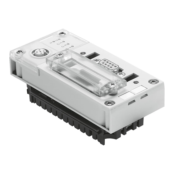
Cpx-terminal field bus node
Hide thumbs
Also See for CPX-FB13:
- Manual (167 pages) ,
- Electronic manual (153 pages) ,
- User instructions (62 pages)

Subscribe to Our Youtube Channel
Related Manuals for Festo CPX-FB13


Summary of Contents for Festo CPX-FB13
- Page 1 CPX-Terminal Kurz- beschreibung Brief description CPX-Feldbus- knoten Typ CPX-FB13 CPX field bus node type CPX-FB13 – Deutsch – English – Español – Français – Italiano – Svenska 653 582 0201NH...
-
Page 2: Table Of Contents
......... . . Edition: 0201NH Original: de © (Festo AG & Co., D-73726 Esslingen, Germany, 2002) Internet: http://www.festo.com E-Mail: service_international@festo.com... -
Page 3: Deutsch
BenutzerhinweiseDeutsch Der Feldbusknoten CPX-FB13 für CPX-Terminals ist aus- schließlich für den Einsatz als Teilnehmer am PROFIBUS- DP bestimmt. Hierbei sind die angegebenen Grenzwerte der technischen Daten einzuhalten. Ausführliche Informationen finden Sie in der Beschreibung zum Feldbusknoten P.BE-CPX-FB13-.. sowie in der CPX-Systembeschreibung P.BE-CPX-SYS-.. . - Page 4 Power Load (grün) System Failure (rot) Modify (gelb, Parametrie- rung geändert oder Forcen rung geändert oder Forcen aktiv) Im normalen Betriebszustand leuchten alle grünen LEDs, die gelben und roten LEDs leuchten nicht. Ohne Feldbusverbindung blinkt die LED BF. Festo CPX-FB13 0201NH Deutsch...
- Page 5 Installationshinweise 3.1 Montage Der Feldbusknoten CPX-FB13 ist in einen Verkettungsblock des CPX-Terminals montiert. Schrauben, Anzugsdrehmoment 0,9 ... 1,1 Nm Feldbusknoten CPX-FB13 Stromschienen Verkettungsblock Demontage: Schrauben herausdrehen und Feldbusknoten vorsich- tig abheben. Montage: 1. Dichtung und Dichtflächen prüfen und Anschlussblock wieder aufsetzen.
- Page 6 Stationsnummer ein: 8fach Schalter- Funktion DIL-Schalter element ON: Gerätebezogene Diagnose aktiv OFF: Gerätebezogene Diagnose inaktiv 1 ... 7 Binär kodierte Eingabe der Stations- nummer. Beispiel im Bild links: 2 + 4 + 32 = Stationsnummer 38 Festo CPX-FB13 0201NH Deutsch...
- Page 7 3.3 Pin-Belegung Bus-Schnittstelle Buchse Pin-Nr. Festo Sub-D-Stecker FBS-SUB-9-GS-9 (IP65) 1. Schirm 2. n.c. 3. RxD/TxD-P 4. CNTR-P 5. DGND 6. VP 7. n.c. 8. RxD/TxD-N 9. n.c. Gehäuse: Schirm Kabelschelle Festo CPX-FB13 0201NH Deutsch...
- Page 8 Verkettungsblock mit System- Lastspannung für Ventile einspeisung Typ CPX-GE-EV-S Betriebsspannung für Verkettungsblock ohne Einspei- Elektronik und Sensoren sung Typ CPX-GE-EV Lastspannung für digitale Verkettungsblock mit Zusatz- Ausgänge einspeisung Typ CPX-GE-EV-Z Funktionserde FE (Pin 1 nicht belegt) Festo CPX-FB13 0201NH Deutsch...
- Page 9 Typ CPX-GE-EV-S Typ CPX-GE-EV-... 1. Betriebsspan- 1. frei nung Elektronik (not connected) und Sensoren 2. Lastspannung 3. 0 V EL/SEN 2. Lastspannung 4. Erdungs- Ventile und anschluss Ausgänge 3. 0 V 4. Erdungs- anschluss Festo CPX-FB13 0201NH Deutsch...
- Page 10 3 1 2 4 Potenzialausgleich Anschluss der System- einspeisung Typ Externe Sicherungen CPX-GE-EV-S Lastversorgung der Ventile/Aus- Anschluss der Zusatz- gänge ist getrennt abschaltbar einspeisung für elektri- sche Ausgänge Erdungsanschluss Pin 4, ausgelegt Typ CPX-GE-EV-Z für 16 A Festo CPX-FB13 0201NH Deutsch...
- Page 11 CPX-Terminals im Servicefall nicht selbsttätig durch das übergeordnete System hergestellt. Überprüfen Sie in diesem Fall vor dem Austausch, welche Einstellungen erforderlich sind, und stellen Sie diese Einstellungen her. Detaillierte Hinweise finden Sie in der Feldsbusknoten- Beschreibung P.BE-CPX-FB13-... bzw. der Beschreibung Ihres Handhelds. Festo CPX-FB13 0201NH Deutsch...
- Page 12 (nur CPX-FB13) EL/SEN Feldbus – Protokoll PROFIBUS-DP – Ausführung RS 485, potentialfrei – Übertragungsart Seriell asynchron, halb- duplex – Galvanische Trennung Busschnittstelle opto- entkoppelt – Übertragungsgeschwindigkeit 9,6...12000 kBaud, automa- tische Baudratenerkennung – Kabeltyp Abhängig von Leitungslänge Festo CPX-FB13 0201NH Deutsch...
-
Page 13: English
User instructionsEnglish The field bus node CPX-FB13 for CPX terminals is intended exclusively for use as a slave on the PROFIBUS-DP. The maximum values specified in the section “Technical specifications” must be observed here. Detailed informa- tion can be found in the manual for the field bus node P.BE-CPX-FB13-.. - Page 14 Force trizing modified or Force active) In normal operating status all green LEDs light up; the yellow and red LEDs do not light up. If there is no field bus connection, the LED BF will flash. Festo CPX-FB13 0201NH English...
- Page 15 Installation instructions 3.1 Fitting Field bus node CPX-FB13 is mounted in a manifold sub- base of the CPX terminal. Screws, tightening torque 0.9...1.1 Nm Field bus node CPX-FB13 Contact rails Manifold sub-base Dismantling Remove the screws and carefully lift up the field bus node.
- Page 16 8-element DIL switch: 8-element Switch Function DIL switch element ON: Device-related diagnosis active OFF: Device-related diagnosis inactive 1...7 Binary-coded station number entry. Example on left in diagram: 2 + 4 + 32 = station number 38 Festo CPX-FB13 0201NH English...
- Page 17 3.3 Pin assignment of bus interface Socket Pin no. Festo sub-D plug FBS-SUB-9-GS-9 (IP65) 1. Screening/shield 2. n.c. 3. RxD/TxD-P 4. CNTR-P 5. DGND 6. VP 7. n.c. 8. RxD/TxD-N 9. n.c. Housing: Screening/shield Cable clip Festo CPX-FB13 0201NH English...
- Page 18 Load voltage for valves supply type CPX-GE-EV-S Operating voltage for the Manifold sub-base without electronics and sensors supply type CPX-GE-EV Load voltage for digital Manifold sub-base with outputs additional supply type Functional earth (FE) CPX-GE-EV-Z (pin 1 not assigned) Festo CPX-FB13 0201NH English...
- Page 19 CPX-GE-EV-S CPX-GE-EV-... 1. Operating 1. not connected voltage supply for electronics and sensors EL/SEN 2. Load voltage 2. Load voltage for valves and outputs 3. 0 V 3. 0 V 4. Earth/ground 4. Earth/ground connection connection Festo CPX-FB13 0201NH English...
- Page 20 External fuses CPX-GE-EV-S The load voltage of the valves/ Connection of outputs can be switched off additional supply for separately electric outputs type CPX-GE-EV-Z Earth connection pin 4 is designed for 16 A Festo CPX-FB13 0201NH English...
- Page 21 Detailed instructions can be found in the manual for the field bus node P.BE-CPX-FB13-... or in the manual for your handheld. Festo CPX-FB13 0201NH English...
- Page 22 (Protected Extra-Low contact as per EN 60204-1/IEC 204) Voltage) Internal current consumption at 24 V – From operating voltage supply for electronics/sensors (V Max. 200 mA (only CPX-FB13) EL/SEN Field bus – Protocol PROFIBUS-DP – Design RS 485, floating –...
-
Page 23: Español
Instrucciones para el usuario Español El nodo de bus de campo CPX-FB13 para terminales CPX está destinado exclusivamente para ser utilizado como slave en el PROFIBUS-DP. Aquí deben observarse los valores máximos indicados en la sección “Especificaciones técnicas”. Puede hallarse información detallada en el manual para el nodo de bus de... - Page 24 Force activo) En estado normal de funcionamiento lucen todos los LEDs verdes; los LEDs amarillo y rojo no lucen. Si no hay conexión al bus de campo, el LED BF parpadea. Festo CPX-FB13 0201NH Español...
- Page 25 Instrucciones de instalación 3.1 Instalación El nodo de bus de campo CPX-FB13 está montado en una placa base distribuidora del terminal CPX. Tornillos, par de apriete 0,9 ... 1,1 Nm Nodo de bus de campo CPX-FB13 Raíles de contacto Placa base...
- Page 26 ON: Diagnosis relacionada con el dispositivo activa OFF: Diagnosis relacionada con el dispositivo inactiva 1...7 Introducción del número de estación codificada en binario. Ejemplo en la figura de la izquierda: 2 + 4 + 32 = estación número 38 Festo CPX-FB13 0201NH Español...
- Page 27 3.3 Asignación de pines en el interface del bus de campo Zócalo Pin nº Clavija Festo sub-D FBS-SUB-9-GS-9 (IP65) 1. Apantallamiento 2. n.c. 3. RxD/TxD-P 4. CNTR-P 5. DGND 6. VP 7. n.c. 8. RxD/TxD-N 9. n.c. Cuerpo: Apantallamiento Clip del cable Festo CPX-FB13 0201NH Español...
- Page 28 Placa base distribuidora sin miento para la electró- alimentación al sistema tipo nica y sensores CPX-GE-EV Tensión de carga para Placa base distribuidora con salidas digitales alimentación adicional tipo Tierra funcional (FE) CPX-GE-EV-Z (pin 1 no asignado) Festo CPX-FB13 0201NH Español...
- Page 29 EL/SEN 2. Tensión de 2. Tensión de carga para carga válvulas y sali- das (V 3. 0 V 3. 0 V 4. Conexión de 4. Conexión de tierra/masa tierra/masa Festo CPX-FB13 0201NH Español...
- Page 30 Fusibles externos CPX-GE-EV-S La tensión de carga de las válvu- Conexión de la alimen- las/salidas puede desconectarse tación adicional para por separado salidas eléctricas tipo CPX-GE-EV-Z Conexión a tierra pin 4, diseñada para 16 A Festo CPX-FB13 0201NH Español...
- Page 31 En estos casos, verificar antes de reemplazar, para ver qué ajustes se necesitan y realizar estos ajustes. Pueden hallarse instrucciones detalladas en el manual del nodo de bus de campo P.BE-CPX-FB13-.. o en el manual del Handheld (terminal de mano). Festo CPX-FB13 0201NH Español...
- Page 32 – Tipo de transmisión Serie asíncrona, half-duplex – Aislamiento eléctrico Interface bus optoacoplado – Baud rate (velocidad de transmisión) 9,6...12000 kBaud, reconoci- miento automático de la velocidad de transmisión – Tipo de cable Depende de la longitud del cable Festo CPX-FB13 0201NH Español...
-
Page 33: Français
Instructions d’utilisationFrançais Le nœud de bus de terrain CPX-FB13 pour terminaux CPX est destiné exclusivement à une utilisation en tant qu’abonné sur le PROFIBUS-DP. Veiller à respecter les valeurs limites indiquées dans le chapitre Caractéristiques techniques. Pour de plus amples informations, se reporter au manuel du noeud de bus de terrain P.BE-CPX-FB13-.. - Page 34 En état de fonctionnement normal, toutes les LED vertes s’allument ; les LED jaunes et rouges sont éteintes. Lorsque le bus de terrain n’est pas raccordé, la LED BF clignote. Festo CPX-FB13 0201NH Français...
- Page 35 Instructions d’installation 3.1 Montage Le noeud de bus de terrain CPX-FB13 est monté dans un bloc de distribution du terminal CPX. Vis, couple de ser- rage 0,9 ... 1,1 Nm. Noeud de bus de terrain CPX-FB13 Rails conducteurs Bloc de distribution Démontage :...
- Page 36 ON : Diagnostic d’appareil activé OFF : Diagnostic d’appareil non activé 1 ... 7 Saisie codée en binaire du numéro de station. Exemple dans la figure de gauche : 2 + 4 + 32 = numéro de station 38 Festo CPX-FB13 0201NH Français...
- Page 37 3.3 Affectation des broches (interface du bus) Connecteur Broche n° Connecteur sub-D Festo FBS-SUB-9-GS-9 (IP65) 1. Blindage 2. n.c. 3. RxD/TxD-P 4. CNTR-P 5. DGND 6. VP 7. n.c. 8. RxD/TxD-N 9. n.c. Corps : Blindage Serre-câble Festo CPX-FB13 0201NH Français...
- Page 38 CPX-GE-EV-S Tension d’alimentation Bloc de distribution sans de l’électronique et des alimentation de type CPX-GE-EV capteurs Bloc de distribution avec Alimentation des sorties alimentation auxiliaire de type CPX-GE-EV-Z (broche 1 Terre du système FE non affectée) Festo CPX-FB13 0201NH Français...
- Page 39 1. Libre (non mentation de connectée) l’électronique et des capteurs EL/SEN 2. Alimentation 2. Alimentation des distribu- principale teurs et des sorties 3. 0 V 3. 0 V 4. Borne de terre 4. Borne de terre Festo CPX-FB13 0201NH Français...
- Page 40 Fusibles externes de type CPX-GE-EV-S L’alimentation des distributeurs/ Raccordement de sorties peut être coupée séparé- l’alimentation auxiliaire ment pour les sorties électri- ques de type Raccordement à la terre, broche 4, CPX-GE-EV-Z prévue pour 16 A Festo CPX-FB13 0201NH Français...
- Page 41 CPX en cas de panne. Dans ce cas, avant l’échange, vérifier quels sont les réglages nécessaires et les effectuer. Pour plus de détails, se reporter au manuel du noeud de bus de terrain P.BE-CPX-FB13-.. ou au manuel de votre console manuelle. Festo CPX-FB13 0201NH Français...
- Page 42 Série, asychrone, demi- duplex – Isolation galvanique Interface par optocoupleur 9,6 ... 12 000 kbauds, recon- – Vitesse de transmission naissance automatique de la vitesse de transmission – Type de câble Selon la longueur de câble Festo CPX-FB13 0201NH Français...
-
Page 43: Italiano
Indicazioni per l’utilizzatoreItaliano Il nodo Fieldbus CPX-FB13 è destinato unicamente all’im- piego come utente del PROFIBUS-DP. Durante il funzionamento si devono rispettare i limiti tec- nici indicati. Per informazioni dettagliate fare riferimento alla descrizione relativa al nodo Fieldbus P.BE-CPX-FB13-.. nonché alla descrizione del sistema CPX P.BE-CPX-SYS-.. . - Page 44 Modify (giallo, parametriz- zazione modificata o forza- zazione modificata o forza- tura attivata) In stato di funzionamento normale tutti i LED verdi sono accesi, quelli gialli e rossi spenti. In assenza di collegamento Fieldbus il LED BF lampeggia. Festo CPX-FB13 0201NH Italiano...
- Page 45 Indicazioni per l’installazione 3.1 Montaggio Il nodo Fieldbus CPX-FB13 è montato in una sottobase del terminale CPX. Viti, coppia di ser- raggio 0,9...1,1 Nm Nodo Fieldbus CPX-FB13 Guide della sottobase Sottobase Smontaggio: Togliere le viti e sollevare con delicatezza il nodo Fieldbus.
- Page 46 (attiva) OFF: Informazione diagnostica riferita all’unità inactive (non attiva) 1 ... 7 Inserimento del numero di stazione codificato in codice binario. Esempio nella figura a sinistra: 2 + 4 + 32 = numero di stazione 38 Festo CPX-FB13 0201NH Italiano...
- Page 47 3.3 Occupazione dei pin dell’interfaccia bus Connettore N. pin Connettore Festo sub-D FBS-SUB-9-GS-9 (IP65) 1. Schermo 2. n.c. 3. RxD/TxD-P 4. CNTR-P 5. DGND 6. VP 7. n.c. 8. RxD/TxD-N 9. n.c. Corpo: Schermo Fascetta serracavi Festo CPX-FB13 0201NH Italiano...
- Page 48 Sottobase con modulo di alimen- Tensione di esercizio tazione sistema tipo CPX-GE-EV per elettronica e sensori Sottobase con modulo supple- Tensione di carico per mentare di alimentazione tipo uscite digitali CPX-GE-EV-Z (Pin 1 non occupato) Messa a terra (FE) Festo CPX-FB13 0201NH Italiano...
- Page 49 1. Libero della tensione (non collegato) di esercizio elettronica/ sensori EL/SEN 2. Tensione di 2. Tensione di carico valvole e carico uscite 3. 0 V 3. 0 V 4. Connessione di 4. Connessione di terra terra Festo CPX-FB13 0201NH Italiano...
- Page 50 Fusibili esterni zione sistema tipo CPX-GE-EV-S Disinserimento separato dell’ alimentazione sotto carico delle Collegamento del valvole/uscite modulo di alimenta- zione supplementare Collegamento di messa a terra per uscite elettriche pin 4 dimensionato per 16 A tipo CPX-GE-EV-Z Festo CPX-FB13 0201NH Italiano...
- Page 51 Prima della sostituzione verificare quali regolazioni siano necessarie ed impo- starle. Per maggiori dettagli fare riferimento alla descrizione del nodo Fieldbus P.BE-CPX-FB13-.. o alla descrizione del Suo Handheld. Festo CPX-FB13 0201NH Italiano...
- Page 52 – Tipo di trasmissione Seriale asincrona, semiduplex – Isolamento galvanico Interfaccia bus con disaccop- piamento optoelettronico – Velocità di trasmissione 9,6 ... 12000 kBaud, rileva- zione automatica della baudrate – Tipo cavo Dipendente dalla lunghezza dei cavi Festo CPX-FB13 0201NH Italiano...
-
Page 53: Svenska
AnvändaranvisningarSvenska Fältbussnod CPX-FB13 för CPX-terminaler är endast av- sedd för att användas som slav på PROFIBUS-DP. De gränsvärden som anges under Tekniska data måste följas. Utförligare information finns i manualen till fält- bussnod P.BE-CPX-FB13-.. samt i CPX-systembeskrivning P.BE-CPX-SYS-.. . Varning S Koppla från spänningen innan stickkontakter ansluts... - Page 54 Power Load (grön) System Failure (röd) Modify (gul, parametrering ändrad eller tvångsstyr- ändrad eller tvångsstyr- ning aktiv) I normalt drifttillstånd lyser alla gröna LED:n. Gula och röda LED:n lyser däremot ej. Utan fältbussförbindelse blinkar LED BF. Festo CPX-FB13 0201NH Svenska...
- Page 55 Installationsanvisningar 3.1 Montering Fältbussnod CPX-FB13 är monterad i ett kopplingsblock på CPX-terminalen. Skruvar, åtdrags- moment 0,9 ... 1,1 Nm Fältbussnod CPX-FB13 Strömskenor Kopplingsblock Demontering: Lossa skruvarna och lyft fältbussnoden försiktigt. Montering: 1. Kontrollera tätning och tätningsytor och sätt på anslut- ningsblocket igen.
- Page 56 Ställ in diagnosläge och stationsnummer med den 8-poliga DIL-omkopplaren: 8-polig DIL- Funktion omkopplare kopplar- element ON: Modulspecifik diagnos aktiv OFF: Modulspecifik diagnos inaktiv 1...7 Binär koderad inmatning av stations- nummer. Exempel i bilden till vänster: 2 + 4 + 32 = stationsnummer 38 Festo CPX-FB13 0201NH Svenska...
- Page 57 3.3 Kontaktkonfiguration bussgränssnitt Honkontakt Stiftnr. Festo sub-D-hankon- takt FBS-SUB-9-GS-9 (IP65) 1. Skärm 2. n.c. 3. RxD/TxD-P 4. CNTR-P 5. DGND 6. VP 7. n.c. 8. RxD/TxD-N 9. n.c. Hus: skärm Kabelklämma Festo CPX-FB13 0201NH Svenska...
- Page 58 0 V FJ 0V FJ n.c. Kopplingsblock med system- Matningsspänning för matning CPX-GE-EV-S ventiler Kopplingsblock utan system- Matningsspänning för matning CPX-GE-EV elektronik och givare Kopplingsblock med extra Matningsspänning för spänningsmatning CPX-GE-EV-Z digitala utgångar (stift 1 ledigt) Funktionsjord FJ Festo CPX-FB13 0201NH Svenska...
- Page 59 CPX-GE-EV-S CPX-GE-EV-... matning 1. Matningsspän- 1. Ledig ning elektronik (not connected) och givare EL/SEN 2. Matningsspän- 2. Matnings- ning ventiler spänning och utgångar 3. 0 V 3. 0 V 4. Jordanslutning 4. Jordanslutning Festo CPX-FB13 0201NH Svenska...
- Page 60 3 1 2 4 3 1 2 4 Potentialutjämning Anslutning av system- matning CPX-GE-EV-S Externa säkringar Anslutning av extra Ventilernas/ugångarnas matnings- spänningsmatning för spänningsförsörjning kan kopplas elektriska utgångar från separat CPX-GE-EV-Z Jordanslutning stift 4, konstruerad för 16 A Festo CPX-FB13 0201NH Svenska...
- Page 61 CPX-terminal byts ut vid un- derhåll. Kontrollera i detta fall innan byte vilka inställ- ningar som är nödvändiga och ställ in motsvarande. Detaljerad information finns i fältbussmanualen P.BE-CPX-FB13-.. resp. i manualen till din handterminal. Festo CPX-FB13 0201NH Svenska...
- Page 62 Fältbuss – Protokoll PROFIBUS-DP – Utförande RS 485, potentialfri – Överföringssätt Seriellt asynkront, halv duplex – Galvanisk isolering Bussgränssnitt optofrån- kopplat – Överföringshastighet 9,6 ... 12.000 kBaud, automatisk avkänning av överföringshastighet – Kabeltyp Beroende av kabellängd Festo CPX-FB13 0201NH Svenska...
Need help?
Do you have a question about the CPX-FB13 and is the answer not in the manual?
Questions and answers