Sign In
Upload
Manuals
Brands
Festo Manuals
Control Unit
CPX-FB14
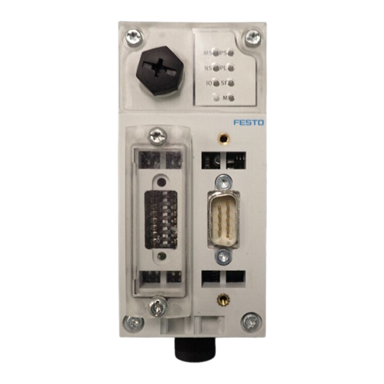
Festo CPX-FB14 Manuals
Manuals and User Guides for Festo CPX-FB14. We have
5
Festo CPX-FB14 manuals available for free PDF download: Description, Electronic Manual, Brief Description
Festo CPX-FB14 Description (182 pages)
Terminal CPX, Bus node, CANopen networkprotocol
Brand:
Festo
| Category:
Control Unit
| Size: 0.89 MB
Table of Contents
Table of Contents
5
Intended Use
8
Service
9
Target Group
9
Instructions Regarding this Description
10
Important User Information
11
1 Installation
15
Installation
16
General Instructions on Installation
17
Installation
17
Settings of the DIL Switches on the Bus Node
22
Removing and Mounting the Cover for the DIL Switches
22
Settingthe DIL Switches
23
Connecting the Fieldbus
37
Fieldbus Cable
37
Fieldbus Baud Rate and Fieldbus Length
38
Information on Connecting the Fieldbus
39
Fieldbus Interface
41
Connecting with the Fieldbus Plug from Festo
42
Further Connection Possibilities for the Fieldbus with Adapters
44
Bus Terminal with Terminating Resistors
47
Install a Terminating Resistor Using the Adapters
47
Power Supply
48
2 Commissioning
49
Commissioning
50
Configuration
50
Layer Setting Service (LSS)
50
Commissioning on a Canopen Master
52
General Information on Canopen
53
Configuration
54
Layer Setting Service (LSS)
54
LSS Commands
54
Configuration of the LSS Slave
72
Addressing the CPX Terminal
74
Configuration Examples
77
Overviews
83
Brief Overview of the Scope of Functions
83
Overview Object Directory
84
Behaviour of the CPX Terminal When It Is Switched on
85
Default Identifier Distribution
87
Object Directories
89
Communication Profile
89
Overview of the PDO Structure
94
Digital Inputs (Transmit PDO 1)
95
Digital Outputs (Receive PDO 1)
98
Analogue Inputs Channel 0
103
Analogue Outputs Channel 0
108
Analogue Inputs Channel 4
110
Analogue Outputs Channel 4
113
Technology Modules, Status Bits, I/O Diagnostic Interface (PDO 4)
116
Manufacturer Specific Profile
120
Overview of Mappingobjects
127
Forcing
129
Function Assignment and Virtual Modules
133
Parameterisation
139
Parameterisation with the Handheld
140
Commissioning the CPX Terminal in the System
141
Correct Commissioning, Normal Operating Status
142
Diagnostics
143
Diagnostics
144
Diagnostics
145
Summary of Diagnostics Options
145
Diagnostics Via Leds
146
Normal Operating Status
147
Displays of the CPX-Specific Leds PS, PL, SF, M
148
Displays of the Canopen-Specific Leds MS, NS, IO
151
Diagnostics Via Status Bits
154
Diagnostics Via the I/O Diagnostic Interface
155
Diagnostics Via Canopen
156
The Emergency Message
157
CPX Error Numbers
162
A. Technical Appendix
168
A.1 Technical Data, Bus Node CPX-FB14
169
A.2 Examples: Communication Sequence
171
A.2.3 Example 3, Start "Node Guard" Monitoring
172
A.2.4 Example 4: Load Objects
173
A.2.5 Example 5: Write Objects
174
B. Index
176
Advertisement
Festo CPX-FB14 Electronic Manual (154 pages)
Terminal Fieldbus Node
Brand:
Festo
| Category:
Touch terminals
| Size: 1.3 MB
Table of Contents
Table of Contents
5
Intended Use
9
Target Group
9
Service
9
Notes on this Manual
10
Important User Instructions
11
Installation
15
Installation
16
General Instructions on Installation
17
Settings of the DIL Switches on the Field Bus Node
21
Removing and Fitting the Cover over the DIL Switches
21
Setting the DIL Switches
22
Connecting the Field Bus
34
Field Bus Cable
34
Field Bus Baud Rate and Field Bus Length
35
Information on Connecting the Field Bus
36
Field Bus Interface
38
Connecting with the Field Bus Plug from Festo
39
Further Connection Possibilities for the Field Bus with Adapters
41
Bus Terminal with Terminating Resistors
44
Install a Terminating Resistor Using the Adapters
44
Pin Assignment of Power Supply
45
Commissioning
47
Commissioning
48
Commissioning on a Canopen Master
49
General Information on Canopen
50
Configuration
51
Addressing the CPX Terminal
51
Configuration Examples
54
Overview
60
Brief Overview of the Scope of Functions
60
Overview Object Directory
61
Reaction of the CPX Terminal When It Is Switched on
62
Default Identifier Distribution
64
Object Directories
66
Communication Profile
66
Overview of the PDO Structure
71
(Pdo 4)
71
Digital Inputs (Transmit PDO 1)
72
Digital Outputs (Receive PDO 1)
74
Analogue Inputs Channel 0 3 (Transmit PDO 2)
79
Analogue Outputs Channel
84
Receive PDO 2)
84
Analogue Inputs Channel
86
Transmit PDO 3)
86
Analogue Outputs Channel
89
Receive PDO 3)
89
Technology Modules, Status Bits, I/O Diagnostic Interface
91
Manufacturer Specific Profile
95
Overview of Mappingobjects
102
Force
104
Function Assignment and Virtual Modules
108
Parameterizing
114
Parameterizing When Switching on
114
Parameterization with the Handheld
115
Application Example for Parameterization
115
Commissioning the CPX Terminal in the System
116
Error−Free Commissioning, Normal Operating Status
116
Diagnosis
117
Diagnosis
118
Diagnosis
119
Overview of Diagnostic Possibilities
119
Diagnostics Via Leds
120
Normal Operating Status
121
Error Displays of the Cpx−Specific Leds PS, PL, SF, M
122
Error Displays of the Canopen−Specific Leds MS, NS, IO
125
Diagnosis Via Status Bits
127
Diagnosis Via the I/O Diagnostic Interface
128
Diagnosis Via Canopen
129
The Emergency Message
130
CPX Fault Numbers
135
A. Technical Appendix
140
Technical Appendix
141
Technical Data of Fieldbus Node CPX−FB14
141
Examples: Communication Sequence
142
Example 1: Start Canopen Network
142
Example 2: Set Output
142
Example 3: Start Node Guard" Monitoring
143
Example 4: Load Objects
144
Example 5: Write Objects
145
Example: Parameterization with the Program Cansetter
146
B. Index
148
Festo CPX-FB14 Electronic Manual (155 pages)
CPX terminal
Brand:
Festo
| Category:
Touch terminals
| Size: 2.38 MB
Table of Contents
Table of Contents
5
Designated Use
8
Target Group
9
Service
9
Notes on the Use of this Manual
10
Important User Instructions
11
1 Installation
15
General Instructions on Installation
18
Setting the DIL Switches on the Field Bus Node
22
Removing and Fitting the Cover for the DIL Switches
22
Setting the DIL Switches
23
Connecting the Field Bus
35
Field Bus Cable
35
Field Bus Baud Rate and Field Bus Length
36
Information on Connecting the Field Bus
37
Field Bus Interface
39
Connecting with Field Bus Plugs from Festo
40
Further Connection Possibilities for the Field Bus with Adapters
42
Bus Termination with Terminating Resistors
45
Install a Terminating Resistor Using the Adapters
45
Pin Assignment of the Power Supply
46
2 Commissioning
49
Commissioning
50
Commissioning on a Canopen Master
52
General Information on Canopen
52
Configuration
54
Addressing the CPX Terminal
54
Configuration Examples with CPA Pneumatics
56
Addressing Examples
60
Overview
63
Brief Overview of the Scope of Functions
63
Overview Object Directory
64
Reaction of the CPX Terminal When It Is Switched on
65
Default Identifier Distribution
67
Object Directories
69
Communication Profile
69
Overview of the PDO Structure
74
Digital Inputs (Transmit PDO 1)
74
Digital Outputs (Receive PDO 1)
77
Analogue Inputs Channel 0 − 3 (Transmit PDO 2)
82
Analogue Outputs Channel 0 − 3 (Receive PDO 2)
87
Analogue Inputs Channel 4 −15 (Transmit PDO 3)
89
Analogue Outputs Channel 4 −15 (Receive PDO 3)
93
Status Bits and I/O Diagnostic Interface (PDO 4)
95
Manufacturer Specific Profile
100
Overview of Mapping Objects
107
Forcen
109
Parametrizing
113
Parametrizing When Switching on
113
Parametrizing with the Handheld
114
Example of Application for the Parametrizing
114
Commissioning of the CPX Terminal in the System
115
Faultless Commissioning, Normal Operating Status
116
Diagnosis
117
Diagnosis
118
Diagnosis
119
Overview of Diagnostic Possibilities
120
Diagnosis Via Leds
121
Normal Operating Status
122
Fault Displays of the Cpx−Specific Leds PS, PL, SF, M
123
Fault Displays of the Canopen−Specific Leds MS, NS, IO
126
Diagnosis Via Status Bits
129
Diagnosis Via the I/O Diagnostic Interface
130
Diagnosis Via Canopen
131
The Emergency Message
132
CPX Fault Numbers
137
A. Technical Appendix
142
Technical Appendix
143
Technical Specifications of Field Bus Node Type CPX−FB14
143
Examples: Communication Sequence
144
Example 1: Start Canopen Network
144
Example 2: Set Output
144
Example 3: Start Node Guard" Monitoring
145
Example 4: Load Objects
146
Example 5: Write Objects
147
Example: Parametrizing with the Program Cansetter
148
B. Index
150
Advertisement
Festo CPX-FB14 Electronic Manual (146 pages)
CPX field bus node
Brand:
Festo
| Category:
Touch terminals
| Size: 2.25 MB
Table of Contents
Table of Contents
5
Designated Use
9
Target Group
10
Service
10
Notes on the Use of this Manual
10
Important User Instructions
11
1 Installation
15
Installation
17
General Instructions on Installation
18
Settings of the DIL Switches on the Field Bus Node
21
Removing and Fitting the Cover over the DIL Switches
21
Setting the DIL Switches
21
Connecting the Field Bus
32
Field Bus Cable
32
Field Bus Baud Rate and Field Bus Length
33
Field Bus Cable
33
Information on Connecting the Field Bus
34
Connecting the Field Bus to the Sub-D Plug
36
Further Connection Possibilities for the Field Bus with Adapters
38
Bus Termination with Terminating Resistors
41
Fitting a Terminating Resistor by Using the Adapters
42
Pin Assignment of Power Supply
43
2 Commissioning
45
Object Directories
46
Digital Inputs (Transmit PDO 1)
46
Digital Outputs (Receive PDO 1)
46
Analogue Outputs Channel 4
46
Status Bits and I/O Diagnostic Interface (PDO 4)
46
Manufacturer Specific Profile
46
Commissioning on a Canopen Master
48
General Information on Canopen
48
Addressing the CPX Terminal
50
Configuration
50
Configuration Example
52
Brief Overview of the Scope of Functions
56
Overviews
56
Overview of the Object Directory
57
Reaction of the CPX Terminal When It Is Switched on
58
Default Identifier Distribution
60
Communication Profile
62
Overview of the PDO Structure
67
Analogue Inputs Channel 0
75
Analogue Inputs Channel 0
80
Analogue Inputs Channel 4...15 (Transmit PDO 3)
82
Analogue Outputs Channel 4
86
Manufacturer Specific Profile
93
Overview of Mapping Objects
99
Force
101
Parametrizing
105
Parametrizing When the Terminal Is Switched on
105
Parametrizing with the Handheld
106
Application Example of Parametrizing
106
Commissioning the CPX Terminal in the System
107
Faultless Commissioning, Normal Operating Status
108
3 Diagnosis
109
Diagnosis
111
Overview of Diagnostic Possibilities
112
Diagnosis Via Leds
113
Normal Operating Status
114
Fault Displays of the CPX-Specifiec Leds PS, PL, SF, M
115
Fault Displays of the Canopen-Specific Leds MS, NS, IO
118
Diagnosis Via Status Bits
121
Diagnosis Via the I/O Diagnostic Interface
122
Diagnosis with Canopen
123
The Emergency Message
124
Fault Numbers
129
Technical Appendix
132
Technical Specifications of Field Bus Node CPX-FB14
133
Examples: Communication Sequence
134
Example 1: Start Canopen Network
134
Example 2: Set Output
134
Example 3: Start "Node Guard" Monitoring
135
Example 4: Load Objects
136
Example 5: Write Objects
137
Example: Parametrizing with the Program "Cansetter
138
Index
140
Festo CPX-FB14 Brief Description (74 pages)
CPX-Terminal field bus node
Brand:
Festo
| Category:
Control Unit
| Size: 1.78 MB
Table of Contents
Table of Contents
2
Deutsch
3
English
15
Español
27
Français
39
Italiano
51
Svenska
63
Advertisement
Related Products
Festo CPX-FB32
Festo CPX-FB23
Festo CPX-FB23-24
Festo CPX-FB39
Festo CPX-FB40
Festo CPX-FB6
Festo CPX-F8DE-P
Festo CPX-FVDA-P2
Festo CPX-FVDA-P
Festo CPX-M-16DE-D
Festo Categories
Industrial Equipment
Control Unit
Controller
Touch terminals
DC Drives
More Festo Manuals
Login
Sign In
OR
Sign in with Facebook
Sign in with Google
Upload manual
Upload from disk
Upload from URL