Festo CPX-FB6 Manual
Cpx fieldbus node
Hide thumbs
Also See for CPX-FB6:
- Electronic manual (138 pages) ,
- Brief description (62 pages) ,
- Translation of the original instructions (12 pages)

Subscribe to Our Youtube Channel
Related Manuals for Festo CPX-FB6


Summary of Contents for Festo CPX-FB6
- Page 1 CPX terminal Description Electronics CPX fieldbus node Type CPX-FB6 Fieldbus protocol: Interbus in accordance with EN 50254 Description 526434 en 1207c [762320]...
- Page 3 ........526434 E (Festo AG & Co. KG, D-73726 Esslingen, 2012) Internet: http://www.festo.com E-Mail: service_international@festo.com...
- Page 4 Contents and general safety instructions ® ® ® INTERBUS , TORX and VDE are registered trademarks of the respective trademark owners in certain countries. Festo P.BE-CPX-FB6-EN en 1207c...
-
Page 5: Table Of Contents
....... . . 2-45 2.2.2 Device parametrisation with the CMD software ....2-49 Festo P.BE-CPX-FB6-EN en 1207c... - Page 6 ..........Technical data bus node type CPX-FB6 .
-
Page 7: Intended Use
• trical isolation of the operating voltage in accordance with IEC/EN 60204-1. Through the use of PELV circuits, protection against electric shock (protection against direct and indirect contact) is en- sured in accordance with IEC/EN 60204-1. Festo P.BE-CPX-FB6-EN en 1207c... -
Page 8: Target Group
This description is intended exclusively for technicians trained in control and automation technology, who have ex- perience in installing, commissioning, programming and dia- gnosing slaves on the Interbus. Service Please consult your local Festo Service if you have any tech- nical problems. Festo P.BE-CPX-FB6-EN en 1207c... -
Page 9: Important User Information
... means that failure to observe this instruction may result in material damage. In addition, the following pictogram marks passages in the text which describe activities with electrostatically sensitive devices: Electrostatically sensitive devices: Incorrect handling may cause damage to devices. Festo P.BE-CPX-FB6-EN en 1207c... - Page 10 Recommendations, tips and references to other information sources. Accessories: Specifications on necessary or useful accessories for the Festo product. Environment: Information on the environmentally friendly use of Festo products. Text designations Bullet points indicate activities which may be carried out • in any sequence.
-
Page 11: Instructions On This Description
(user data are encapsulated by outline data). – Real-time-capable Standards and norms with ref- erence to Interbus: – EN 50254 – IEC 61158 – IEC 61784 Tab. 0/1: Overview, CPX bus node for Interbus Festo P.BE-CPX-FB6-EN en 1207c... - Page 12 (Type 44 and 45) Software status (SW) see name plate Revision identification, see name plate Fig. 0/1: New CPX-FB6 modules supported through the bus node This description contains specific information on installing, commissioning, programming and diagnosing with the CPX bus node for Interbus.
- Page 13 An overview of the structure of the CPX terminal user docu- mentation is contained in the CPX system description. Product-specific information about the control system (IPC, PLC or I/O controller) can be found in the manufacturer's product documentation accompanying the product. Festo P.BE-CPX-FB6-EN en 1207c...
- Page 14 The interface module is the central device for controlling the Interbus data ring. It exchanges the data transported serially in the data ring with the higher-order controller or computer system and the lower-order Interbus stations in both directions acyclically or cyclically. Festo P.BE-CPX-FB6-EN en 1207c...
- Page 15 With baud rates of 500 kBd and 2 MBd, it can be up to 12.8 km long (from the interface module to the last connected remote bus sta- tion). Individual segments can be up to 400 m long. XIII Festo P.BE-CPX-FB6-EN en 1207c...
- Page 16 Contents and general safety instructions Term/abbreviation Significance Status bits Internal inputs which supply coded common diagnostic messages. VTSA Pneumatic modules/valve terminal type 44 Tab. 0/2: CPX-specific or Interbus-specific terms and abbreviations Festo P.BE-CPX-FB6-EN en 1207c...
-
Page 17: Installation
Installation Chapter 1 Installation Festo P.BE-CPX-FB6-EN en 1207c... - Page 18 ........1-22 Festo P.BE-CPX-FB6-EN en 1207c...
-
Page 19: General Installation Instructions
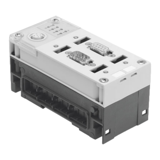
Caution The CPX bus node includes electrostatically sensitive com- ponents for Interbus. Do not touch any contacts. • Observe the handling specifications for electrostatically • sensitive devices. They will help you avoid damage to the electronics. Festo P.BE-CPX-FB6-EN en 1207c... - Page 20 CPX-spe- cific LEDs Fieldbus connec- tion OUT (contin- ued, 9-pin sub-D socket) Fieldbus connec- tion IN (incoming, 9-pin sub-D plug) Service interface for handheld, etc. Fig. 1/1: Connection and display components on the CPX bus node Festo P.BE-CPX-FB6-EN en 1207c...
- Page 21 T10. 2. Pull the bus node carefully and without tilting away from the contact rails of the interlinking block. Bus node Interlinking block Contact rails Screws Fig. 1/2: Dismantling / mounting the bus node Festo P.BE-CPX-FB6-EN en 1207c...
- Page 22 2. Only tighten the screws by hand. Place the screws so that the self-cutting threads can be used. Tighten the screws with a Torx screwdriver size T10 with torque 0.9 ... 1.1 Nm. Festo P.BE-CPX-FB6-EN en 1207c...
-
Page 23: Settings Of The Dil Switches On The Bus Node
3. Set the DIL switches as described on the following pages. 4. Mount the fieldbus plugs or the cover again, as required. Tighten the mounting screws at first by hand and then with 0.4 Nm. Festo P.BE-CPX-FB6-EN en 1207c... - Page 24 FEC/CEC is in- tegrated into the CPX terminal. Tab. 1/1: Setting the bus node operating mode Note The setting of the operating mode with the DIL switch has priority over all other settings. Festo P.BE-CPX-FB6-EN en 1207c...
- Page 25 Activating the PCP channel An additional 16 internal I/Os are assigned with the activated PCP channel. The PCP channel serves mainly for parametrisa- tion and for reading system and diagnostic data out of the CPX terminal. Festo P.BE-CPX-FB6-EN en 1207c...
- Page 26 (see also section 3.3.4). In this way, you can, for example, suppress unnecessary error messages during the commissioning phase. The setting of the DIL switch has precedence over the para- metrisation of defined settings. 1-10 Festo P.BE-CPX-FB6-EN en 1207c...
- Page 27 Set 500 kBd. Not all devices support 2 MBd. Reserved DIL switch The switch element 1 of the dual DIL switch 3 is reserved for future extensions. Reserved DIL switch Setting DIL switch 3 Reserved 3.1: OFF (default) Tab. 1/5: Reserved DIL switch 1-11 Festo P.BE-CPX-FB6-EN en 1207c...
- Page 28 (Open Load) is ignored. Report broken cable error mes- 3.2: ON sage (Open Load) Power OFF/ON is necessary after the DIL switch is changed during operation. Changes by means of parameterisation are immediately effective. Tab. 1/6: Diagnostic function 1-12 Festo P.BE-CPX-FB6-EN en 1207c...
-
Page 29: Installation
Reserved 8 I/O bytes 4.1: ON for communication of the bus node 4.2: ON with the CPX-FEC or CPX-CEC Tab. 1/7: Setting the diagnostics mode or the number of I/O bytes 1-13 Festo P.BE-CPX-FB6-EN en 1207c... -
Page 30: Connecting The Fieldbus
The CPX terminal with bus node FB6 is a remote bus station on the Interbus. Dependent on the modules used, it behaves on the remote bus like a bus terminal with integrated I/Os and must be addressed correspondingly. 1-14 Festo P.BE-CPX-FB6-EN en 1207c... - Page 31 24 VDC Interbus master: PC or PLC with interface CPX terminal: Only electric I/O modules CPX terminal: CPA valves and electric I/O modules Further Interbus stations Fig. 1/4: Remote bus system structure with CPX terminals 1-15 Festo P.BE-CPX-FB6-EN en 1207c...
- Page 32 There is 9-pin sub-D plug (incoming remote bus) as well as a 9-pin sub-D socket (continued remote bus) on the bus node for connecting the CPX terminal to the fieldbus. These connections are used for the supply line and the con- tinuation of the fieldbus line. 1-16 Festo P.BE-CPX-FB6-EN en 1207c...
-
Page 33: Pin Allocation Of The Fieldbus Interface
The CPX terminal contains the protocol chip SUPI3-OPC This ensures automatic detection of additional connected Interbus stations. There is therefore no need for a bridge between pin 5 and pin 9. Tab. 1/8: Pin allocation of bus connection 1-17 Festo P.BE-CPX-FB6-EN en 1207c... -
Page 34: Connecting The Fieldbus
1. Installation 1.3.3 Connecting the fieldbus Note Observe that only the plugs from Festo guarantee compli- ance with protection class IP 65/IP 67. If the continued bus interface is not connected: Seal the continued bus interface with the supplied cover. - Page 35 CPX-FB6 (shown at reduced size) Fig. 1/5: Fieldbus plug from Festo, type FBS-SUB-9-GS-IB-B and FBS-SUB-9-BU-IB-B Note The clamp strap in the sub-D plugs is connected internally to the metal housing of the socket or plug.
- Page 36 1. DO 2. /DO 3. DI 4. /DI 5. GND Housing/thread: screening Protective cap if connection unused. Fieldbus continued (out) Fieldbus incoming (in) Tab. 1/9: Pin allocation of the fieldbus interface with M12 connection block 1-20 Festo P.BE-CPX-FB6-EN en 1207c...
-
Page 37: Fieldbus Baud Rate And Fieldbus Length
1. Installation Fieldbus cable If the IP 65/IP 67 plugs from Festo are used, a cable outer diameter of 7-10 mm is permissible. The following cable is appropriate for use corresponding to the remote bus specific- ations: Cable selection Order no. Phoenix 3 x 2 x 0.22 mm... -
Page 38: Fibre-Optic Cable Connection For Interbus
Interbus stations. The Interbus interface of the bus node is appropriate for the Phoenix Contact Interbus/FOC converter Optosub Plus (pro- tection class IP 20) and thus supports control of network components for fibre-optic cables. 1-22 Festo P.BE-CPX-FB6-EN en 1207c... -
Page 39: Selection Of The Power Supply Unit
The current consumption of a CPX terminal depends on the number and type of integrated modules and components. Observe the information on power supply as well as on the earthing measures to be carried out in the CPX system de- scription. 1-23 Festo P.BE-CPX-FB6-EN en 1207c... - Page 40 A, B, C, D: Note:Coupling (plug socket NECU-G78G4-C2) is marked with “1, 2, 3, 4”. Allocation: D=1, C=2, B=3, A=4. Other couplings can deviate from this. Tab. 1/10: Pin allocation for system power supply, additional power supply and valve power supply 1-24 Festo P.BE-CPX-FB6-EN en 1207c...
-
Page 41: Commissioning
Commissioning Chapter 2 Commissioning Festo P.BE-CPX-FB6-EN en 1207c... - Page 42 ..........2-55 Festo P.BE-CPX-FB6-EN en 1207c...
-
Page 43: Commissioning
I/O modules can be found in the description for the CPX I/O modules (P.BE-CPX-EA-..) or CPX- analogue I/O modules (P.BE-CPX-AX-..). Instructions on commissioning the pneumatic components can be found in the corresponding description of pneumatics. Festo P.BE-CPX-FB6-EN en 1207c... -
Page 44: Configuration And Addressing
– If the PCP channel is configured, an additional 16 input addresses and 16 output addresses are occupied. – The maximum possible extension of the CPX terminal is limited to 96 inputs and outputs. The I/Os will be assigned automatically within the CPX ter- minal. Festo P.BE-CPX-FB6-EN en 1207c... - Page 45 Tab. 2/1: Number of available inputs and outputs The I/Os will be assigned automatically within the CPX ter- minal. The address assignment within the individual modules can be found in the corresponding description for the respective module. Festo P.BE-CPX-FB6-EN en 1207c...
- Page 46 Module indicators on the handheld; in the case of I/O modules these are shown in the inspection window. The status bits or the I/O diagnostics interface is activated by a DIL switch (see section 1.2). Tab. 2/2: Overview of indicators and addresses of electric modules (part 1) Festo P.BE-CPX-FB6-EN en 1207c...
- Page 47 CEC controller 8 I Additional modules in preparation. Module indicators on the handheld; in the case of I/O modules these are shown in the inspection window. Tab. 2/3: Overview of indicators and addresses of electric modules (part 2) Festo P.BE-CPX-FB6-EN en 1207c...
- Page 48 MPA2, 4 outputs assigned, independent of how many valves the pneumatic module is equipped with. Additional information on MPA pneumatic modules can be found in the description for the CPX I/O modules (P.BE-CPX- EA-..) and the corresponding description of pneumatics. Festo P.BE-CPX-FB6-EN en 1207c...
- Page 49 24 O – 1...32 solenoid coils 32 O Additional interfaces in preparation Module indicator in the Handheld Setting with DIL switches in the pneumatics interface (see description, CPX I/O modules). Tab. 2/4: Overview of pneumatics interfaces Festo P.BE-CPX-FB6-EN en 1207c...
- Page 50 MPA2 pneumatics module (type 32, VMPA2-FB-EMG-D2-4 MPA2G-D – 33) with galvanic isolation with diagnostic function D2 Additional modules in preparation Module indicator in the Handheld 8 bits are always assigned Tab. 2/5: Overview of pneumatics modules MPA-S and MPA-F 2-10 Festo P.BE-CPX-FB6-EN en 1207c...
- Page 51 DIL switch 3.2 at ON. A dia- gnostic message is also issued if an unmounted solenoid coil is addressed. All errors are registered by the CPX terminal with CPX-FB6 as common error messages (“peripheral errors”) (see description for the CPX-FB6).
- Page 52 Tab. 2/7: Overview of pneumatics modules MPA-L The complete address space including the I/Os for the dia- gnostics always includes an equal number of inputs and out- puts. Tip: Copy the following table for further calculations. 2-12 Festo P.BE-CPX-FB6-EN en 1207c...
- Page 53 15.Sum total of inputs/outputs to be configured Total of 1 to 14: = ∑ _____ I = ∑ _____ O 8 bit addresses are always assigned (4 remain unused). Tab. 2/8: Ascertaining the number of inputs and outputs 2-13 Festo P.BE-CPX-FB6-EN en 1207c...
-
Page 54: Address Assignment Of The Cpx Terminal
Note If two addresses are assigned for one valve position, the assignment applies: – less significant address: pilot solenoid coil 14 – higher-value address: pilot solenoid coil 12 2-14 Festo P.BE-CPX-FB6-EN en 1207c... - Page 55 (byte n) is mapped on inputs or outputs 8 ... 15, byte n+1 on the inputs or outputs 0 ... 7. This assignment applies also for the bytes of the I/O dia- gnostics interface. 2-15 Festo P.BE-CPX-FB6-EN en 1207c...
- Page 56 The address assignment within the pneumatics modules can be found in the description for the valve terminal pneumatics. The address assignment within the CP interface can be found in the description for the CPX-CP interface. 2-16 Festo P.BE-CPX-FB6-EN en 1207c...
- Page 57 – 8 I bits, 0 O bits (status bits) or trical interlinking, does not occupy any – 16 I/O bits (I/O diagnostics I/Os) interface) MPA pneumatics module (8 outputs) Fig. 2/1: Identification of the modules in the examples 2-17 Festo P.BE-CPX-FB6-EN en 1207c...
- Page 58 OB 22 OB 25 OB 24 Standard mode: IB = input byte; OB = output byte; status bits or I/O diagnostic interface optional Fig. 2/2: Example 1 – byte assignment in Siemens and Standard modes 2-18 Festo P.BE-CPX-FB6-EN en 1207c...
- Page 59 2. Commissioning Address assignment in Siemens mode 8DI 8DO 8DI 8DO 4DO Address assignment in Standard mode Status bits or I/O diagnostic interface optional Fig. 2/3: Example 1 – address assignment in Siemens and Standard modes 2-19 Festo P.BE-CPX-FB6-EN en 1207c...
- Page 60 OB 22 OB 25 OB 24 Standard mode: IB = input byte; OB = output byte; status bits or I/O diagnostic interface optional Fig. 2/4: Example 2 – byte assignment in Siemens and Standard modes 2-20 Festo P.BE-CPX-FB6-EN en 1207c...
- Page 61 OB 22 OB 25 OB 24 Standard mode: IB = input byte; OB = output byte; status bits or I/O diagnostic interface optional Fig. 2/5: Example 3 – byte assignment in Siemens and Standard modes 2-21 Festo P.BE-CPX-FB6-EN en 1207c...
- Page 62 OB 24 OB 27 OB 26 Standard mode: IB = input byte; OB = output byte; status bits or I/O diagnostic interface optional Fig. 2/6: Example 4 – byte assignment in Siemens and Standard modes 2-22 Festo P.BE-CPX-FB6-EN en 1207c...
- Page 63 OB 24 OB 27 OB 26 Standard mode: IB = input byte; OB = output byte; status bits or I/O diagnostic interface optional Fig. 2/7: Example 5 – byte assignment in Siemens and Standard modes 2-23 Festo P.BE-CPX-FB6-EN en 1207c...
-
Page 64: Address Assignment After Extension/Conversion
– The configured addresses of the pneumatics interface are modified. Note If the configuration is modified, the addresses of the status bits as well as those of the I/O diagnostics interface will also be shifted! 2-24 Festo P.BE-CPX-FB6-EN en 1207c... - Page 65 OB 25 OB 24 OB 27 OB 26 Standard mode: IB = input byte; OB = output byte; status bits or I/O diagnostic interface optional Fig. 2/8: Byte assignment of a CPX terminal after extension/conversion 2-25 Festo P.BE-CPX-FB6-EN en 1207c...
- Page 66 2. Commissioning Address assignment in Siemens mode 8DI 8DO 8DI 8DO 4DO 16 O Address assignment in Standard mode Status bits or I/O diagnostic interface optional Fig. 2/9: Address assignment of a CPX terminal after extension/conversion 2-26 Festo P.BE-CPX-FB6-EN en 1207c...
-
Page 67: Bus Configuration And Addressing
Configuration of the CPX terminal demands a very accurate procedure, as different configuration specifications are some- times necessary for each station on the Interbus, due to the modular structure. Note here the specifications in the sec- tions which follow. 2-27 Festo P.BE-CPX-FB6-EN en 1207c... -
Page 68: Switching On The Power Supply
Or switch on the power supply in the following sequence: 1. First switch on the power supply for all fieldbus stations. 2. Then switch on the power supply for the controller. 2-28 Festo P.BE-CPX-FB6-EN en 1207c... -
Page 69: Bus Configuration With The Cmd Software
Observe that software packages are often updated, so modifications to the software may not yet be taken into account in this description. The examples used here for the screen displays have been taken from CMD software version 4.50. 2-29 Festo P.BE-CPX-FB6-EN en 1207c... - Page 70 1. Click on the interface module with the right-hand mouse key. 2. Select the command “Einfügen mit ID-Code ...” (Insert with ident. code ...) in the context menu.. Fig. 2/10: Inserting bus stations with ident. code 2-30 Festo P.BE-CPX-FB6-EN en 1207c...
- Page 71 3. Enter the ident. code and the size of the process data channel. Information on this can be found on the following page. 4. Select the entry “Fernbusteilnehmer” (Fieldbus station) under “Teilnehmerart” (Station type) for the CPX terminal. 5. Accept these entries with OK. 2-31 Festo P.BE-CPX-FB6-EN en 1207c...
- Page 72 – If the number of input bits differs from the number of output bits, the greater number is in each case decisive for entry of the process data channel bits. – The 16 bits of the PCP channel do not count as process data channel bits. 2-32 Festo P.BE-CPX-FB6-EN en 1207c...
- Page 73 6. Enter 128 bytes each for “Senden” (Send) and “Empfan- gen” (Receive) under “Telegrammlängen” (Telegram lengths). 7. Activate the check boxes “Read”, “Write” and “Get OD” (object dictionary) under “Unterstützte Parameter- kanal-Dienste” (Support parameter channel services). 2-33 Festo P.BE-CPX-FB6-EN en 1207c...
- Page 74 9. Interface type: Universal is preset. This setting can be accepted. Alternat- ively, with the button “Schnittstellentyp” (Interface type), you can open a dialogue window in which you can set the type “Fernbus” (remote bus). 2-34 Festo P.BE-CPX-FB6-EN en 1207c...
- Page 75 – in the internet under www.festo.com (Download Area – Fieldbus Utilities), – on the Utility CD from Festo (in preparation). Copy the files “CPX-01.ico” und “CPX-PCP.ico” into the • CMD directory \PICTURE\. Actuate the button “Auswählen ...” (Select ...) in the •...
- Page 76 Select one of the files “CPX-01.ico” (CPX terminal • without PCP channel) or “CPX-PCP.ico” (CPX terminal with PCP channel). Fig. 2/15: Dialogue window “Darstellung” (Representation) for selecting an icon Accept your selection with OK. • 2-36 Festo P.BE-CPX-FB6-EN en 1207c...
- Page 77 2. Commissioning When all entries have been made, the CPX terminal will be integrated into your bus structure as follows (example): Fig. 2/16: Example – inserted CPX terminal 2-37 Festo P.BE-CPX-FB6-EN en 1207c...
-
Page 78: Bus Configuration Without Cmd Software
16 inputs and outputs. – Observe that the maximum number of process data bits is reduced by 16 inputs and outputs when the PCP channel is activated. – Assign logical IN and OUT addresses to each station. 2-38 Festo P.BE-CPX-FB6-EN en 1207c... -
Page 79: Process Data Entry Via The Cmd Software
1. Insert a CPX terminal into your bus structure (necessary steps see section 2.1.6 “Bus configuration with the CMD software”). 2. Select the command “Prozessdaten” (Process data) in the context menu of the CPX terminal. Fig. 2/17: Open the dialogue window “Prozessdaten” (Process data) 2-39 Festo P.BE-CPX-FB6-EN en 1207c... - Page 80 In this way you can adapt the I/Os of the CPX termin- al to the PLC used. The following diagram shows the byte-by- byte assignment for a Siemens S7: Fig. 2/18: Entering process data – example for “Siemens mode” 2-40 Festo P.BE-CPX-FB6-EN en 1207c...
- Page 81 The following dialogue window shows the entries required for interchanging the assignment of the high byte and the low byte (example: byte swap for “standard mode”). Fig. 2/19: Modification of the I/O assignment (byte swap) – example for “standard mode” 2-41 Festo P.BE-CPX-FB6-EN en 1207c...
-
Page 82: Configuration In The Remote Controller Operating Mode
(see section 1.2, Tab. 1/1). operating mode 2. Set 8 I/O bytes with DIL switch ( see section 1.2, Tab. 1/7). The bus node is thus configured as remote controller. 2-42 Festo P.BE-CPX-FB6-EN en 1207c... -
Page 83: Parametrisation
CPX system description. Which module parameters are available for the various mod- ules can be found in the description for the respective mod- ule (e.g. description for CPX I/O modules (P.BE-CPX-EA-..)). 2-43 Festo P.BE-CPX-FB6-EN en 1207c... - Page 84 CPX terminal is re- placed during servicing. In these cases, check before re- placement to see which settings are required and carry out these settings. 2-44 Festo P.BE-CPX-FB6-EN en 1207c...
-
Page 85: Parametrisation Concepts
PLC user program. Note Without the PCP channel, parametrisation is only possible with the handheld. Further information on the PCP channel can be found in the appendix. 2-45 Festo P.BE-CPX-FB6-EN en 1207c... - Page 86 In this are saved in the user functions way, parametrisation can program. Remote be undertaken flexibly via a maintenance is there- PLC user program. fore possible Tab. 2/1: Parametrisation concepts – part 1 2-46 Festo P.BE-CPX-FB6-EN en 1207c...
- Page 87 Recommendation: Use the parametrisation via the PLC user program. You will then achieve a high degree of reliability and flexibility. Further instructions on the procedure for parametrisation can be found in the sections which follow. 2-47 Festo P.BE-CPX-FB6-EN en 1207c...
- Page 88 If the system parameter “System start” has the setting “Systemstart mit gespeicherter Parametrierung und gespeichertem CPX-Ausbau” (System start with saved parametrisation and saved CPX expansion), modified para- meter settings in the CPX terminal will become valid imme- diately after power on. 2-48 Festo P.BE-CPX-FB6-EN en 1207c...
-
Page 89: Device Parametrisation With The Cmd Software
CPX terminal. The individual parametrisation undertaken can be saved within the CMD software. If a parameter file (*.dsc) with instructions is available, it can be loaded in the CMD software. 2-49 Festo P.BE-CPX-FB6-EN en 1207c... -
Page 90: Parametrisation With Cmd User Functions
The user function is started by the user program The boot attribute for the user function is set The function is carried out when the module starts up. Fig. 2/21: “Anwenderfunktion” (User function) – boot attribute is set 2-50 Festo P.BE-CPX-FB6-EN en 1207c... - Page 91 2. Commissioning Fig. 2/22: “Anwenderfunktion – Parameter bearbeiten” (User function – process parameters) 2-51 Festo P.BE-CPX-FB6-EN en 1207c...
- Page 92 You can start and monitor a user function from your user pro- gram. The parameter values are transferred to the user func- tion, e.g. via Interbus process data words. Fig. 2/23: User function – parameters are transferred via variables (e.g. process data words). 2-52 Festo P.BE-CPX-FB6-EN en 1207c...
-
Page 93: Parametrisation With The Plc User Program
:=DB21 // CR number of the PCP slave TOGGLE :=M120.5 // Second bit ONLY_INITIATE:=TRUE :=M120.2 // Result bit FC_BUSY :=M120.3 // Activate function ACTIVATE_BITS:=MB103 INITIALIZE :=M120.4 STATUS :=MW104 Fig. 2/24: Program example (SIEMENS STEP 7) 2-53 Festo P.BE-CPX-FB6-EN en 1207c... -
Page 94: Commissioning The Cpx Terminal On The Interbus
“CMD device parametrisation” or with the handheld. The M/TR LED signals communication via the PCP chan- • nel. You can then ascertain whether parametrisation via the PCP channel has taken place, e.g. in the start-up phase. 2-54 Festo P.BE-CPX-FB6-EN en 1207c... -
Page 95: Fail Safe
CPU and the Interbus interface module will be synchronised. This is to prevent 0-signals from being incorrectly transmitted via the Interbus. Otherwise, useful Fail Safe treatment or pro- gramming would not be possible. 2-55 Festo P.BE-CPX-FB6-EN en 1207c... - Page 96 2. Commissioning 2-56 Festo P.BE-CPX-FB6-EN en 1207c...
-
Page 97: Diagnostics And Error Handling
Diagnostics and error handling Chapter 3 Diagnostics and error handling Festo P.BE-CPX-FB6-EN en 1207c... - Page 98 ..........3-20 Festo P.BE-CPX-FB6-EN en 1207c...
-
Page 99: Diagnostics And Error Handling
Information on diagnosing the pneumatic interface and the I/O modules can be found in the manual for the CPX I/O mod- ules (P.BE-CPX-EA-..) Instructions on diagnosing the pneumatics can be found in the relevant pneumatics description. Festo P.BE-CPX-FB6-EN en 1207c... -
Page 100: Summary Of Diagnostics Options
PLC user program Diagnostics via Diagnostic information can Fast “on-site” error detec- Description for the the handheld be shown on the handheld tion Handheld in a convenient and menu- driven manner. Tab. 3/1: Diagnostics options Festo P.BE-CPX-FB6-EN en 1207c... - Page 101 (see section 3.3.4). Note Observe that the diagnostic information shown can de- pend on the DIL switch settings on the bus node as well as on the parametrisation of the CPX terminal. Festo P.BE-CPX-FB6-EN en 1207c...
-
Page 102: Diagnostics Via Leds
– M (yellow) *) Interbus-specific LEDs: – UL (green) – RC (green) – BA (green) – RD (yellow) – TR (yellow) *) The LED M/TR is assigned twice Fig. 3/1: LEDs on the CPX bus node CPX-FB6 Festo P.BE-CPX-FB6-EN en 1207c... -
Page 103: Normal Operating Status
LEDs do not light up. LED display Operating status All green LEDs light up: Standard – UL – RC – BA – PS – PL Red and yellow LEDs do not light up: – SF – RD – M/TR Festo P.BE-CPX-FB6-EN en 1207c... -
Page 104: Cpx-Specific Leds
LED (green) Process Status Significance / error handling No error. Load voltage ap- None plied LED illuminated Load voltage at the system Eliminate undervoltage supply or additional power supply outside the toler- LED flashes ance range Festo P.BE-CPX-FB6-EN en 1207c... - Page 105 The System Failure LED flashes dependent on the applicable error class. Error class 1 (simple error): 1 * flashing, pause time Error class 2 (error): 2 * flashing, pause time Error class 3 (serious error): 3 * flashing, pause time Festo P.BE-CPX-FB6-EN en 1207c...
- Page 106 The LED M/TR is intended for several functions (see also un- der Interbus-specific LEDs). The status which is shown takes place in the following sequence: 1. Force active 2. Parameters saved remanently 3. PCP communication 3-10 Festo P.BE-CPX-FB6-EN en 1207c...
-
Page 107: Interbus-Specific Leds
• the Interbus. Reset interface module. • Interface module initiates Acknowledge error. LED flashes • ID cycles. Start data transmission. No data transmission on Interface module not in “run” status. the Interbus. LED not illuminated 3-11 Festo P.BE-CPX-FB6-EN en 1207c... - Page 108 PCP chan- nel. CPX terminal does not At present there is no communication send/receive data via the PCP channel LED not illuminated The LED M/TR is intended for several functions (see also un- der CPX-specific LEDs). 3-12 Festo P.BE-CPX-FB6-EN en 1207c...
-
Page 109: Diagnostics Via Interbus
CPX terminal will set them to “logical zero”. The addresses of the status bits in the address space depend, like all inputs/outputs, on the Interbus interface and on the control system used (see section 2.1.2). 3-13 Festo P.BE-CPX-FB6-EN en 1207c... - Page 110 If required, errors can be uniquely defined via the I/O dia- gnostics interface. Further instructions on the function and content of the status bits can be found in the CPX system description. 3-14 Festo P.BE-CPX-FB6-EN en 1207c...
-
Page 111: I/O Diagnostics Interface
Inter- bus module and on the control system used (see section 2.1.2). Instructions on diagnostics with the I/O diagnostics interface can be found in the CPX system description. 3-15 Festo P.BE-CPX-FB6-EN en 1207c... -
Page 112: Diagnostics Via The Pcp Channel
A.3. Information on the available diagnostic information and its function numbers can be found in the CPX system manual. 3-16 Festo P.BE-CPX-FB6-EN en 1207c... - Page 113 – Number of entries in the dia- gnostic memory – Operating mode Diagnostic memory data – Long-term memory (max. 40 entries) – Detail diagnostics + relative time stamp per error event Tab. 3/3: Diagnostics data 3-17 Festo P.BE-CPX-FB6-EN en 1207c...
-
Page 114: Peripheral Faults (Pf)
– short circuit or overload at digital outputs. – further specific error messages of the CPX terminal. Additional information on error messages of the CPX terminal can be found in the CPX system description. 3-18 Festo P.BE-CPX-FB6-EN en 1207c... - Page 115 The system is not stopped due to peripheral faults. You can define the reaction to peripheral faults in the user program. A peripheral fault is also acknowledged in the user program. 3-19 Festo P.BE-CPX-FB6-EN en 1207c...
-
Page 116: Error Handling
PLC stop or fieldbus interruption or malfunction: – Single-solenoid valves move to the normal position – Double-solenoid valves remain in the current position. – Mid-position valves go into mid-position (pressurized, exhausted or closed, depending on valve type). 3-20 Festo P.BE-CPX-FB6-EN en 1207c... -
Page 117: A. Technical Appendix
Technical appendix Appendix A Technical appendix Festo P.BE-CPX-FB6-EN en 1207c... - Page 118 ..........Technical data bus node type CPX-FB6 .
-
Page 119: Technical Appendix
A. Technical appendix Technical data bus node type CPX-FB6 General General technical data See CPX system description: – Description P.BE-CPX-SYS-... Protection class according to EN 60 529, CPX- IP 65/IP 67 FB6 completely mounted, plug connector, like accessories, plugged in or equipped with pro-... - Page 120 LI-YCY, 3 x 2 x 0.25 mm , 120 pF/m max. cable capacity Cable length at 500 kBd – between two remote bus slaves Max. 400 m – of the complete system up to 12.8 km Festo P.BE-CPX-FB6-EN en 1207c...
-
Page 121: Accessories
A. Technical appendix Accessories The following table provides an overview of necessary and useful accessories for the bus node CPX-FB6. Accessories Type Designation Description FBS-SUB-9-BU-IB-B STECKER,SUB9-D Socket for fieldbus connection in- coming, 9-pin Sub-D, IP 65/IP 67 FBS-SUB-9-GS-IB-B STECKER,SUB9-D Plug for fieldbus connection contin-... -
Page 122: Access To Parameters And Data Via The Pcp Channel
The description and mode of operation of the individual para- meters and data can be found in the CPX system description. Note Bytes and bits not listed are reserved for future exten- sions. Festo P.BE-CPX-FB6-EN en 1207c... - Page 123 – Per data cycle, 8 bits of parameter data and 8 bits of ad- ministrative data are transmitted – “Breaking up” and “Putting together” the parameter data takes place via the Interbus protocol chip (SUPI). Festo P.BE-CPX-FB6-EN en 1207c...
-
Page 124: Parameters In The Operating Mode Remote I/O
– Bit 4: short circuit at valves (SCV) Fail safe (bit 0, 1) 4402 74F5 – byte 2 (behaviour with communication errors) Force mode (bit 2, 3) 4402 74F5 – byte 2 (enable/block force) System start (bit 6) 4402 74F5 – byte 2 Festo P.BE-CPX-FB6-EN en 1207c... -
Page 125: A.4.2 Module Parameters
(internal errors) 5532 75E5 – byte 0 5596 75F5 – byte 0 5660 7605 – byte 0 5724 7615 – byte 0 5788 7625 – byte 0 5852 7635 – byte 0 5916 7645 – byte 0 Festo P.BE-CPX-FB6-EN en 1207c... - Page 126 5535 75E5 – byte 3 5599 75F5 – byte 3 5663 7605 – byte 3 5727 7615 – byte 3 5789 7625 – byte 3 5853 7635 – byte 3 5917 7645 – byte 3 A-10 Festo P.BE-CPX-FB6-EN en 1207c...
- Page 127 5538 75E5 – byte 6 5602 75F5 – byte 6 5666 7605 – byte 6 5730 7615 – byte 6 5794 7625 – byte 6 5858 7635 – byte 6 5922 7645 – byte 6 A-11 Festo P.BE-CPX-FB6-EN en 1207c...
- Page 128 – Bit 7: Parametrisation errors 5730 ... 5731 7615 – byte 6, 7 5794 ... 5795 7625 – byte 6, 7 5858 ... 5859 7635 – byte 6, 7 5922 ... 5923 7645 – byte 6, 7 A-12 Festo P.BE-CPX-FB6-EN en 1207c...
- Page 129 5541 75E5 – byte 9 5605 75F5 – byte 9 5669 7605 – byte 9 5733 7615 – byte 9 5797 7625 – byte 9 5861 7635 – byte 9 5925 7645 – byte 9 A-13 Festo P.BE-CPX-FB6-EN en 1207c...
- Page 130 5734 ... 5741 7615 – byte 10 ... 17 5797 ... 5805 7625 – byte 10 ... 17 5861 ... 5869 7635 – byte 10 ... 17 5925 ... 5933 7645 – byte 10 ... 17 A-14 Festo P.BE-CPX-FB6-EN en 1207c...
- Page 131 – 760A – byte 0 ... 3 – 761A – byte 0 ... 3 – 762A – byte 0 ... 3 – 763A – byte 0 ... 3 – 764A – byte 0 ... 3 A-15 Festo P.BE-CPX-FB6-EN en 1207c...
- Page 132 – 760C – byte 0 ... 3 – 761C – byte 0 ... 3 – 762C – byte 0 ... 3 – 763C – byte 0 ... 3 – 764C – byte 0 ... 3 A-16 Festo P.BE-CPX-FB6-EN en 1207c...
- Page 133 – 75EE – byte 0 – 75FE – byte 0 – 760E – byte 0 – 761E – byte 0 – 762D – byte 0 – 763D – byte 0 – 764D – byte 0 A-17 Festo P.BE-CPX-FB6-EN en 1207c...
-
Page 134: A.4.3 Diagnostic Memory Parameters
– byte 2 Overflow (bit 0) 3483 74F8 – byte 3 Status (bit 1) Diagnostic memory data (bit 0 ... 7) 3488 ... 3887 see following table (10 bytes per diagnostic entry, max. 40 entries) A-18 Festo P.BE-CPX-FB6-EN en 1207c... - Page 135 3848 ... 3857 751D – byte 0 ... 9 3858 ... 3867 751E – byte 0 ... 9 3868 ... 3877 751F – byte 0 ... 9 3878 ... 3887 7520 – byte 0 ... 9 A-19 Festo P.BE-CPX-FB6-EN en 1207c...
-
Page 136: System Diagnostics Data
– Bit 6: wire break – Bit 7: other error Module number and diagnostic status (bit 0 ... 6) 1937 74F7 – byte 1 Error number (bit 0 ... 7) 1938 74F7 – byte 2 A-20 Festo P.BE-CPX-FB6-EN en 1207c... -
Page 137: A.4.6 Module Diagnostics Data
– byte 0 ... 3 2064 ... 2067 2068 ... 2071 7622 – byte 0 ... 3 2072 ... 2075 7632 – byte 0 ... 3 2076 ... 2079 7642 – byte 0 ... 3 A-21 Festo P.BE-CPX-FB6-EN en 1207c... -
Page 138: A.4.7 System Data
224, 237 7600 – byte 0, 13 240, 253 7610 – byte 0, 13 256, 269 7620 – byte 0, 13 272, 285 7630 – byte 0, 13 288, 301 7640 – byte 0, 13 A-22 Festo P.BE-CPX-FB6-EN en 1207c... - Page 139 840 ... 843 7611 – byte 0 ... 3 844 ... 847 7621 – byte 0 ... 3 848 ... 851 7631 – byte 0 ... 3 852 ... 855 7641 – byte 0 ... 3 A-23 Festo P.BE-CPX-FB6-EN en 1207c...
-
Page 140: A.4.9 Length Of The Pcp Data Objects
7535 Module parameter, m_paramw_n each (4828 + n*64) 7545 module n 64 bytes ... (4837 + n*64) PCP name shown via the service “Get_OD” Access: r = read, w = write n = module number A-24 Festo P.BE-CPX-FB6-EN en 1207c... - Page 141 754D module n 64 bytes 753E Force state inputs, m_frcste_n each 754E module n 64 bytes PCP name shown via the service “Get_OD” Access: r = read, w = write n = module number A-25 Festo P.BE-CPX-FB6-EN en 1207c...
- Page 142 A. Technical appendix A-26 Festo P.BE-CPX-FB6-EN en 1207c...
- Page 143 Index Appendix B Index Festo P.BE-CPX-FB6-EN en 1207c...
-
Page 144: B. Index
............Festo P.BE-CPX-FB6-EN en 1207c... - Page 145 2-7, 2-42 Diagnostics mode ....... 1-13 Festo P.BE-CPX-FB6-EN en 1207c...
- Page 146 ......... . . Festo P.BE-CPX-FB6-EN en 1207c...
- Page 147 ........1-20 Festo P.BE-CPX-FB6-EN en 1207c...
- Page 148 ......1-24 VTSA pneumatics (ISO) ......Festo P.BE-CPX-FB6-EN en 1207c...
Need help?
Do you have a question about the CPX-FB6 and is the answer not in the manual?
Questions and answers