Festo CPX-FB14 Electronic Manual
Cpx terminal
Hide thumbs
Also See for CPX-FB14:
- Description (182 pages) ,
- Electronic manual (154 pages) ,
- Brief description (74 pages)

Related Manuals for Festo CPX-FB14


Summary of Contents for Festo CPX-FB14
- Page 1 CPX terminal Electronics manual CPX field bus node Type CPX−FB14 Field bus protocol: CANopen Manual 526 410 en 0308a [674 172]...
- Page 3 ....... . . 526 410 E (Festo AG & Co. KG, D 73726 Esslingen, Federal Republic of Germany, 2003) Internet: http://www.festo.com...
- Page 4 Contents and general instructions Festo P.BE−CPX−FB14−E N en 0308a...
-
Page 5: Table Of Contents
........1−25 1.3.5 Connecting with field bus plugs from Festo ....1−26 1.3.6... - Page 6 ........3−21 Festo P.BE−CPX−FB14−E N en 0308a...
- Page 7 ............B−1 Festo P.BE−CPX−FB14−E N en 0308a...
-
Page 8: Designated Use
The maximum values specified for pressures, tempera tures, electrical data, torques, etc. must not be exceeded. Observe also the standards specified in the relevant chapters, as well as national and local laws and technical regulations. Festo P.BE−CPX−FB14−E N en 0308a... -
Page 9: Target Group
This manual is intended exclusively for technicians trained in control and automation technology who have experience in installing, commissioning, programming and diagnosing sla ves on the CANopen field bus. Service Please consult your local Festo repair service if you have any technical problems. Festo P.BE−CPX−FB14−E N en 0308a... -
Page 10: Notes On The Use Of This Manual
EDS file as from 29.07.2003 Support of MPA pneumatics 1) Software status (SW) see type plate This manual contains specific information on installing, confi guring, parametrizing, commissioning, programming and diagnosing with the CPX field bus node for CANopen. VIII Festo P.BE−CPX−FB14−E N en 0308a... -
Page 11: Important User Instructions
This means that failure to observe this instruction may result in damage to property. The following pictogram marks passages in the text which describe activities with electrostatically sensitive compo nents. Electrostatically sensitive components may be damaged if they are not handled correctly. Festo P.BE−CPX−FB14−E N en 0308a... - Page 12 Accessories: Information on necessary or sensible accessories for the Fe sto product. Environment: Information on environment−friendly use of Festo products. Text markings The bullet indicates activities which may be carried out in · any order. 1. Figures denote activities which must be carried out in the numerical order specified.
- Page 13 CPA pneumatics" sioning CPA pneumatics (type 12) Type P.BE−CPA−... Valve terminals with Instructions on fitting, installing and commis Midi/Maxi pneumatics" sioning Midi/Maxi pneumatics (type 03) type P.BE−Midi/ Maxi−03−... Tab. 0/1: Manuals on the CPX terminal Festo P.BE−CPX−FB14−E N en 0308a...
- Page 14 The pneumatic interface is the interface between the modular electrical peripherals and the pneumatics. PLC/IPC Programmable logic controller/industrial PC Status bits Internal inputs which supply coded common diagnostic messages. Hexadecimal numbers are marked by a subscript h". Tab. 0/2: Product−specific terms and abbreviations Festo P.BE−CPX−FB14−E N en 0308a...
-
Page 15: Installation
Installation Chapter 1 1−1 Festo P.BE−CPX−FB14−E N en 0308a... - Page 16 ........1−25 1.3.5 Connecting with field bus plugs from Festo ....1−26 1.3.6...
- Page 17 CPX pneumatic interface and CPX I/O modules (P.BE−CPX−EA−..). Instructions on installing the pneumatic components can be found in the relevant pneumatics manual (see Tab. 0/1). 1−3 Festo P.BE−CPX−FB14−E N en 0308a...
-
Page 18: General Instructions On Installation
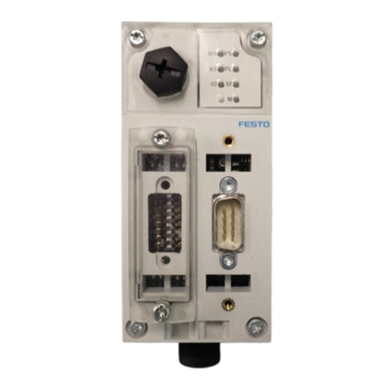
Observe the regulations for handling electrostatically · sensitive components. In this way you will avoid damage to the electronics. Information on fitting the CPX terminal can be found in the CPX system manual (P.BE−CPX−SYS−..). 1−4 Festo P.BE−CPX−FB14−E N en 0308a... - Page 19 CPX field bus node for CANopen: Bus status LEDs and CPX−specific LEDs Service interface for handheld Field bus connection (9−pin sub−D plug) Transparent cover for DIL switches Fig. 1/1: Connecting and display elements on the CPX field bus node 1−5 Festo P.BE−CPX−FB14−E N en 0308a...
- Page 20 2. Pull the field bus node carefully and without tilting away from the contact rails of the manifold sub−base. Field bus node CPX−FB14 Manifold sub−base Contact rails Torx T10 screws Fig. 1/2: Dismantling/fitting the field bus node 1−6 Festo P.BE−CPX−FB14−E N en 0308a...
- Page 21 2. Tighten the screws at first only by hand. Insert the screws so that the self−boring threads can be used. Tighten the screws with a Torx screwdriver size T10 with 0.9 ... 1.1 Nm. 1−7 Festo P.BE−CPX−FB14−E N en 0308a...
-
Page 22: Setting The Dil Switches On The Field Bus Node
Fitting 1. Place the cover carefully onto the node. Please note Make sure that the seal is seated correctly. · 2. Tighten the fastening screws at first by hand and then with 0.4 Nm. 1−8 Festo P.BE−CPX−FB14−E N en 0308a... -
Page 23: Setting The Dil Switches
7. With operating mode Remote I/O: Set the CPX diagnostic mode (DIL switch 5). With operating mode Remote Controller: Set the required number of logical I/Os of the CPX−FB14 (DIL switch 5). 8. Fit the cover (see section 1.2.1). 1−9 Festo P.BE−CPX−FB14−E N en 0308a... - Page 24 Station number DIL switch 4: Baud rate DIL switch 5: CPX diagnostic mode or number of logical I/Os with Remote Controller" Fig. 1/3: DIL switches in the field bus node (further information on below) 1−10 Festo P.BE−CPX−FB14−E N en 0308a...
- Page 25 An FEC integrated in the CPX terminal takes over control of the I/Os. This op erating mode is only useful if there is an FEC in the CPX terminal. Tab. 1/1: Setting the operating mode 1−11 Festo P.BE−CPX−FB14−E N en 0308a...
- Page 26 In this way, you can e.g. suppress unnecessary fault messages during the commis sioning phase. The setting of the DIL switch has precedence over the parametrizing of defined settings. No Emergency Message is transmitted with the fault filtering. 1−12 Festo P.BE−CPX−FB14−E N en 0308a...
- Page 27 Example: Set station num Example: Set station num ber: 05 ber: 38 2 + 4 + 32 = 1 + 4 = Tab. 1/3: Examples of set station numbers (binary coded) 1−13 Festo P.BE−CPX−FB14−E N en 0308a...
- Page 28 1. Installation On the following pages you will find an overview of the station number settings. 1−14 Festo P.BE−CPX−FB14−E N en 0308a...
- Page 29 1. Installation tion tion not permitted Tab. 1/4: Setting station numbers 1−31: Position of the DIL switch elements 1−15 Festo P.BE−CPX−FB14−E N en 0308a...
- Page 30 1. Installation tion tion Tab. 1/5: Setting station numbers 32−63: Position of the DIL switch elements 1−16 Festo P.BE−CPX−FB14−E N en 0308a...
- Page 31 1. Installation tion tion Tab. 1/6: Setting station numbers 64−95: Position of the DIL switch elements 1−17 Festo P.BE−CPX−FB14−E N en 0308a...
- Page 32 1. Installation tion tion Tab. 1/7: Setting station numbers 96−127: Position of the DIL switch elements 1−18 Festo P.BE−CPX−FB14−E N en 0308a...
- Page 33 250 kBaud 4.1: ON 4.2: OFF 500 kBaud 4.1: OFF 4.2: ON 1000 kBaud 4.1: ON 4.2: ON Tab. 1/8: Setting the baud rate The following table shows the settings of the DIL switch. 1−19 Festo P.BE−CPX−FB14−E N en 0308a...
- Page 34 5.1: ON sions: 5.2: ON 64 I/Os (8 x 8 bits) are in tended for communication of the field bus node with the FEC. Tab. 1/9: Function of DIL switch 5 (depends on operating mode) 1−20 Festo P.BE−CPX−FB14−E N en 0308a...
-
Page 35: Connecting The Field Bus
The CANopen bus interface of the CPX terminal is sup plied with power via the field bus cable. If the Festo field bus plug is used, a cable diameter of 5−8 mm or 7−10 mm is permitted. Please note... -
Page 36: Field Bus Baud Rate And Field Bus Length
Take into account also the sum of the branch line lengths · when calculating the maximum permitted length of the field bus cable. 1−22 Festo P.BE−CPX−FB14−E N en 0308a... -
Page 37: Information On Connecting The Field Bus
The following tolerance in the bus interface supply (pin 3/pin 9 on the sub−D plug) applies to the CPX terminal: = 30.0 V = 11.0 V Recommendation: Place the power unit approximately in the centre of the bus. 1−23 Festo P.BE−CPX−FB14−E N en 0308a... - Page 38 1. Installation You can implement a T−adapter with the Festo field bus plug (see fig.). Ó Ó Ó Ó Field bus Branch line Power supply T−adapter (T−tap) Screening/shield Field bus plug with T−adapter function Fig. 1/5: Structure of the bus interface and example of connection 1−24...
-
Page 39: Field Bus Interface
There is 9−pin sub−D plug on the field bus node for connecting the CPX terminal to the field bus. This connection serves for the incoming and continuing field bus cables. You can con nect the CPX terminal with the field bus plug from Festo type FBS−SUB−9−BU−2x5POL−B. Please note Note that only the Festo field bus plug guarantees com pliance with protection class IP65. -
Page 40: Connecting With Field Bus Plugs From Festo
SUB−9−BU−2x5pol−B). You can disconnect the plug from the node without interrupting the bus cable (T−tap function). Please note The clamp strap in the Festo field bus plug is connected only capacitively internally with the metal housing of the sub−D plug. This prevents equalizing currents from flowing via the screening of the field bus cable (Fig. - Page 41 Clamp strap for screening Bus out connection Protective cap if connection is not used Field bus continuing (OUT) Field bus incoming (IN) Only connected capacitively Fig. 1/6: Field bus plug from Festo type FBS−SUB−9−BU−2x5POL−B 1−27 Festo P.BE−CPX−FB14−E N en 0308a...
-
Page 42: Further Connection Possibilities For The Field Bus With Adapters
Connect the screening/shield. · There are further possibilities of connecting the CPX terminal with adapters which can be ordered separately from Festo. M12 adapter 5−pin (protection class IP65) type: FBA−2−M12−5pol screw terminal adapter 5−pin (protection class IP20) type: FBA−1−SL−5pol 1−28... - Page 43 Use protective caps or blanking plugs to seal unused · connections. In this way you will comply with protection class IP65. Order this connection from Festo (type: FBA−2−M12−5pol). M12 adapter Pin no. 1. Screening/shield 2. 24 V DC bus (max. 4 A) 3.
- Page 44 The maximum permitted current at the terminals is 4 A. Use cables with a cross sectional area of min. 0.34 mm Order this connection from Festo (type: FBA−1−SL−5pol) to gether with the terminal strip type FBSD−KL−2x5pol. Screw terminal Pin no.
-
Page 45: Bus Termination With Terminating Resistors
(120 Ω, 0.25 W) Fig. 1/9: Bus termination with resistor in the field bus plug from Festo 1.4.1 Install a terminating resistor using the adapters. If the CPX terminal to be connected is at the end of the field bus, a terminating resistor (120 Ω, 0.25 W) must be fitted in... -
Page 46: Pin Assignment Of The Power Supply
The current requirement of a CPX terminal depends on the number and type of integrated modules and components. Note the information on power supply as well as the earthing measures to be carried out as described in the CPX system manual. 1−32 Festo P.BE−CPX−FB14−E N en 0308a... - Page 47 / 0 V 4: Earth/ground 4: Earth/ground 4: Earth/ground connection connection connection operating voltage for electronics/sensors el/sen undervoltage at outputs load voltage for valves Tab. 1/11: Pin assignment of system supply, additional supply and valve supply 1−33 Festo P.BE−CPX−FB14−E N en 0308a...
- Page 48 1. Installation 1−34 Festo P.BE−CPX−FB14−E N en 0308a...
-
Page 49: Commissioning
Commissioning Chapter 2 2−1 Festo P.BE−CPX−FB14−E N en 0308a... - Page 50 ..... 2−66 2.6.1 Faultless commissioning, normal operating status ... . . 2−67 2−2 Festo P.BE−CPX−FB14−E N en 0308a...
- Page 51 Information on commissioning the pneumatic interface and I/O modules can be found in the manual for the CPX I/O mod ules (P.BE−CPX−EA−..). Instructions on commissioning the pneumatic components can be found in the relevant pneumatics manual (see Tab. 0/1). 2−3 Festo P.BE−CPX−FB14−E N en 0308a...
-
Page 52: Commissioning On A Canopen Master
A CANopen system is configured mainly by access to the object directory of the individual slaves. The access mechanism is provided by Service Data Objects (SDOs). There are two different communication mechanisms in a CANopen system. 2−4 Festo P.BE−CPX−FB14−E N en 0308a... - Page 53 The Service Data Objects (SDO) form a point−to−point connec tion and permit access to every entry in the object directory of a node. 2−5 Festo P.BE−CPX−FB14−E N en 0308a...
-
Page 54: Configuration
8 bits in the Transmit PDO 4 (standard setting). The 16 bits of the I/O diagnostic interface must be treated like inputs and outputs. They each occupy 16 bits in the Transmit and Receive PDO 4 (standard setting). 2−6 Festo P.BE−CPX−FB14−E N en 0308a... - Page 55 Receive PDO 1 A0−A7 A8−A15 A16−A23 A24−A31 A32−A39 A40−A47 A48−A55 A56−A63 Transmit PDO 2...4 unused Receive PDO 2...4 unused Fig. 2/2: 64 logical I/Os in the PDO 1 in the operating mode Remote Controller 2−7 Festo P.BE−CPX−FB14−E N en 0308a...
-
Page 56: Configuration Examples With Cpa Pneumatics
Field bus node CPX−FB14 Multi I/O module 8−input module Analogue 2−output module 8−input module Pneumatic interface (with DIL switch set to 1...16 valve coils) 4−output module Valves/CPA pneumatics Fig. 2/3: Example terminal 1 (with CPA pneumatics) 2−8 Festo P.BE−CPX−FB14−E N en 0308a... - Page 57 B: CPX−GP−CPA−... The pneumatic interface must face, set with DIL switch be configured correctly accord to 1 ... 16 valve coils ing to the connected pneumatic components. Tab. 2/2: Configuration for example terminal 1 2−9 Festo P.BE−CPX−FB14−E N en 0308a...
- Page 58 Field bus node CPX−FB14 Multi I/O module 8−input module Pneumatic interface for MPA pneumatics (only mechanical/ Multi I/O module electrical connection) 4−output module Valves/MPA pneumatic modules Fig. 2/4: Example terminal 2 (with MPA pneumatics) 2−10 Festo P.BE−CPX−FB14−E N en 0308a...
- Page 59 (8DA) electrical isolation of the voltage supplies. MPA pneumatic module VI: CPX−type32: 1−8V.. MPA pneumatic module without (VI: CPX−type32: 1−8V..) (8DA) electrical isolation of the voltage supplies. Tab. 2/3: Configuration for example terminal 2 2−11 Festo P.BE−CPX−FB14−E N en 0308a...
-
Page 60: Addressing Examples
If the telegram received is shorter than the necessary telegram length, a fault message will be output. If the telegram received is longer, the part correspon ding to the necessary length will be processed. 2−12 Festo P.BE−CPX−FB14−E N en 0308a... - Page 61 Ó Ó Ó R− PDO1 A0−A7 A8−A15 A16−A23 A24−A31 R− PDO2 Fig. 2/6: Assignment of the PDOs on a CPX terminal with digital and analogue I/O mod ules and CPA pneumatics (standard assignment without mapping) 2−13 Festo P.BE−CPX−FB14−E N en 0308a...
- Page 62 E0−E7 E8−E15 E16−E23 4DO 8DI 8DO R− PDO1 A0−A7 A8−A15 A16−A23 A24−A31 A32−A39 Fig. 2/7: Assignment of the PDOs on a CPX terminal with digital I/O modules and MPA pneumatics (standard assignment without mapping) 2−14 Festo P.BE−CPX−FB14−E N en 0308a...
-
Page 63: Overview
4 Process Data Objects for access to digital/analogue inputs Emergency telegram for fault message to the master Node guarding / Heart beat Default setting of all identifiers as per DS 301 and the station address (predefined connection set) Variable mapping 2−15 Festo P.BE−CPX−FB14−E N en 0308a... -
Page 64: Overview Object Directory
6000, 6100 Input Array 6200, 6300 Output Array 6206/6306 Fault Mode Array for the outputs 6207/6307 Fault State Array for the outputs 64xx Analogue inputs and outputs Tab. 2/4: Implemented objects of the CPX terminal 2−16 Festo P.BE−CPX−FB14−E N en 0308a... -
Page 65: Reaction Of The Cpx Terminal When It Is Switched On
2. Commissioning 2.3.3 Reaction of the CPX terminal when it is switched on Power on Application initialization Communication initialization Pre−operational Stopped Operational Fig. 2/8: Status transitions of the CPX terminal (description see next page) 2−17 Festo P.BE−CPX−FB14−E N en 0308a... - Page 66 Maskings of the outputs are reset to default Communication parameters are reset (objects 1000 ... 1FFF) Saved parameters (2000 ... 5FFF) will not be loaded. only after the transition from Operational mode to Stopped or Pre−operational mode Tab. 2/5: Status transitions 2−18 Festo P.BE−CPX−FB14−E N en 0308a...
-
Page 67: Default Identifier Distribution
2. Commissioning 2.3.4 Default Identifier distribution The following table shows the identifier distribution: Broadcast objects Object name Object designation Value range of the COB identifier on the CPX terminal SYNC Tab. 2/6: Broadcast objects 2−19 Festo P.BE−CPX−FB14−E N en 0308a... - Page 68 ... 1407 Transmit SDO SDO1 (tx) 1409 ... 1535 Receive SDO SDO1 (rx) 1537 ... 1663 Node guarding / Guarding Heart beat 1793 ... 1919 Tab. 2/7: Peer to Peer objects of the CPX−FB14 2−20 Festo P.BE−CPX−FB14−E N en 0308a...
-
Page 69: Object Directories
00 0F 91 01 As from software status V1.10: OF = maximum amount of equipment on the CPX ter minal 1001 Error no error register register Generic / Manufacturer er ror (see chapter 3.5.1) 2−21 Festo P.BE−CPX−FB14−E N en 0308a... - Page 70 1008 Manufac Str. − FB14" Node designation turer Device Name 1009 Manufac Str. − 0601" Current hardware status turer (example) Hardware Version 100A Manufac Str. − V1.2" Current software status turer (example) Software Version 2−22 Festo P.BE−CPX−FB14−E N en 0308a...
- Page 71 00 00 00 1D Vendor ID (from CiA) Product 00 00 00 CD Product code code Revision xx xx.xx xx Version (like object 100A) number Serial num xx xx xx xx Serial number (individual for each module) 2−23 Festo P.BE−CPX−FB14−E N en 0308a...
- Page 72 2 = stopped Error codes: 23xx, 33xx Input Error With short circuit/overload at input module or failure in sensor supply 0 = pre−operational 1 = no state change 2 = stopped Error codes: 21xx, 31xx 2−24 Festo P.BE−CPX−FB14−E N en 0308a...
- Page 73 Default COB−ID + Node ID Server (rx) COB_ID 580 + Node ID Default COB−ID + Node ID Server Client (tx) U = unsigned, ro = read only, rw = read/write, Map. = Mapping possible, Attr. = Attribute 2−25 Festo P.BE−CPX−FB14−E N en 0308a...
-
Page 74: Overview Of The Pdo Structure
180 + Node ID Trans Default: Acyclic mission type Inhibit time 00 00 Transmit blocking time in puts [100 s] − − not used Event timer 00 00 Time−controlled trans mission of the inputs [ms] 2−26 Festo P.BE−CPX−FB14−E N en 0308a... - Page 75 60 00 05 08 ... Index E32 − E39 60 00 06 08 ... Index E40 − E47 60 00 07 08 ... Index E48 − E55 60 00 08 08 ... Index E56 − E63 2−27 Festo P.BE−CPX−FB14−E N en 0308a...
- Page 76 ... Inputs 56 −63 ... Inputs 64 −71 ... Inputs 72 −79 ... Inputs 80 −87 ... Inputs 88 −95 ... Inputs 96 −103 ... Inputs 104 −111 ... Inputs 112 −119 ... Inputs 120 −127 2−28 Festo P.BE−CPX−FB14−E N en 0308a...
-
Page 77: Digital Outputs (Receive Pdo 1)
... Index A48 − A55 62 00 08 08 ... Index A56 − A63 U = unsigned, ro = read only, rw = read/write, Map. = Mapping possible, Attr. = Attribute (see instruction with Fig. 2/5) 2−29 Festo P.BE−CPX−FB14−E N en 0308a... - Page 78 ... Outputs 56 −63 ... Outputs 64 −71 ... Outputs 72 −79 ... Outputs 80 −87 ... Outputs 88 −95 ... Outputs 96 −103 ... Outputs 104 −111 ... Outputs 112 −119 ... Outputs 120 −127 2−30 Festo P.BE−CPX−FB14−E N en 0308a...
- Page 79 ... Outputs 56 −63 ... Outputs 64 −71 ... Outputs 72 −79 ... Outputs 80 −87 ... Outputs 88 −95 ... Outputs 96 −103 ... Outputs 104 −111 ... Outputs 112 −119 ... Outputs 120 −127 2−31 Festo P.BE−CPX−FB14−E N en 0308a...
- Page 80 ... Outputs 72 −79 ... Outputs 80 − 87 ... Outputs 88 − 95 ... Outputs 96 − 103 ... Outputs 104 − 111 ... Outputs 112 − 119 ... Outputs 120 − 127 2−32 Festo P.BE−CPX−FB14−E N en 0308a...
- Page 81 1 = output assumes the status defined in Index 6207 Bit 0 ... 7 6207 0 = output is reset Subindex 1 Subindex 1 ... 10 Bit 0 ... 7 1 = output is set 2−33 Festo P.BE−CPX−FB14−E N en 0308a...
-
Page 82: Analogue Inputs Channel 0 − 3 (Transmit Pdo 2)
The channel number of the interrupt−triggering analogue input is entered in Object 6422. The PDO is then transmitted according to the transmission code in Object 1801 (FF , FD , FC or 0 ... F0 2−34 Festo P.BE−CPX−FB14−E N en 0308a... - Page 83 Event timer 00 00 Time−controlled trans mission of the inputs [ms] U = unsigned, ro = read only, rw = read/write, Map. = Mapping possible, Attr. = Attribute see remark on side 2−27 2−35 Festo P.BE−CPX−FB14−E N en 0308a...
- Page 84 Enable 6422 Analogue − Number of Interrupt Source Input Number Banks of Interrupt Source Banks Interrupt − Interrupt Source Bank 1 Source Bank 1 (channel 0 ... 15) is reset automatically after read access 2−36 Festo P.BE−CPX−FB14−E N en 0308a...
- Page 85 Maximum value AE 3 Bit 0: Upper limit exceeded" (as per DS 401) Bit 1: Input below lower limit" (as per DS 401) Bit 2: Input changed by more than delta" (as per DS 401) 2−37 Festo P.BE−CPX−FB14−E N en 0308a...
- Page 86 AE 1 Minimum value modification AE 2 Minimum value modification AE 3 Bit 1: Input below lower limit" (as per DS 401) Bit 2: Input changed by more than delta" (as per DS 401) 2−38 Festo P.BE−CPX−FB14−E N en 0308a...
-
Page 87: Analogue Outputs Channel 0 − 3 (Receive Pdo 2)
00 00 00 00 Pointer at Mapping Object 5 00 00 00 00 Pointer at Mapping Object 6 00 00 00 00 Pointer at Mapping Object 7 00 00 00 00 Pointer at Mapping Object 8 2−39 Festo P.BE−CPX−FB14−E N en 0308a... - Page 88 Integer 32 bit Error Value AA 0 Error Value AA 1 Error Value AA 2 Error Value AA 3 U = unsigned, ro = read only, rw = read/write, Map. = Mapping possible, Attr. = Attribute 2−40 Festo P.BE−CPX−FB14−E N en 0308a...
-
Page 89: Analogue Inputs Channel 4 −15 (Transmit Pdo 3)
Event timer 00 00 Time−controlled trans mission of the inputs [ms] U = unsigned, ro = read only, rw = read/write, Map. = Mapping possible, Attr. = Attribute see remark on page 2−27 2−41 Festo P.BE−CPX−FB14−E N en 0308a... - Page 90 − Anzahl der Interrupt Source Input Number Banks (see PDO 2) of Interrupt Source Banks Interrupt − Interrupt Source Bank 1 Source Bank 1 (channel 1 ... 16) is reset automatically after read access 2−42 Festo P.BE−CPX−FB14−E N en 0308a...
- Page 91 AE 5 AE 15 6424 Analogue − 0 ... 10 Number of analogue inputs Input Interrupt Upper Limit Integer Analogue Maximum value AE 4 Input Input Maximum value AE 5 Maximum value AE 15 2−43 Festo P.BE−CPX−FB14−E N en 0308a...
- Page 92 Minimum value AE 15 6426 Analogue − 0 ... 10 Number of analogue inputs Input Interrupt Delta Unsigned Analogue Minimum value modification Input AE 4 Minimum value modification AE 5 Minimum value modification AE 15 2−44 Festo P.BE−CPX−FB14−E N en 0308a...
-
Page 93: Analogue Outputs Channel 4 −15 (Receive Pdo 3)
00 00 00 00 Pointer at Mapping Object 5 00 00 00 00 Pointer at Mapping Object 6 00 00 00 00 Pointer at Mapping Object 7 00 00 00 00 Pointer at Mapping Object 8 2−45 Festo P.BE−CPX−FB14−E N en 0308a... - Page 94 Number of analogue Output Error channels Integer 32 bit Integer 32 bit 00 00 00 00 Error Value AA 4 00 00 00 00 Error Value AA 5 00 00 00 00 Error Value AA 15 2−46 Festo P.BE−CPX−FB14−E N en 0308a...
-
Page 95: Status Bits And I/O Diagnostic Interface (Pdo 4)
Default COB−ID of the inputs Node ID Transmission Default: Acyclic type Inhibit time 00 00 Transmit blocking time in puts [100 s] − − not used Event timer 00 00 Time−controlled trans mission of the inputs [ms] 2−47 Festo P.BE−CPX−FB14−E N en 0308a... - Page 96 00 00 00 00 Pointer at Mapping Object 8 6100 Read Input 0 ... 8 Number of 16−input groups 16 bit 16 bit Depending on configuration: status bits or I/O diagnostic interface 2 ... 8 − reserved 2−48 Festo P.BE−CPX−FB14−E N en 0308a...
- Page 97 00 00 00 00 Pointer at Mapping Object 5 00 00 00 00 Pointer at Mapping Object 6 00 00 00 00 Pointer at Mapping Object 7 00 00 00 00 Pointer at Mapping Object 8 2−49 Festo P.BE−CPX−FB14−E N en 0308a...
- Page 98 2. Commissioning Index Designation Type Attr Values Explanation (hex) index (hex) 6300 Write Output − 0 ... 8 Number of 16−output 16 bit groups If configured: I/O diagnostic interface 2 ... 8 − reserved 2−50 Festo P.BE−CPX−FB14−E N en 0308a...
- Page 99 00 00 ... Outputs 48 − 63 00 00 ... Outputs 64 − 79 00 00 ... Outputs 80 − 95 00 00 ... Outputs 96 − 111 00 00 ... Outputs 112 − 127 2−51 Festo P.BE−CPX−FB14−E N en 0308a...
-
Page 100: Manufacturer Specific Profile
System diagnostic data System diagnostic data Details see Tab 2/11 Details see Tab. 2/11. 2210 Module diagnostic data − Details see Tab. 2/12. Tab. 2/8: Overview of the indices of the Manufacturer Specific Profile Area 2−52 Festo P.BE−CPX−FB14−E N en 0308a... - Page 101 Index 6206, 6207, 6306, 0001 6307 Monitoring Monitoring the CPX terminal: 0002 the CPX ter Bit 0 ... 3: short circuit/over minal load/undervol tage Bit 4 ... 7: reserved Tab. 2/9: System data 2−53 Festo P.BE−CPX−FB14−E N en 0308a...
- Page 102 1 ... Number of entries 784 + Module Module serial number serial num serial num ber module Module serial num ber module All details: See appendix in CPX system manual Tab. 2/10: Module data 2−54 Festo P.BE−CPX−FB14−E N en 0308a...
- Page 103 + xx + xx reserved reserved Diagnostic 00 ... FF I/O channel/channel number module 1 00 ... FF Fault number reserved reserved All details: See appendix in CPX system manual Tab. 2/12: Module diagnostic data 2−55 Festo P.BE−CPX−FB14−E N en 0308a...
- Page 104 3. Entry power on) power on) 00...FF Module code 00...2F 00...2F Module position Module position 00...FF Channel number 40. Entry 00...FF Fault number (oldest 00...FF Following channels saved fault) Tab. 2/13: Diagnostic memory data 2−56 Festo P.BE−CPX−FB14−E N en 0308a...
- Page 105 Bit 4, 5: not implemented Bit 6, 7: System start 4 ... 8 reserved − reserved − Tab. 2/14: System parameters Detailed information on parameters and data can be found in the CPX system manual. 2−57 Festo P.BE−CPX−FB14−E N en 0308a...
- Page 106 63 Data format analogue module 1 values 2412, 0 ... Parameters See CPX system manual 0 ... 63 appendix B Module 2 ... Depends on module, see CPX system manual Tab. 2/15: Module parameters 2−58 Festo P.BE−CPX−FB14−E N en 0308a...
-
Page 107: Overview Of Mapping Objects
1 ... 16 Default Mapping E0 ... E15 Read input E112 ... E127 113 ... 128 6200 Write output Status of the outputs 1 ... 8 Default Mapping A0...A7 Write output A120 ... A127 121... 128 2−59 Festo P.BE−CPX−FB14−E N en 0308a... - Page 108 Default Mapping AE 0 Read ana AE 15 logue input 16 6411 Write ana Analogue output channels logue output 1 Default Mapping AA 0 Write ana AA 15 logue output Tab. 2/16: Overview of mapping objects 2−60 Festo P.BE−CPX−FB14−E N en 0308a...
-
Page 109: Forcen
Force mode E120 ... E127 5007 Force mode 0 ... 10 Number of entries − 8 bit digital 8−bit digital Force value E0 ... E7 inputs Force value E8 ... E15 Force value E120 ... E127 2−61 Festo P.BE−CPX−FB14−E N en 0308a... - Page 110 0 ... 10 Number of entries − analogue in analogue in Force value channel 0 (AE0) puts Force value channel 1 (AE1) Force value channel 15 (AE15) Values: 0 = Disable, 1 = Enable 2−62 Festo P.BE−CPX−FB14−E N en 0308a...
- Page 111 Force mode A112 ... A127 5307 Force value 0 ... 8 Number of entries − 16 bit digital 16−bit digital Force value A0 ... A15 outputs Force value A16 ... A31 Force value A112 ... A127 2−63 Festo P.BE−CPX−FB14−E N en 0308a...
- Page 112 Force value 0 ... 10 Number of entries − analogue analogue Force mode channel 0 outputs (AA0) Force mode channel 1 (AA1) Force mode channel 15 (AA15) Values: 0 = Disable, 1 = Enable 2−64 Festo P.BE−CPX−FB14−E N en 0308a...
-
Page 113: Parametrizing
CPX I/O modules (P.BE−CPX−EA−..). 2.5.1 Parametrizing when switching on Parametrizing is Network loaded into the node by the master. Parametrizing is distributed to the modules by the node. Fig. 2/9: Sequence of start parametrizing 2−65 Festo P.BE−CPX−FB14−E N en 0308a... -
Page 114: Parametrizing With The Handheld
(applies to the complete module). Modification of the signal lengthening time to 50 ms: The signal will be registered reliably by the controller. (here activated only for the input channel of the 2nd. sensor). 2−66 Festo P.BE−CPX−FB14−E N en 0308a... -
Page 115: Commissioning Of The Cpx Terminal In The System
Providing the safety concept of your machine/system per mits, commission the CPX terminal with both operating volt ages (pins 1 and 2) but without compressed air. You can then test the CPX terminal without triggering undesired reac tions. 2−67 Festo P.BE−CPX−FB14−E N en 0308a... -
Page 116: Faultless Commissioning, Normal Operating Status
In the normal operating status the LEDs on the field bus node light up as follows: LED display Operating status These LEDs light up normal green: Red and yellow LEDs do not light up: 2−68 Festo P.BE−CPX−FB14−E N en 0308a... -
Page 117: Diagnosis
Diagnosis Chapter 3 3−1 Festo P.BE−CPX−FB14−E N en 0308a... - Page 118 ........3−21 3−2 Festo P.BE−CPX−FB14−E N en 0308a...
-
Page 119: Diagnosis
Information on diagnosing the pneumatic interface and the I/O modules can be found in the manual for the CPX I/O mod ules (P.BE−CPX−EA−..). Instructions on diagnosing the pneumatic components can be found in the relevant pneumatics manual (see Tab. 0/1). 3−3 Festo P.BE−CPX−FB14−E N en 0308a... -
Page 120: Overview Of Diagnostic Possibilities
Tab. 3/1: Diagnostic possibilities Please note Note that the diagnostic information shown can depend on the settings (see section 1.2.2) as well as on the parame trizing (see section 2.5) of the CPX terminal. 3−4 Festo P.BE−CPX−FB14−E N en 0308a... -
Page 121: Diagnosis Via Leds
M (yellow) CANopen−specific LEDs (green/red): MS (module status) NS (network status) I/O (I/O status) Fig. 3/1: LEDs of the CPX node In the following the LEDs are represented in their various states: lights up; flashes; 3−5 Festo P.BE−CPX−FB14−E N en 0308a... -
Page 122: Normal Operating Status
In the normal operating status the LEDs on the field bus node light up as follows: LED display Operating status These LEDs light up normal green: Red and yellow LEDs do not light up: Tab. 3/2: LEDs with normal operating status 3−6 Festo P.BE−CPX−FB14−E N en 0308a... -
Page 123: Fault Displays Of The Cpx−Specific Leds Ps, Pl, Sf, M
PL (Power Load) power load supply (outputs/valves) LED (green) Sequence Status Meaning/fault treatment No fault Load voltage ap None plied LED lights up Load voltage at the system Eliminate undervoltage supply or additional supply outside the tolerance LED flashes range 3−7 Festo P.BE−CPX−FB14−E N en 0308a... - Page 124 The system fault LED flashes depending on the class of fault which has occurred. Fault class 1 (simple fault): flash once, pause Fault class 2 (fault): flash twice, pause Fault class 3 (serious fault): flash three times, pause Tab. 3/3: Fault diagnosis with the LED SF 3−8 Festo P.BE−CPX−FB14−E N en 0308a...
- Page 125 In these cases, check be manently; external fore replacement to see which set parametrizing is blocked. tings are required and carry out these settings. Tab. 3/4: Messages of the LED M 3−9 Festo P.BE−CPX−FB14−E N en 0308a...
-
Page 126: Fault Displays Of The Canopen−Specific Leds Ms, Ns, Io
LED flashes 2 Hz fast green Non−permitted station Set correct station number. · number 0 set If there is still a problem: servicing is required LED flashes Hardware fault servicing is required LED lights up 3−10 Festo P.BE−CPX−FB14−E N en 0308a... - Page 127 LED flashes green Failure of the 24 V Check and restore power supply · CAN−receiver supply LED flashes Bus OFF Check the bus: Cables, plug · connectors, signal transmission (fault counter overrun) LED lights up 3−11 Festo P.BE−CPX−FB14−E N en 0308a...
- Page 128 LED flashes ture on a module Communication fault" 1. Clarify reason for Time out Node guard or Heart beat 2. Set CPX terminal to Operational expired (system assumes mode LED lights up Pre−operational mode) 3−12 Festo P.BE−CPX−FB14−E N en 0308a...
-
Page 129: Diagnosis Via Status Bits
Fault at output Fault at input Fault on analogue module/ function module Undervoltage Type of fault Short circuit/overload Wire fracture Other faults Tab. 3/5: Status bits of the CPX FB14 (optional) 3−13 Festo P.BE−CPX−FB14−E N en 0308a... -
Page 130: Diagnosis Via The I/O Diagnostic Interface
In order to use the I/O diagnostic interface, you must acti vate it with the DIL switch on the field bus node (see sec tion 1.2.2). Information on the I/O diagnostic interface can be found in the CPX system manual P.BE−CPX−SYS−.. . 3−14 Festo P.BE−CPX−FB14−E N en 0308a... -
Page 131: Diagnosis Via Canopen
MS, NS or IO Fig. 3/2: Sequence of fault processing in the CPX terminal Information on the reaction of the inputs and outputs in the event of a fault can also be found in the sections 2.4. 3−15 Festo P.BE−CPX−FB14−E N en 0308a... -
Page 132: The Emergency Message
Status bits, CPX module no., Error Code The Pre−defined Error Field serves as fault memory for the last 10 faults. Previous faults will each be shifted by one position (see chapter2.4, Index 1003, Subindices 1 ...A) 3−16 Festo P.BE−CPX−FB14−E N en 0308a... - Page 133 Communication fault (bus voltage not applied) CAN Overrun CAN in Error Passive mode Fault with Node guard or Heart beat CAN recovered from Bus OFF invalid PDO received Tab. 3/6: Composition of the error code as per DS 401 3−17 Festo P.BE−CPX−FB14−E N en 0308a...
- Page 134 Error register (Index 1001 with bit assignment as per DS 301/401) Further diagnostic information is provided by the CPX ter minal in bytes 3 ... 6 of the Emergency Object (Manufacturer status register, Index 1002). 3−18 Festo P.BE−CPX−FB14−E N en 0308a...
- Page 135 Module type on which a fault has occurred Fault at output Fault at input Fault on analogue module/ function module Undervoltage Type of fault Short circuit/overload Wire fracture Other faults Tab. 3/8: Byte 0 of the Manufacturer Status Register (status bits) 3−19 Festo P.BE−CPX−FB14−E N en 0308a...
- Page 136 Index Index 1002 (Manufacturer Status Register) 1001 Meaning Explanation 0 ... 7 CPX fault number CPX fault number (see section 3.5.2) Tab. 3/10: Byte 2 of the Manufacturer Status Register (CPX fault number) 3−20 Festo P.BE−CPX−FB14−E N en 0308a...
-
Page 137: Cpx Fault Numbers
Tab. 3/11: Byte 7 of the Emergency Object 3.5.2 CPX fault numbers The table on the following pages shows the CPX fault numbers. Detailed information can be found in the CPX system manual in the chapter Diagnosis and fault treatment". 3−21 Festo P.BE−CPX−FB14−E N en 0308a... - Page 138 Wire fracture at valve (open load) reserved Module/channel failed Module code not permitted or incorrect module reserved Number of I/O points exceeded Internal CPX communication faulty Tab. 3/12: CPX fault numbers (part 1) 3−22 Festo P.BE−CPX−FB14−E N en 0308a...
- Page 139 Bus off Bus Power lost 48 ... 127 reserved 128 ... 199 Fault in CPX structure (fault number is fault in formation for service personnel) Tab. 3/13: CPX fault numbers (part 2) 3−23 Festo P.BE−CPX−FB14−E N en 0308a...
- Page 140 Fault number Fault type Fault in parameter transfer to module Invalid station number (node) Bus protocol chip: not ready reserved 204 ... 205 see manual for relevant module Tab. 3/14: CPX fault numbers (part 3) 3−24 Festo P.BE−CPX−FB14−E N en 0308a...
- Page 141 Technical appendix Appendix A A−1 Festo P.BE−CPX−FB14−E N en 0308a...
-
Page 142: A. Technical Appendix
....... . . A−6 Example: Parametrizing with the program CANsetter" ....A−7 A−2 Festo P.BE−CPX−FB14−E N en 0308a... -
Page 143: Technical Appendix
24 V DC (protected against incorrect polarity, external fuse required) Tolerance 11 ... 30 V Current consumption max. 30 mA Electrical isolation Bus interface opto−decoupled Technical specifications of the pneumatics can be found in the pneumatics manual (see Tab. 0/1). A−3 Festo P.BE−CPX−FB14−E N en 0308a... -
Page 144: Examples: Communication Sequence
Receive−PDO must be sent by the master. In the example only output 0 is set, any outputs already set will be reset. (all values in hex) 201 : 01 00 PLC/PC/IPC Fig. A/2: Example 2, set output 0 of the CPX terminal A−4 Festo P.BE−CPX−FB14−E N en 0308a... -
Page 145: Example 3: Start Node Guard" Monitoring
Node guard response PLC/PC/IPC 701 : (all values in hex) Fig. A/3: Example 3, start Node guard" monitoring ( Remote request) A−5 Festo P.BE−CPX−FB14−E N en 0308a... -
Page 146: Example 4: Load Objects
00 10 00 00 00 00 PLC/PC/IPC 581 : 00 10 91 01 02 00 (all values in hex) Fig. A/4: Example 4, Index 1000 , read Subindex 0 (device type: device profile, device extension) A−6 Festo P.BE−CPX−FB14−E N en 0308a... -
Page 147: Example 5: Write Objects
(not relevant) 601 : 0C 10 04 7F 00 00 PLC/PC/IPC 581 : 0C 10 00 00 00 00 (all values in hex) Fig. A/5: Example 5: Index 100C , Subindex 0 written (Guard Time) A−7 Festo P.BE−CPX−FB14−E N en 0308a... -
Page 148: Example: Parametrizing With The Program Cansetter
The program CANsetter" is available from Vector Informatik GmbH. You can parametrize the CPX terminal easily with CAN setter. Further information can be found in Internet under www.vector−informatik.com. Fig. A/6: Example of parametrizing with CANsetter A−8 Festo P.BE−CPX−FB14−E N en 0308a... - Page 149 Index Appendix B B−1 Festo P.BE−CPX−FB14−E N en 0308a...
-
Page 150: B. Index
............B−1 B−2 Festo P.BE−CPX−FB14−E N en 0308a... - Page 151 ....... . 1−32 CPX diagnostic mode ......1−20 B−3 Festo P.BE−CPX−FB14−E N en 0308a...
- Page 152 ......... 2−60 Heart beat ..... . 2−18 , 2−23 , 3−17 , 3−18 B−4 Festo P.BE−CPX−FB14−E N en 0308a...
- Page 153 ........2−29 B−5 Festo P.BE−CPX−FB14−E N en 0308a...
- Page 154 ........2−49 B−6 Festo P.BE−CPX−FB14−E N en 0308a...
- Page 155 ........1−33 B−7 Festo P.BE−CPX−FB14−E N en 0308a...
Need help?
Do you have a question about the CPX-FB14 and is the answer not in the manual?
Questions and answers