Table of Contents
Advertisement
Quick Links
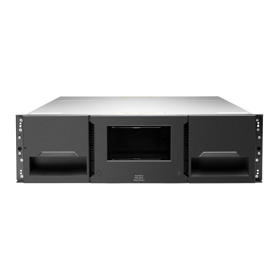
HPE StoreEver MSL3040 Tape Libraries
User and Service Guide
Abstract
This guide provides information on installing, configuring, upgrading, and troubleshooting the
library. This guide is intended for system administrators and other users who need physical
and functional knowledge of the library.
Part Number: Q6Q62-00029b
Published: February 2018
Edition: 3
Advertisement
Table of Contents

Related Manuals for HP StoreEver MSL3040


Summary of Contents for HP StoreEver MSL3040
- Page 1 HPE StoreEver MSL3040 Tape Libraries User and Service Guide Abstract This guide provides information on installing, configuring, upgrading, and troubleshooting the library. This guide is intended for system administrators and other users who need physical and functional knowledge of the library.
- Page 2 © Copyright 2017, 2018 Hewlett Packard Enterprise Development LP Notices The information contained herein is subject to change without notice. The only warranties for Hewlett Packard Enterprise products and services are set forth in the express warranty statements accompanying such products and services. Nothing herein should be construed as constituting an additional warranty. Hewlett Packard Enterprise shall not be liable for technical or editorial errors or omissions contained herein.
-
Page 3: Table Of Contents
Contents Overview....................9 Front panel............................9 Rear panel..........................10 USB ports............................ 11 Tape drive back panels........................11 LTO-6 Fibre Channel tape drive back panel..............11 LTO-6 SAS tape drive back panel..................12 LTO-7 and LTO-8 Fibre Channel tape drive back panel...........12 LTO-7 and LTO-8 SAS tape drive back panel..............12 MSL3040 power supply LEDs.....................13 Module and tape drive numbering.................... - Page 4 Initiating the configuration wizard....................43 Verifying the host connections....................43 Configuring the FC interface....................... 43 Labeling tape cartridges......................44 Loading tape cartridges......................44 Verifying the installation......................44 Downloading product firmware..................45 Configuring additional features....................45 Operating the library................47 Library user interfaces........................ 47 The MSL3040 RMI......................47 The MSL3040 OCP......................47 MSL3040 OCP menu........................48 Logging in to the library.......................50...
- Page 5 Downloading log and trace files..................101 Managing library firmware....................102 Managing drive firmware from the RMI................103 Downloading a tape drive support ticket................ 103 Downloading a library support ticket................104 Rebooting the library...................... 104 Rebooting a tape drive....................104 Clearing drive reservations.................... 104 Controlling the UID LED....................105 Moving the robotic assembly to the base module............
- Page 6 Preparing to remove the controller board...............132 Removing a module controller board................133 Installing the new controller board................. 133 Completing the module controller replacement..............134 Verifying the base or expansion module controller installation........134 Replacing the drive power board....................135 Powering off the library....................135 Preparing to remove the drive power board..............135 Removing the library or expansion controller and drive power boards......
- Page 7 Detection problems after installing a SAS drive................167 Operation problems........................169 The library does not power on..................170 No messages on the OCP..................... 171 Cartridge stuck in drive....................171 Cartridge stuck in storage slot..................172 Cartridge incompatible with drive................... 172 Cannot read or write to data cartridge................172 The library reports an obstruction in a storage slot or does not see a data cartridge..
- Page 8 Documentation feedback......................196 Event codes..................197 Error events..........................197 Warning events......................... 215 Configuration change events....................232 Informational events........................235 Technical specifications..............238 Physical specifications......................238 Environmental specifications....................238 Electrical specifications......................239 Regulatory specifications......................239 Regulatory compliance identification numbers................. 240 Default and restore defaults settings..................240 Contents...
-
Page 9: Overview
WARNING: Only personnel with technical and product safety training (referred to as users in this document) may have access to or operate the HPE StoreEver MSL3040 Tape Library. • Read all documentation and procedures before installing or operating the library. -
Page 10: Rear Panel
Base module only Navigation button – Right Right magazine and mailslot access Enter button Base module only Right magazine release button Navigation button – Down Base module only USB port Base module only Base module only Back/Return button Base module only OCP LEDs, left to right •... -
Page 11: Usb Ports
Module alignment mechanism Module controller LEDs, from top to bottom: • Health status, green • Error, amber • Unit identifier (UID), blue Product serial number tag location USB ports The library has two USB ports — one on the OCP and one on the back panel. You can update firmware, save or restore configuration settings, or download support tickets with a USB thumb drive in either USB port. -
Page 12: Lto-6 Sas Tape Drive Back Panel
LTO-6 SAS tape drive back panel 1. Tape drive Ethernet port 2. SAS port A 3. SAS port B 4. Tape drive power LED, green LTO-7 and LTO-8 Fibre Channel tape drive back panel 1. Tape drive Ethernet port 2. FC port A 3. -
Page 13: Msl3040 Power Supply Leds
1. Tape drive Ethernet port 2. SAS port A 3. SAS port B 4. Tape drive power LED, green MSL3040 power supply LEDs LED color Description Green Module is powered on. White AC power is connected. Module and tape drive numbering Modules and tape drives are numbered from the bottom of the library up, starting with the number one. -
Page 14: Encryption
Figure 1: Storage slot and mailslot numbering The robot cannot access the lowest row of storage slots in the library. If the library only has a base module, the library will have 32 storage slots. Each expansion module adds 40 storage slots. Figure 2: The lowest row of storage slots in the library are inaccessible to the robot. -
Page 15: Hpe Storeever 1/8 G2 Tape Autoloader And Msl Tape Libraries Encryption Kit
The tape drives can read encrypted data from and write encrypted data to some earlier generation media. The following table shows backward compatibility for encrypted data. Table 1: Read and write compatibility for encrypted data Media LTO-6 drive LTO-7 drive LTO-8 drive LTO-4 media (encrypted Read only with... -
Page 16: Kmip Key Manager Integration
Table 2: KMIP licenses Part number License description Q8K98A HPE StoreEver MSL3040 KMIP Key Manager LTU Q8K98AAE HPE StoreEver MSL3040 KMIP Key Manager E-LTU Use the Expert Partition Wizard to configure the use of a key manager. The library supports the use of one key manager type at a time. -
Page 17: Guidelines For Using And Maintaining Data Cartridges
Guidelines for using and maintaining data cartridges CAUTION: Do not degauss LTO data cartridges! The data cartridges are prerecorded with a magnetic servo signal, which is required to use the cartridges with LTO tape drives. Keep magnetically charged objects away from data cartridges. To ensure the longest possible life for your data cartridges, follow these guidelines: •... -
Page 18: Read And Write Compatibility
Write-protect switch in the unlocked position Write-protect switch in the locked position Write-protect switch Barcode label Directional arrow. Insert the cartridge into the magazine with the arrow pointing into the storage slot. 2. Slide the switch to the right to write-protect the cartridge. An indicator, such as a red mark or small padlock, indicates that the cartridge is write-protected. -
Page 19: Supported Media
LTO-6 drive LTO-7 drive LTO-8 drive LTO-7 Type M media — unencrypted Incompatible Incompatible Read/Write LTO-7 Type M media — encrypted Incompatible Incompatible Read/Write with encryption key LTO-8 media — unencrypted Incompatible Incompatible Read/Write LTO-8 media — encrypted Incompatible Incompatible Read/Write with encryption key Supported media... -
Page 20: Hpe Command View For Tape Libraries
Table 8: LTO-7 Type M media for LTO-8 drives Cartridge type Part number HPE LTO-7 Ultrium Type M 22.5 TB RW Custom Labeled Data Cartridges (20 Q2078ML pack) HPE LTO-7 Ultrium Type M 22.5 TB RW Non-Custom Labeled Data Cartridges Q2078MN (20 pack) Table 9: LTO-8 data cartridges... -
Page 21: Hpe Data Verification
For more information about TapeAssure Advanced, see: http://www.hpe.com/storage/tapeassure NOTE: HPE StoreEver TapeAssure Advanced Software is licensed by tape library; one license is required for each tape library HPE Data Verification HPE StoreEver Data Verification Software proactively validates and scans, nondisruptively, the quality of data stored on LTO tape cartridges. -
Page 22: Path Failover Features
1. Tape drive Ethernet ports are connected to the private network for the Data Verification feature. 2. Library DIAG port is connected to the private network for the Data Verification feature. 3. Library Ethernet port is connected to the site LAN to provide user access through the RMI. 3. - Page 23 HPE StoreEver High Availability MSL3040 LTO-6 Data Path Failover E-LTU Table 11: Failover licenses for LTO-7 and later generation drives Part number License name Q8L00A HPE StoreEver MSL3040 LTO-7+ Path Failover LTU Q8L00AAE HPE StoreEver MSL3040 LTO-7+ Path Failover E-LTU Path failover configuration and status Control path and data path failover are configured and enabled with the expert partition wizard.
-
Page 24: Secure Manager
Secure Manager is a licensed feature and can only be enabled after the license has been added to the library. Table 12: Secure Manager licenses Part number Description Q8K99A HPE StoreEver MSL3040 Secure Manager LTU Q8K99AAE HPE StoreEver MSL3040 Secure Manager E-LTU Secure Manager... -
Page 25: Installing The Library
Installing the library WARNING: Each library module weighs 20 kg (44 lb) without media or tape drives and at least 35 kg (77 lb) with media (40 cartridges) and three tape drives. When moving the library, to reduce the risk of personal injury or damage to the device: •... -
Page 26: Location Requirements
• FC connection information • SAS connection information 4. Library partition guidelines Location requirements The library must be installed in a supported rack on the provided rack shelves. Select a location with access to the host server that meets the location requirements. Table 13: Location requirements Criteria Definition... -
Page 27: Fc Connection Information
If the library will be sharing the rack with other equipment, place heavy devices, such as disk arrays, in the bottom of the rack to reduce the chance of the rack tipping. FC connection information Connect the FC tape drive directly to the server with an HBA or indirectly through a SAN with an FC switch. - Page 28 controllers do not support tape devices. To verify the specifications of your HBA or find a list of compatible HBAs, see the DAPR compatibility matrix: http://www.hpe.com/storage/DAPRcompatibility CAUTION: Do not connect the library to a SAS RAID controller unless the DAPR compatibility matrix shows that the controller is qualified with the library.
-
Page 29: Library Partition Guidelines
The tape drive has a mini-SAS connector. The connector is keyed in location 4, which is the standard location for end devices. If you use a cable other than the one recommended for use with the product, verify that it is keyed in location 4. CAUTION: Mini SAS connectors are keyed. -
Page 30: Preparing The Host
Use the Expert Partition Wizard to configure partitions that will have different resources or to adjust resource assignments for existing partitions or partitions created with the Basic Partition Wizard. CAUTION: The library goes off line while partitions are being configured. Ensure that all host operations are idle before running a partition wizard. - Page 31 The robotics is protected during shipment by a foam insert that must be removed before installation. IMPORTANT: To avoid personal injury or damage to the module, always support the bottom of the module where the rack shelf contacts the module. Do not touch internal mechanical or electrical components while moving the module.
-
Page 32: Installing The Shelves In The Rack
5. If you are installing a library with an expansion module above the base module, keep the top cover with the base module until the cover is installed on the top expansion module. 6. Save the packaging materials for future use. Installing the shelves in the rack Each module is supported by a pair of shelves and is secured to the rack with captive fasteners. - Page 33 Orientation for a square-hole rack. The face with square inserts is installed into the square rack holes. Orientation for a round-hole rack. The face with the round inserts is placed against the rack posts. b. Align the adapter block in the bottom 2U of the 3U volume that the module will occupy, as shown in the illustration.
-
Page 34: Installing The Base Module In The Rack
5. From the front of the rack, starting at the rear adapter, mount the RHS rack shelf for each module into the adapter blocks on the right side of the rack. 6. Ensure that each rack shelf tab is properly engaged with the front and rear adapters. Verify that the rack shelf cannot move in the front-to-back axis of the rack. -
Page 35: Moving The Top Cover Plate
Procedure 1. If an expansion module will be installed above the base module, move the top cover plate from the base module to the top of the expansion module that will be installed at the top of the library. 2. If an expansion module will be installed below the base module, move the bottom cover plate from the base module to the bottom of the expansion module that will be installed at the bottom of the library. -
Page 36: Moving The Bottom Cover Plate
b. Lower the front of the cover until the latches engage on both sides. Moving the bottom cover plate Procedure 1. Remove the bottom cover plate from a module. a. If the module is not installed in a rack with access to the bottom, lift the module front end by about 16 cm, using the rear of the module as a pivot point. -
Page 37: Installing The Expansion Modules In A Rack
c. Lower the cover front end by about 10 cm and pull gently forward to disengage from the cover pivot point at module center. d. Remove the cover from the module. 2. Install the bottom cover plate on the other module. a. -
Page 38: Aligning And Connecting Modules
The gap between modules must be less than 4mm. 3. Use a #2 Phillips screwdriver to tighten the captive fasteners on each side of the expansion module until they are finger tight. Do not over tighten. 4. Repeat for any other expansion modules. 5. -
Page 39: Installing Optional Power Supplies
Installing optional power supplies Each module supports up to two power supplies. The base module is shipped with one power supply installed. Expansion modules are shipped without a power supply. If an expansion module will have one or more tape drives, it must have a power supply. When present and connected to a different AC power source, the second power supply in the module provides redundancy. -
Page 40: Installing Tape Drives
4. Tighten the blue captive thumbscrews with your fingers or a #2 Phillips screwdriver until it is finger tight. Do not over tighten. Installing tape drives When possible, install all tape drives during the initial library installation process before the library is powered on. -
Page 41: Connecting The Fibre Channel Cables
4. To secure the tape drive to the chassis, use a torque driver to tighten the blue captive thumbscrews on the drive sled to 6 inch pounds or 0.68 N m. If a torque driver is not available, use a #2 Phillips screwdriver to tighten the thumbscrews until a low initial threshold torque achieves a snug tight condition. -
Page 42: Powering On The Library
• When using a cable with a single connector on each end, attach the other end into the connector on the tape drive. • When using a SAS fanout cable, attach one mini-SAS connector into the connector on each tape drive. -
Page 43: Initiating The Configuration Wizard
Initiating the configuration wizard Procedure Initiate the Initial Configuration Wizard from the OCP. Verifying the host connections Procedure 1. Install the application software and/or drivers that are compatible with the library. Backup software packages might require additional software or licensing to communicate with the robotics. -
Page 44: Labeling Tape Cartridges
Labeling tape cartridges Using unlabeled media can significantly increase the inventory scan time and is therefore not recommended for normal operation. Procedure Apply a high-quality preprinted bar code label to each tape cartridge. LTO tape cartridges have a recessed area on the face of the cartridge next to the write-protect switch. Use this area for attaching the adhesive-backed bar code label. -
Page 45: Downloading Product Firmware
The library firmware revision is displayed in the top left corner of the OCP and RMI screen. The drive firmware version is displayed on the RMI Status > Drive Status screen and the OCP Status > Drive screen. 2. If necessary, update the library firmware from the OCP or RMI Maintenance > Firmware Upgrades > System Firmware screen. - Page 46 NOTE: When connecting an LTO-7 or later FC tape drive directly to the host, configure the FC port in Loop mode. • Enabling and configuring SNMP network management. • Enabling and configuring Command View TL integration and Data Verification. • Setting up email event notification.
-
Page 47: Operating The Library
Operating the library Library user interfaces The library provides two user interfaces: • Operator control panel (OCP)—With the OCP, you can monitor, configure, and control the library from the front panel. • Remote management interface (RMI)—With the RMI, you can monitor, configure, and control the library from a web browser. -
Page 48: Msl3040 Ocp Menu
If a parking position is not selected within 10 seconds, the library will park the robotic assembly in this location. • The shipping position—With this option the robotic assembly will move to the bottom of the base module above the bottom cover. Select this option when the base module will be removed from the rack for shipping or when the base module is the bottom module in a library that is shipping in a rack. - Page 49 – Change PIN – Restricted RMI Login ◦ Save/Restore – Save Configuration File – Restore Configuration File – Reset Default Settings – Reset List of Known Drives and Modules – Reset Default Manufacturing Settings • Maintenance ◦ Library Tests – System Test –...
-
Page 50: Logging In To The Library
• About • Logout Logging in to the library Prerequisites TIP: By default, the initial administrator RMI password is unset; all of the digits are null. You must set the initial administrator RMI password from the OCP to access the administrator functions on the RMI. The security password can be set once by the administrator, using the Configuration >... -
Page 51: The Library Rmi Main Screen
◦ The administrator must set the initial administrator password from the OCP before administrator functions can be used with the RMI. ◦ If the administrator password is lost, contact support to generate a temporary password that will grant administrator access for a limited time. •... - Page 52 Figure 4: Main screen Top banner elements • Home icon—Returns to the library main screen • Library health—An icon indicating the overall health status of the library ◦ The green check mark Status OK icon indicates that all library components are fully operational and that no user intervention is required.
- Page 53 Left pane elements • Library status—Overall library configuration and status ◦ Serial #—The base library serial number ◦ Hostname—The library hostname ◦ Network configuration—The IP version (IPv4 or IPv6) and IP address ◦ Firmware—The library firmware version ◦ EK Token—Information about the key server token when using the encryption kit •...
-
Page 54: Configuring The Library
– Empty—the drive is empty. – Encryp—the drive is writing encrypted data. Center pane • Open Mailslot—(Administrator user only) Click or tap to unlock the mailslot on the selected module. Mailslots must be enabled before the slots can be used as mailslots. •... - Page 55 The wizard displays the available resources and the default partition settings: • The library has one partition. • Eight barcode characters are reported to the host application. • If a barcode label has more characters than are reported to the host, the characters will be taken from the left end of the barcode label.
-
Page 56: Using The Initial Configuration Wizard
7. Click Finish. You can return to either partition wizard at any time to change the partition configuration. Using the Initial Configuration Wizard The wizard guides you through setting the administrator password, configuring the timezone, date and time, and library network settings, and then starting an initial system test. You can skip items and stop the wizard at any time. -
Page 57: Saving The Library Configuration
Saving the library configuration From the Configuration > System > Save/Restore Configuration screen you can save the library configuration settings to a file, restore the settings, or reset the library configuration to the default settings. The saved configuration database will make it easier to recover the library configuration in the case of a base module or base module controller replacement. -
Page 58: Managing The Library Date And And Time
• RMI—(RMI only) Restores the configuration file from the computer running the RMI. Click Browse and then navigate to and select the configuration file. • USB Device Front—Restores the configuration file from a USB flash drive inserted into the USB port on the front of the library. -
Page 59: Setting The Timezone
Setting the timezone Procedure 1. Navigate to the System > Date and Time Format screen. 2. Click Time Zone. A list of continents, countries, and regions is displayed. When an item preceded with ‘>’, for example > America, is selected, a submenu is displayed in the next column. 3. -
Page 60: Configuring Media Barcode Compatibility Checking
5. To synchronize the time and date with the computer running the browser, click Now. 6. Click Submit. Enabling SNTP (Simple Network Time Protocol) synchronization The library must have network access to an SNTP server to use this feature. Procedure 1. -
Page 61: Using Unlabeled Media
NOTE: Barcode labels are recommended on all cartridges in the library. For efficient operation, include the correct media ID on the label and keep the Barcode Media ID Restriction option enabled (the default setting). Disabling media barcode compatibility checking When Barcode Media ID Restriction is enabled, the library will only allow appropriate data cartridges to be loaded into tape drives. -
Page 62: Configuring The Library Network Settings
The default is 30 minutes. 3. Click Submit Configuring the library network settings NOTE: The RMI uses the standard internet ports—port 80 for HTTP or port 443 for HTTPS. The browser displaying the RMI must have access through any firewalls to the library through at least one of these ports. - Page 63 • Notification Level—Select the level of severity of events to be sent as SNMP traps. The default is +Warning. ◦ Inactive—No events are sent as SNMP traps. ◦ Critical—Only Critical events are sent as SNMP traps. ◦ +Warning—Critical and Warning events are sent as SNMP traps. ◦...
- Page 64 d. Authentication Password—The authentication password is needed for security levels authNoPriv and authPriv. e. Authentication Protocol—The supported authentication protocols are MD5 and SHA (Secure Hash Algorithm). f. Privacy/Encryption Protocol—The supported privacy protocols are DES (Data Encryption Standard) and AES (Advanced Encryption Standard). g.
-
Page 65: Configuring Remote Logging
e. Authentication Protocol—The supported authentication protocols are MD5 and SHA (Secure Hash Algorithm). f. Privacy/Encryption Protocol—The supported privacy protocols are DES (Data Encryption Standard) and AES (Advanced Encryption Standard). g. Privacy/Encryption Passphrase—The passphrase is needed for security level authPriv. 8. Click Submit. Deleting an SNMP target Procedure 1. -
Page 66: Configuring Event Notification Parameters
• +Configuration-Critical, Warning, and Configuration events are sent. • +Informational-All events are sent. 4. In the Server field, enter the remote syslog server hostname or IP address. 5. Configure the Server Port. The default port for the selected protocol will be selected. You can choose one of the default ports or configure a custom port. -
Page 67: Configuring Tape Drives
f. Mailer Name —Name of the sender of the e-mail. g. Email Subject —Subject line for the e-mail message. h. Email Address —Return address to use for the e-mail message. i. Authentication Required —When selected, a username and password are required to access the SMTP server. - Page 68 • Drive form factor ◦ HH—half height • Drive interface ◦ FC—Fibre Channel ◦ SAS—Serial Attached SCSI • (Modified)—When present indicates that a setting has been changed. To apply the changes, click Submit. To reset all changed fields to their previously saved values, click Undo. •...
-
Page 69: Enabling Or Disabling Mailslots
• The number of barcode characters reported to the host application • Whether to report barcode characters from the left or right end of the label Procedure • Use the basic partition wizard • Use the expert partition wizard Enabling or disabling mailslots The Configuration >... - Page 70 Use the Expert Partition Wizard to configure partitions that will have different resources or to adjust resource assignments for existing partitions or partitions created with the Basic Partition Wizard. Also use the Expert Partition Wizard to configure Control Path Failover and Data Path Failover. Using the basic partition wizard When Data Verification is enabled from Command View TL, Command View TL creates a partition called “DVP”...
- Page 71 When initiating a cleaning operation, the library will use an unexpired cleaning cartridge from the same partition as the tape drive. If the partition does not contain an unexpired cleaning cartridge, the library will use an unexpired cleaning cartridge from an unpartitioned area of the library. The library will not use a cleaning cartridge from a different partition.
- Page 72 Procedure From the Configuration area, click Expert Wizard in the Partitions menu to start the wizard. The Create Partition Scheme screen lists the current partitions, if any, and the free resources. Use the wizard to configure one partition at a time. Select a partition.
- Page 73 NOTE: The cleaning cartridge label must begin with the letters “CLN” for the library to recognize it as a cleaning cartridge. The same LTO Ultrium cleaning cartridges are used for all LTO tape drives. The library does not limit movement of a cleaning cartridge based on the LTO generation in the bar code media identifier and will allow moves of cleaning cartridges to any generation tape drive.
- Page 74 TIP: This option is only selectable when the following requirements are met: The partition contains at least two LTO-6 FC tape drives. SAS and other FC tape drives can be in the same partition, but cannot be configured for ACPF. NOTE: LTO-6 High Availability Path Failover requires a driver to be installed on all backup application servers that will access the partition.
- Page 75 TIP: This option is only selectable when the following requirements are met: ◦ The drive is an LTO-6 dual-ported FC drive. ◦ The HPE MSL3040 LTO-6 Data Path (DataP) Failover License has been added to the library. • LTO7+ DPF —The LTO-7+ data path failover features are enabled. With LTO-7+ data path failover, the failover driver on the backup host operating system and library work together to detect a failed drive port and transfer the data path to the other drive port as quickly as possible, resulting in most recoveries completing before the standard command timeout.
-
Page 76: Encryption Configuration
Encryption configuration The library supports multiple methods of encryption. The encryption method is configured for each partition. Encryption is configured from the Configuration > Encryption screen. NOTE: The library goes offline when the encryption configuration is changed. Setting the default configuration mode for new partitions Prerequisites Logged in to the RMI as the security user Procedure... -
Page 77: Msl Encryption Kit Configuration
To disable library-managed encryption, set the encryption mode to Controlled by Backup Application. When encryption is disabled for a partition, encrypted media in that partition cannot be read until the same encryption method is enabled. 3. Click Submit. MSL Encryption Kit configuration The Configuration >... - Page 78 CAUTION: The key server token protects the encryption keys with a password. If you lose the key server token password, you will not be able to restore data from your encrypted data cartridges using that key server token. Neither you nor a service engineer can recover a lost key server token password. Keep a copy of the key server token password in a safe place.
- Page 79 NOTE: A key is not generated when the library time is advanced past a time when a new key would have been generated. If you advance the library time, check the automatic key generation policy to see whether a new key is needed, and if so, manually generate it. One new key is generated if the library is off at a time when a new key would have been automatically generated.
-
Page 80: Using The Kmip Wizard
4. Select Enabled. 5. Click Submit. Configuring the key server token log in behavior when using the MSL Encryption Kit By default the security user must provide the key server token password each time the library is powered on or booted. When the Keep Token Logged In Across Reboots option is enabled, the key server token password is only required after the library has been powered off or encounters a hard shutdown. -
Page 81: Configuring Fips Support Mode
a. If your KMIP server uses a client username and password for authentication, enter the username and password that were specified on the KMIP management console for the library. b. If your KMIP server uses only certificate passing for authentication, select Enable KMIP Certificate-only authentication. - Page 82 The Partition FIPS Support Mode Status screen lists all library partitions. The FIPS Support Mode box is selected if FIPS Support Mode is enabled for a partition. 4. If a partition is not ready for FIPS Support Mode, its line will have a gray background and a note explaining the issues.
-
Page 83: Secure Mode
Procedure • All library partitions must be defined. • Encryption configuration must be complete and encryption enabled for the partition. The partition must use library-managed encryption (such as KMIP or the MSL Encryption Kit). • All drives in the partition must be LTO-6 or later generation and running a firmware version that supports Secure Mode. -
Page 84: Configuring Local User Accounts
3. Reboot the library from the RMI Maintenance > System Reboot screen. 4. To identify the library that enabled Secure Mode, install the tape drive in any MSL6480 tape library with 4.70 or later firmware or any MSL3040 tape library. The serial number of the library that enabled Secure Mode is shown in the RMI Status >... - Page 85 • Maximum number of identical consecutive characters - default is Unlimited • Maximum number of failed logins before password is locked - default is 3 • Maximum number of days before password must be changed - default is Unlimited • Number of password changes before an old password can be used gain - default is 3 3.
-
Page 86: Configuring Ldap User Accounts
a. To allow access the magazines, select Allow magazine access by the “user” user account. b. To allow access to the mailslots, select Allow mailslot access by the “user” user account. 3. Click Submit. Changing the OCP PIN from the RMI Procedure 1. - Page 87 • Host—IP address for the LDAP server • Port—The default is 389. • User CN (Common Name)— The LDAP user with permission to connect to the LDAP server and perform user queries. Many environments use the format “Surname, Name” or the email address for a group of library administrators.
-
Page 88: Configuring Command View For Tape Libraries Integration
• Setting the administrator password is required for any user with administrator or security roles to log in from the RMI. • Collect the LDAP server configuration settings. • LDAP server configuration is dependent on the company IT environment and security model. See your IT administrator for the settings for your environment. -
Page 89: Enabling Data Verification
• Name—Name of the person to contact about management of the library. • Phone—Phone number of the contact person. • Email—E-mail address of the contact person. 6. If using the Data Verification feature, configure the Data Verification information. • Enable Data Verification and Library REST Interface—Select to allow Command View TL and other applications using the REST interface to communicate with the library over the SSH protocol. -
Page 90: Configuring The Library Rmi
a. If the library already has a partition named “DVP” that is not used for Data Verification, rename the partition. The partition name “DVP” is reserved for use by Command View TL. b. Unassign the tape drives that will be used for Data Verification from their current partition. c. - Page 91 1. Add a custom certificate for SSL/TLS connections 2. Back up a custom certificate 3. Restore a custom certificate • Configure the session timeout • Enable OCP/RMI session locking • Restrict RMI access for the administrator and security users Enabling secure communications Enable or disable secure access to the RMI using Secure Socket Layer (SSL) or Secure Shell (SSH).
- Page 92 3. Read the Information screen and then click Next. 4. In the Certificate Signing Request screen, create the certificate. a. Enter the information about the library and organization. b. Click Generate CSR. The wizard displays the certificate in the lower pane. c.
-
Page 93: Secure Manager
Procedure 1. Navigate to the Configuration > Web Management screen. 2. In the Session Timeout section, select the length of time before a user is timed out of an RMI session. 3. Click Submit. Enabling OCP/RMI session locking The library only supports one OCP or RMI user session at a time. By default, when a user logs in to the RMI or OCP, the existing user session is terminated. - Page 94 Secure Manager RMI screens display SAS hosts and SAS drives with gray text. The only Secure Manager function you can perform on the items is to change the name of a SAS host. NOTE: When Secure Manager is first enabled, you cannot see the library or any of the Secure Manager- supported tape drives installed in the library from the host computers until Secure Manager is configured and the library and drives are made visible to the hosts.
- Page 95 • Are all available hosts already assigned to other access groups? Each host can only be assigned to one group. If necessary, click Back twice and then remove the host from another access group. • Is the host configured in the same zone controlled by the FC switch? Secure Manager creates access groups as a refinement of zones configured by the FC switch.
- Page 96 • Are all available hosts already assigned to other access groups? Each host can only be assigned to one group. If necessary, click Back twice and then remove the host from another access group. • Is the host configured in the same zone controlled by the FC switch? Secure Manager creates access groups as a refinement of zones configured by the FC switch.
-
Page 97: Maintaining The Library
Procedure 1. Navigate to the Configuration > Secure Manager screen. 2. Click Edit next to Host Configuration. 3. Click Create Host, and then click Next. 4. Enter a name for the host for use within Secure Manager and the WWPN, and then click Finish. NOTE: The wizard does not verify that the host exists or is accessible. -
Page 98: Performing The System Test
Performing the system test The system test exercises overall library functionality by moving cartridges within the library. • During each cycle, the library moves a cartridge from a full slot to an empty slot and then return it to its original slot. -
Page 99: Performing The Element To Element Test
Prerequisites • The library must have at least one cartridge, which can be in any slot. • The library must have at least one empty slot. Procedure 1. Navigate to the Maintenance > Library Tests > Slot to Slot Test screen. 2. -
Page 100: Performing The Wellness Test
Procedure 1. Navigate to the Maintenance > Library Tests > Position Test screen. 2. Select the source and destination element addresses and number of cycles. 3. Click Start. Performing the wellness test The wellness test exercises basic library functionality. At the end of the test, cartridges will be in different storage slots. -
Page 101: Testing The Front Panel Leds
Testing the front panel LEDs Procedure 1. Navigate to the Maintenance > Library Tests > OCP Test screen. 2. Select LED Test. 3. Click Start. 4. Follow the instructions on the screen. Calibrating the front panel Procedure 1. Navigate to the Maintenance > Library Tests > OCP Test screen. 2. -
Page 102: Managing Library Firmware
Procedure 1. From the RMI, navigate to the Maintenance > Logs and Traces > Download Logs and Traces screen. 2. Cick Save. Managing library firmware The firmware version currently installed on the library is displayed in the library status area on the Home page. -
Page 103: Managing Drive Firmware From The Rmi
When you update the library firmware, the library will update the firmware of the expansion modules to a compatible version. Managing drive firmware from the RMI Drive firmware can be updated on multiple drives of the same type at the same time. Drive firmware can only be updated from the RMI. -
Page 104: Downloading A Library Support Ticket
NOTE: Drive support tickets can only be pulled for LTO-4 and later generation tape drives. 4. Select the drive. 5. Click Save. Downloading a library support ticket Procedure 1. Navigate to the Maintenance > Download Support Ticket screen. 2. Expand the Library Support Ticket area, if necessary, by clicking the down arrow on the left side. 3. -
Page 105: Controlling The Uid Led
Reservations cannot be cleared from LTO-4 and earlier tape drives. 3. Click Submit. Controlling the UID LED The UID LEDs are a pair of blue LEDs—one on the OCP and the other on the base module controller. The UID LEDs are useful for identifying the library in a data center. The UID LEDs are operated synchronously and controlled by the user. -
Page 106: Operating The Library
Operating the library Click or tap the Operations button on the Home screen to access the operations features. MSL3040 storage slots Each MSL3040 module has two magazines of storage slots that can be removed from the front of the library. Each magazine has 20 storage slots for tape cartridges. The following illustration shows the slot numbers for all of the slots in the magazines. -
Page 107: Moving Media
Moving media Procedure 1. Navigate to the Operation > Move Media. 2. Select the cartridge from Source Elements. Available source elements are tape drives, enabled mailslots, and storage slots that contain a data cartridge. Tape drives are listed at the top of each element list and listed in the order of their drive numbers. Tape drives are numbered from the physical top of the library starting with Drive (1). -
Page 108: Opening A Magazine From The Ocp
WARNING: To avoid damaging the library, wait until the OCP displays a message saying that the magazine has been unlocked before pulling the handle. The mailslot cannot be opened Symptom The Operation > Open Mailslot does not display an Open button for the mailslot. Solution 1 Cause The mailslot is not enabled. -
Page 109: Rescanning The Cartridge Inventory
Procedure • Configure auto cleaning The auto cleaning feature • Initiate a drive cleaning operation The auto cleaning feature When auto cleaning is enabled, the library must have an unexpired labeled cleaning cartridge loaded. The label must begin with the letters “CLN” for the library to recognize it as a cleaning cartridge. The cleaning cartridge can be in a partition slot or in a slot that is not part of a partition. -
Page 110: Forcing A Drive To Eject A Cartridge
The library will change to Scanning status and will be unavailable to perform other operations until the scan is complete. The library displays a progress indicator in the top banner while performing a full library inventory. Forcing a drive to eject a cartridge The force drive media eject operation attempts to force the tape drive to eject the cartridge and place it into an open slot. - Page 111 • Vendor—HPE • Serial Number—Library serial number • Robotic Hardware Revision • Barcode Reader Hardware Revision • Product ID—MSL3040 • Base Firmware Revision—Version of the currently installed base module firmware • Expansion Firmware Revision—Version of the currently installed expansion module firmware •...
- Page 112 • Left Magazine Status—Displays the status of the left magazine. • Right Magazine Status—Displays the status of the right magazine. • Mailslot Status—Displays the status of the mailslot. Using the cartridge inventory modular view Procedure In the Status > Cartridge Inventory > Graphical View screen, you can see a graphical representation of the cartridges in each module.
-
Page 113: Viewing Library Or Partition Configuration Settings
5. To limit the list to tape drives, click Drives. 6. To limit the list to cartridges, click Cartridges. 7. To see all elements, click Partition or Slots. 8. To change list grouping, click Group on or Group off. When the list is grouped, you can expand or contract the list for each group by clicking the triangle next to the number in the first column. -
Page 114: Viewing Drive Status
• Number of Slots—The number of storage slots assigned to the partition • Number of Mailslots—The number of mailslots assigned to the partition • Barcode Label Length Rep. to Host—The number of barcode characters reported to the host application. • Barcode Label Alignment Rep. - Page 115 • Firmware—The version of firmware currently installed on the drive • Powered—On or Off • Vendor—HP or HPE • Product ID—Indicates the LTO generation • Temperature—Internal temperature reported by the drive. The normal temperature range is provided for reference and varies depending on the type of tape drive. The tape drive will send out errors if there is any possibility of error due to temperature.
- Page 116 • Module Loc—Module in which the drive is installed • Cooling Fan Status—When the drive cooling fan is operating correctly, the status will be Active. • Personality—A service engineer might request this information. • Control Path Failover ◦ Disabled—Control path failover is not enabled for the drive. ◦...
-
Page 117: Viewing Network Status
◦ N-Port ID—Logical port identifier for the FC drive port. ◦ Fibre Channel Fabric Log-in Name (LTO-6 only) • Secure Mode—Indicates whether the drive is running in Secure Mode. Viewing network status Procedure In the Status > Network screen you can see the status of the library networking. Network Status screen parameters •... -
Page 118: Viewing Encryption Status
• Name—Library name displayed in Command View TL • Serial Number—Base module serial number reported to Command View TL. • Management URL—Management station URL, including port. For example: http://192.0.2.24:8099. Product information • Name—Product name reported to Command View TL. Will always be MSL6480. •... - Page 119 • Name—Host name used with Secure Manager. The name is defined when the host is created in Secure Manager and can be modified. • WWPN—World Wide Port Number. The WWPN is defined when the host is created in Secure Manager. To modify the WWPN, remove and then recreate the host. Drives •...
-
Page 120: Upgrading And Servicing The Library
Upgrading and servicing the library CAUTION: Slide/rail mounted equipment is not to be used as a shelf or a work space. CAUTION: Parts can be damaged by electrostatic discharge. Keep parts in electrostatic containers until needed. Ensure that you are properly grounded when touching static sensitive components. Identifying the failed component Procedure 1. -
Page 121: Powering On The Library
IMPORTANT: Continuing this procedure when the robotic assembly is not in its parked position could damage library components. a. Look though the expansion module windows to locate the robotic assembly. b. If you cannot see the robotic assembly through the windows, remove one of the magazines in the base module and look through the magazine opening. -
Page 122: Unlocking A Magazine With The Manual Release
Procedure 1. Release the magazine lock. • From the RMI Operation > Open Magazine screen, click Open for the magazine. • From the OCP, select Open Magazines/Mailslots > Open Magazines. After the library illuminates the LEDs on the magazine access buttons, press the magazine access button for the magazine you are releasing. -
Page 123: Installing Or Replacing A Tape Drive
2. Pull the magazine straight out of the library while supporting it from the bottom. Installing or replacing a tape drive WARNING: Only individuals who are informed about the procedures and risks should replace or upgrade this tape drive assembly. Read all troubleshooting documentation and procedures before proceeding with repair or upgrade procedures. -
Page 124: Removing A Tape Drive
IMPORTANT: If you install a new drive below any existing tape drives, the drive numbering sequence of the current drives might change. In this case, you might need to reconfigure your backup software. 2. Using the correct screwdriver, remove one half-height drive bay cover to install a half-height drive or two half-height covers to install a full-height drive. -
Page 125: Verifying The Tape Drive Installation
Verifying the tape drive installation Procedure 1. To ensure proper operation, install a drive bay cover on any unused drive bay. 2. Power on the drive from the OCP or RMI, if necessary. 3. Confirm that the library recognizes the new tape drive by checking the System Status screen on the OCP. -
Page 126: Moving A Library Cover Plate
The library supports up to three modules above and up to three modules below the base module. 2. Prepare the rack space. The expansion module requires 3U. If other library modules must be moved to make space for this module, see the user guide for instructions on moving library modules. Moving a library cover plate The library has removable top and bottom cover plates. -
Page 127: Verifying The Installation And Configuration Of A Newly Added Module
Procedure 1. Install one or more tape drives. For installation and cabling instructions, see the document that came with the tape drive or the library user guide. 2. Install one or more power supplies. For installation and cabling instructions, see the document that came with the power supply or the library user guide. -
Page 128: Installing Or Replacing A Power Supply
The library firmware revision is displayed in the top left corner of the OCP and RMI screen. The expansion module will operate using the existing library firmware. It is recommended that you always update the library to the latest firmware version. You can update firmware from the RMI or OCP Maintenance >... -
Page 129: Removing A Power Supply
Removing a power supply Procedure 1. Remove the AC power cord, if not done previously. 2. Loosen the two blue captive thumbscrews on the power supply with your fingers or a #2 Phillips screwdriver. 3. Using the thumbscrews (one on each side), slowly pull the power supply approximately 10 cm (4 inches) from the back of the module. -
Page 130: Powering On The Library
3. Tighten the blue captive thumbscrews with your fingers or a #2 Phillips screwdriver until it is finger tight. Do not over tighten. 4. Attach the AC power cord to the new power supply. Powering on the library Procedure 1. Plug the power cables into the power connectors on each module and into power outlets. TIP: If a module has two power supplies, plug each power cord into a different AC power circuit to increase redundancy. -
Page 131: Verifying The Power Supply Installation
Verifying the power supply installation Procedure 1. Verify that the new power supply is operating properly by checking the power supply LEDs: a. The white LED will be illuminated. b. If the library is powered on, the green LED will be illuminated. 2. -
Page 132: Replacing The Module Controller Board
Replacing the module controller board Prerequisites Tools required #2 Phillips screwdriver Procedure 1. Identify the failed component 2. Save the library configuration 3. Power off the library 4. Prepare to remove the controller board 5. Remove the failed controller board 6. -
Page 133: Removing A Module Controller Board
Removing a module controller board Procedure 1. Loosen the two blue captive thumbscrews on the controller board. 2. Using the thumbscrews, slowly remove the controller board from the module. Installing the new controller board Procedure 1. Position the new controller board in the alignment rails. 2. -
Page 134: Completing The Module Controller Replacement
Completing the module controller replacement Procedure 1. If the library has multiple modules, replace the module interconnect cables between the replaced controller board and the adjacent modules. 2. If you replaced a base module controller, connect the Ethernet cable and insert the USB device if one was removed. -
Page 135: Replacing The Drive Power Board
IMPORTANT: Access to some updates might require product entitlement when accessed through the Hewlett Packard Enterprise Support Center. You must have an HPE Passport set up with relevant entitlements. To view and update your entitlements, and to link your contracts and warranties with your profile, navigate to: http://www.hpe.com/support/AccessToSupportMaterials 2. -
Page 136: Removing The Library Or Expansion Controller And Drive Power Boards
3. If present, remove the USB device from the module controller USB port. 4. Prepare a static-safe location for the module controller while replacing the drive power board. Removing the library or expansion controller and drive power boards Procedure 1. Loosen the two blue captive thumbscrews on the controller board. 2. -
Page 137: Installing The New Drive Power Board
Installing the new drive power board Procedure 1. Position the new drive power board onto the alignment rails. 2. Slide the drive power board into the module until seated firmly. 3. Push the latch up until it snaps into place; when the drive power board is installed correctly, the latch will not be loose. -
Page 138: Verifying The Drive Power Board Replacement
7. Insert the USB device if it was removed for this procedure. 8. Plug in the AC power cords disconnected for this procedure. Verifying the drive power board replacement Procedure 1. Verify that all drives that are present in the module are powered on: a. - Page 139 WARNING: To reduce the risk of personal injury or damage to equipment: • Extend the leveling jacks to the floor. • Ensure that the full weight of the rack rests on the leveling jacks. • Install the rack stabilizer kit on the rack. •...
-
Page 140: Powering Off The Library
11. Align and connect the modules 12. Replace the module components and cables 13. Power on the library 14. Verify the module replacement 15. Return the damaged module Powering off the library Procedure 1. Verify that all host processes are idle. 2. -
Page 141: Removing The Magazines
Removing the magazines Procedure 1. Insert a small flat head screwdriver or Torx driver into the appropriate magazine release hole and gently push the latch in. IMPORTANT: Do not exert force once you encounter resistance. Doing so can damage the module. 2. -
Page 142: Removing The Power Supplies
Removing the power supplies Skip this step if the module does not have power supplies. Procedure 1. Remove the AC power cords, if not done previously. 2. Loosen the two blue captive thumbscrews on the power supply with your fingers or a #2 Phillips screwdriver. -
Page 143: Moving Library Cover Plates
2. If you are removing a module that has a module immediately above and/or below it: a. From the front of the library, use a #2 Phillips screwdriver to loosen the captive fasteners until the module being removed is released from the rack. b. -
Page 144: Replacing The Module Components And Cables
• Moving the top cover plate • Moving the bottom cover plate 3. When replacing a base module, ensure that the damaged base module is returned with both a top and bottom cover plate installed. Replacing the module components and cables Replace the module components by reversing the removal procedures. -
Page 145: Returning The Damaged Module
If using the MSL Encryption Kit, you might need to enter the token password. 5. Resume host applications. Returning the damaged module CAUTION: Not following this procedure can cause damage to the chassis during shipping and might void the warranty. Procedure 1. - Page 146 4. If the lock will not readily set, adjust the height of the elevator slightly and try again. 5. Check the markings on the robotic assembly; they will indicate if the robot is locked. 6. If the robot appears to be locked, gently attempt to lift the elevator. If the robot is locked, the elevator will not move up or down.
-
Page 147: Replacing The Center Bezel
5. Verify that the box flaps close without bulging and then tape the box closed. 6. Strap the shipping box securely to the pallet. Replacing the center bezel Prerequisites Tools required: • #2 Phillips screwdriver • A small flat head or Torx screwdriver •... - Page 148 Procedure 1. Loosen the front captive thumbscrews that connect the damaged module to the rack two full turns. 2. If there are adjacent modules, disconnect the damaged module from the adjacent modules. a. Loosen the front captive thumbscrews two full turns on the adjacent modules. b.
-
Page 149: Removing The Front Bezel
Removing the front bezel Procedure 1. Insert a small flat head or Torx screwdriver into one of the bezel release holes on the bottom of the module. 2. Push the screwdriver until that side of the bezel is released and then rotate that corner out slightly so the latch does not re-engage. -
Page 150: Reinstall The Module In The Library
2. Rotate the bezel and snap in at the bottom. Reinstall the module in the library Procedure 1. Slide the module into the rack. 2. If there are adjacent modules: a. Set the alignment mechanisms to the lock position. If you encounter resistance, adjust the upper module so the pin in the alignment mechanism moves into the hole in the lower module. -
Page 151: Replacing The Robotic Assembly And Spooling Mechanism
If the library does not see all of the modules, tape drives, and power supplies, check that the cords and cables are properly inserted. If using the MSL Encryption Kit, you might need to enter the token password. 3. Resume host applications. Replacing the robotic assembly and spooling mechanism CAUTION: Parts can be damaged by electrostatic discharge. -
Page 152: Powering Off The Library
Prerequisites Tools required • 2 small flathead screwdrivers or Torx drivers • #2 Phillips screwdriver Procedure 1. Power off the library 2. Remove the magazines 3. Prepare to remove the robotic assembly and spooling mechanism from the base module 4. Remove the robotic assembly and spooling mechanism from the base module 5. -
Page 153: Preparing To Remove The Robotic Assembly And Spooling Mechanism
a. Look though the expansion module windows to locate the robotic assembly. b. If you cannot see the robotic assembly through the windows, remove one of the magazines in the base module and look through the magazine opening. c. If you cannot locate the robotic assembly or it is not in its parked position behind the OCP, see the user guide for troubleshooting information. -
Page 154: Removing The Robotic Assembly And Spooling Mechanism From The Base Module
a. Unlock the top cover using two small screwdrivers. b. Lift the cover front end by about 12 cm. c. Gently pull the cover forward to disengage from the pivot point at the module center. Removing the robotic assembly and spooling mechanism from the base module Procedure 1. - Page 155 NOTE: The robotic assembly will offer resistance. Lift the robotic assembly no faster than 12 mm (0.5 inch) per second. 4. Lift the robotic assembly gently from the module and place it on top of the module on the right side (opposite the spooling mechanism) and slightly to the front.
-
Page 156: Installing The Robotic Assembly And Spooling Mechanism Into The Base Module
Installing the robotic assembly and spooling mechanism into the base module Procedure Hold the spooling mechanism so that the end of the spooling cable that attaches to the robotic assembly is pointing up. Align the tab on the back of the spooling mechanism with the keyhole in the back left of the metal wall. - Page 157 Each corner of the robotic assembly has a gear with two protruding pins. Rotate one of the gears on the robotic assembly so that the two pins are aligned horizontally. Place the gears of the robotic assembly into the grooves on the inside corners of the module. Confirm that all of the pins are touching the outside of the grooves.
-
Page 158: Completing The Robotic Assembly And Spooling Mechanism Installation
TIP: If the end of the spooling cable drops into the module, unlock the robotic assembly, remove it from the module, return the end of the spooling cable to its cradle, return the robotic assembly to its previous position in the module, relock the robotic assembly, and repeat the procedure. 11. -
Page 159: Verifying The Replacement Procedure
Verifying the replacement procedure Procedure 1. Check the overall library status from the RMI Status > Library Status screen. 2. Using the OCP or RMI, check for events. Verify that the event that indicated that the robotic assembly or spooling mechanism was faulty has been cleared. 3. -
Page 160: Removing The Module Cables
Install the module cables and magazines 10. Power on the library 11. Verifying the installation. Removing the module cables Remove all of the cables and cords from the module whose rack shelves are being replaced Procedure 1. Remove any AC power cords. 2. -
Page 161: Installing The Shelves In The Rack
3. Repeat for the other rack shelf. 4. Using a #3 Phillips screwdriver, remove the screw holding the adapter block to the rack posts and then remove the adapter block. Repeat for the remaining adapter blocks. Installing the shelves in the rack Procedure Install the adapter blocks on the rack posts and then secure the rack shelves to the adapter blocks. -
Page 162: Verifying The Installation
Verifying the installation Procedure 1. Verify that the library initializes correctly, and that the status is Ready. 2. Verify that the library detects all of the library components from the RMI Status > Partition Map > Configuration Status screen. If any expansion modules, power supplies, or tape drives are not detected, verify that all cords, cables, and alignment mechanisms have been properly installed. -
Page 163: Troubleshooting Tools, Procedures, And Information
Troubleshooting tools, procedures, and information CAUTION: This library is designed to operate when installed in a rack using the rack shelves. Operating the library without installing it in the enclosed rack shelves, such as on a table or other rack shelf, could result in library errors. -
Page 164: Diagnosing Problems With Library & Tape Tools
• L&TT 4.x is a single, small executable with some functionality not yet available in L&TT 5.x. L&TT 4.16 and newer versions support the library. • L&TT 5.x is a new architecture that combines the diagnostic functionality of L&TT 4.x with the monitoring capability of TapeAssure. -
Page 165: Generating An L&Tt Support Ticket Or Report From L&Tt
Expand HP Event Logs to see events divided into three categories: • Events in the last 24 hours • Events in the last 31 days • Events older than 31 days Set the Current Detail Level to see additional types of events: •... -
Page 166: Viewing A Support Ticket With L&Tt
1. Navigate to the Maintenance > Download Support Ticket screen. 2. Click Download. • Download the support ticket from the OCP. 1. Insert a FAT-32 formatted USB flash drive into a USB port. 2. Select Maintenance > Download support ticket. 3. -
Page 167: Detection Problems After Installing A Sas Drive
• The cable is not plugged in correctly. Check that it is connected correctly to Port A of the tape drive. • The cable is damaged. FC cables are delicate. If the cable has been bent or twisted sharply, it might be broken and must be replaced. - Page 168 For current HBA compatibility information, see the compatibility matrix at: http://hpe.com/storage/ DAPRcompatibility ◦ Verify that your HBA has the latest firmware. • If the application software or operating system detects the tape drive, but not the library: ◦ Verify that multiple LUN support is enabled on the HBA. The library uses two Logical Unit Numbers (LUNs) to control the tape drive (LUN 0) and robotic (LUN 1).
-
Page 169: Operation Problems
See the product QuickSpecs for a list of supported cables. Operation problems • Power problems ◦ The library does not power on ◦ No messages on the OCP • Tape movement problems ◦ Cartridge stuck in drive ◦ Cartridge stuck in storage slot •... -
Page 170: The Library Does Not Power On
Table 16: Data Verification problems Problem Solution A tape drive used for Data • Verify that Ethernet port on the tape drive is connected to the Verification does not report an IP same private network as the library DIAG port. address. -
Page 171: No Messages On The Ocp
4. Make sure that the outlet has power. Try another working outlet. 5. Replace the power cord. No messages on the OCP Symptom No messages appear on the OCP display. Action 1. Verify that the power cord is connected to an active AC source. 2. -
Page 172: Cartridge Stuck In Storage Slot
c. Power on the library and wait until the tape drive is idle or ready. d. From the Operation > Move Media screen, attempt to unload or move the cartridge to a slot. 4. From the Operation > Force Drive Media Eject screen, attempt a force eject or emergency unload operation. -
Page 173: The Library Reports An Obstruction In A Storage Slot Or Does Not See A Data Cartridge
Action Make sure that the cartridge is not a WORM cartridge that has already been used. Make sure that the cartridge is write enabled (move the write-protect switch to the enabled position). Make sure that the data cartridge is compatible with the drive model. LTO tape drives can read data cartridges from two generations back and write to data cartridges one generation back. -
Page 174: A Particular Cartridge Sets Off The Cleaning Light
A particular cartridge sets off the cleaning light Symptom A particular cartridge sets off the cleaning light. Action Remove the cartridge from the library. A cartridge recently imported from a different environment is causing issues Symptom A cartridge recently imported from a different environment is causing issues. Cause Media that is moved from one environment to another can cause issues until it has acclimated to the new conditions. -
Page 175: A Particular Cartridge Sets Off The Attention Led And Possibly The Cleaning Led
Action Replace the cleaning cartridge with a new cartridge. A particular cartridge sets off the attention LED and possibly the cleaning Symptom A particular cartridge sets off the attention LED and possibly the cleaning LED. Action 1. Retry the operation with a different cleaning cartridge. 2. -
Page 176: Cannot Load A Cleaning Cartridge
3. Verify that the library has been configured with a valid static network address or DHCP has been enabled. The library needs one of these options to obtain a network address. a. If using DHCP, write down the library network address from the OCP login screen. b. -
Page 177: Average File Size
• Data cartridges on page 178 • Tape drive read or write performance seems slow on page 178 You can use the L&TT system performance test to assess the performance of simulated backup and restore operations. For information on downloading and using L&TT, see Diagnosing problems with Library &... -
Page 178: Connection From The Archive/Backup Host Server To The Library
File-by-file backup or archive methods provide the best restore performance if you only need to restore individual files. However, if the average file size is small, file-by-file methods will significantly reduce performance. Disk image, flash, or sequential backup methods provide the fastest performance because they back up an entire disk, partition, or LUN, which minimizes disk seeking. -
Page 179: Locking Or Unlocking The Robotic Assembly Manually
If a torque driver is not available, use a #2 Phillips screwdriver to tighten the thumbscrews until a low initial threshold torque achieves a snug tight condition. Do not over tighten. 2. Ensure that the chassis is securely tightened to the rack. From the front of the library, use a torque driver to tighten the captive fasteners to 6 inch pounds or 0.68 N m. -
Page 180: Between Two Modules
Procedure 1. Power on the library by pressing the power button on the base module. 2. From the RMI, return the robotic assembly to its park position from the Maintenance > Move Robotic to Base Module screen. 3. Power off the library from the front panel. Press the power button for 5 seconds and then release it. -
Page 181: Returning The Robotic Assembly To The Base Module When The Robotic Assembly Is Stopped In An Expansion Module That Is Not Near The Base Module Or It Cannot Move Vertically
b. Turn the screwdriver to operate the robotic assembly gear train manually and move the robotic assembly into the next adjacent module. If the robotic assembly will not move vertically or if moving it toward the base module with the screwdriver is not feasible, follow the procedure in Returning the robotic assembly to the base module when the robotic assembly is stopped in an expansion module that is not near the base module or it cannot move vertically on page 181. -
Page 182: Clearing Obstructions From The Library
NOTE: Use extreme caution to prevent damaging other parts of the module. A new spooling cable is provided with the replacement robotic assembly. Remove the expansion module containing the robotic assembly while carefully guiding the free spooling cable; see Preparing to remove the robotic assembly and spooling mechanism on page 153. - Page 183 3. Look into the lowest module and verify that the entire area of the bottom cover is free of any objects that might obstruct the robotic assembly path. Clear any obstructions. 4. Replace the magazine and then power on the library. The library will perform an initialization and inventory.
-
Page 184: Library Shipping Procedures
Library shipping procedures WARNING: Each library module weighs 20 kg (44 lb) without media or tape drives and at least 35 kg (77 lb) with media (40 cartridges) and three tape drives. When moving the library, to reduce the risk of personal injury or damage to the device: •... -
Page 185: Shipping A Library In A Rack With The Original Packaging
If the original shock pallet and module shipping brackets are available, all library modules can be shipped with their rack. See Shipping a library in a rack with the original packaging on page 185. If the library was originally shipped by Hewlett Packard Enterprise in a rack but the shock pallet and module shipment brackets cannot be located, follow the process for shipping a field-installed library. - Page 186 For instructions, see Removing the tape cartridges. Power off the library from the front panel. Select the appropriate position for the robotic assembly: a. If the robotic shipping bracket is available, select The default parked position. When the library powers off, verify that the robotic assembly is located behind the OCP touch screen.
- Page 187 If you encounter resistance, adjust the upper module position. The pin in the alignment mechanism must move easily into the hole in the lower module. When the alignment mechanism is in the locked position, release the spring-loaded lock if present. CAUTION: Do not use the alignment mechanism to force the modules into alignment.
-
Page 188: Shipping A Library That Was Field-Installed In A Square-Hole Rack
10. If you removed a tape drive, place it in an antistatic bag and then wrap it with antistatic foam or bubble wrap. Attach a note to install the drive in the drive bay occupied by the robotic shipping bracket before powering on the library. 11. - Page 189 Procedure 1. Save the library configuration. For instructions, see Saving the library configuration on page 57. 2. Power off the library from the front panel. Select The shipping position. When the library powers off, verify that the robotic assembly is located near the bottom of the base module.
-
Page 190: Shipping A Module Outside Of A Rack
If you encounter resistance, adjust the upper module position. The pin in the alignment mechanism must move easily into the hole in the lower module. When the alignment mechanism is in the locked position, release the spring-loaded lock if necessary. CAUTION: Do not use the alignment mechanism to force the modules into alignment. - Page 191 WARNING: Each library module weighs 20 kg (44 lb) without media or tape drives and at least 35 kg (77 lb) with media (40 cartridges) and three tape drives. When moving the library, to reduce the risk of personal injury or damage to the device: •...
- Page 192 11. If the rack shelves are being shipped, remove them from the rack. The rack shelves can be shipped with the module in the original packaging. If the original packaging is not available, ship the rack shelves separately to avoid damage to the module. 12.
-
Page 193: Websites
Websites General websites Hewlett Packard Enterprise Information Library www.hpe.com/info/EIL Single Point of Connectivity Knowledge (SPOCK) Storage compatibility matrix www.hpe.com/storage/spock Storage white papers and analyst reports www.hpe.com/storage/whitepapers For additional websites, see Support and other resources. HPE StoreEver library websites For more information on StoreEver products, see http://www.hpe.com/storage/tape. For the most current list of supported devices, see the HPE Data Agile DAPR Compatibility Matrix and Design Guide at: http://www.hpe.com/storage/DAPRcompatibility. -
Page 194: Support And Other Resources
Support and other resources Accessing Hewlett Packard Enterprise Support • For live assistance, go to the Contact Hewlett Packard Enterprise Worldwide website: http://www.hpe.com/assistance • To access documentation and support services, go to the Hewlett Packard Enterprise Support Center website: http://www.hpe.com/support/hpesc Information to collect •... -
Page 195: Customer Self Repair
www.hpe.com/support/AccessToSupportMaterials IMPORTANT: Access to some updates might require product entitlement when accessed through the Hewlett Packard Enterprise Support Center. You must have an HPE Passport set up with relevant entitlements. Customer self repair Hewlett Packard Enterprise customer self repair (CSR) programs allow you to repair your product. If a CSR part needs to be replaced, it will be shipped directly to you so that you can install it at your convenience. -
Page 196: Regulatory Information
Additional warranty information HPE ProLiant and x86 Servers and Options www.hpe.com/support/ProLiantServers-Warranties HPE Enterprise Servers www.hpe.com/support/EnterpriseServers-Warranties HPE Storage Products www.hpe.com/support/Storage-Warranties HPE Networking Products www.hpe.com/support/Networking-Warranties Regulatory information To view the regulatory information for your product, view the Safety and Compliance Information for Server, Storage, Power, Networking, and Rack Products, available at the Hewlett Packard Enterprise Support Center: www.hpe.com/support/Safety-Compliance-EnterpriseProducts... -
Page 197: Event Codes
Event codes Error events Table 17: Error events Event Message text and description Details and solution code 2000 Failed to move cartridge. 1. Verify the source and destination elements and retry the move operation. 2001 Failed to exchange cartridge 2. Ensure that the library is running the latest firmware version. - Page 198 Event Message text and description Details and solution code 2004 Library startup failed 1. If the robotic assembly fails to move through a certain area of the library: • Look through the window in the front panel and see if there are any obstructions.
- Page 199 Event Message text and description Details and solution code 2005 Robotic spooling cable failure Ensure that the spooling cable is fully seated in the base module and correctly connected to the robotic assembly. 2006 Cable to spooling mechanism has failed. 2007 Move command failed due to spooling mechanism failure...
- Page 200 Event Message text and description Details and solution code 2014 Bottom cover is missing. If the base module cannot detect both a top and bottom cover, the robotic mechanism will not move. 1. Install the bottom cover on the bottom module in the library.
- Page 201 Event Message text and description Details and solution code 2022 Drive has been hot removed while in Reinsert the removed drive in the same position active status as LUN master. Tape drives from which it was removed. must be powered off before removing them from the library.
- Page 202 Event Message text and description Details and solution code 2029 Initialization failure due to robot front to 1. Check for obstructions, such as a cartridge back positioning error. sticking out, in the vertical pathway of the robotics assembly. 2. Ensure that the alignment mechanisms for all modules above the bottom module are engaged and locked.
- Page 203 Event Message text and description Details and solution code 2034 Cable to spooling mechanism has failed Ensure that the spooling mechanism is fully during initialization. seated in the base module and installed correctly with the robotic assembly. 2035 Initialization failure due to robot gripper 1.
- Page 204 Event Message text and description Details and solution code 2043 Wellness test failed because bottom 1. Verify that both the top and bottom covers cover is missing. are properly installed. 2. Verify that the module interconnect cables are properly connected. 3.
- Page 205 Event Message text and description Details and solution code 2046 Wellness test failed because drive 1. Remove and then reinsert the tape drive to communication test failed. ensure that the drive is fully seated. 2. Verify that the drive is running the most recent firmware version.
- Page 206 Event Message text and description Details and solution code 2051 Wellness test failed because the robotic 1. Check for obstructions in the path of the test failed. robotic assembly, such as a cartridge sticking out of a magazine. 2. Ensure that the alignment mechanisms for all modules above the bottom module are engaged and locked.
- Page 207 Event Message text and description Details and solution code 2053 An open top cover was detected and as 1. Ensure that the top cover is inserted a result the system was taken offline. completely and properly locked. 2. Verify that no items are sitting on top of the library.
- Page 208 Event Message text and description Details and solution code 2060 Chassis CPU maximum temperature • Verify that the ambient air temperature is exceeded. Shutting down the system. within acceptable limits. • Verify that nothing is obstructing airflow from the front or back of the library. 2061 Move failed pulling cartridge from drive.
- Page 209 Event Message text and description Details and solution code 2066 Library startup process failed during • Check the event log for additional events inventory scan. that provide more specific information. • Verify that the robotic assembly is level within the module. If the module was recently moved or the robotic assembly replaced, the assembly could be out of alignment.
- Page 210 Event Message text and description Details and solution code 2069 Initialization failure due to barcode • Check the event log for additional events reader error. that provide more specific information. • Run the robotic test. • Verify that all cartridges have high-quality proper barcode labels and that the labels are properly applied.
- Page 211 Event Message text and description Details and solution code 2071 Cartridge on picker when trying to scan. • Check the event log for additional events that provide more specific information. • Ensure that the library has an open storage slot or mailslot. •...
- Page 212 Event Message text and description Details and solution code 2076 I2C bus signals invalid. 1. Remove all tape drives from the affected module and then reboot the library. If the problem persists, the cause is likely to be in the module. 2.
- Page 213 Event Message text and description Details and solution code 2080 Cartridge lost while inserting it into slot A data or cleaning cartridge came loose from or drive. the robotic assembly while the cartridge was being inserted into a magazine slot or tape drive.
- Page 214 Event Message text and description Details and solution code 2083 The drive power board is not compatible The library supports different drive power board with this library and does not match the and power supply revisions. Replace the drive installed power supply. power board or power supplies in the module to have a consistent set of components.
-
Page 215: Warning Events
Event Message text and description Details and solution code 2087 Error accessing the backplane flash Reboot the library. memory. 2088 Failure moving to the lowest vertical For proper operation, the robotic assembly must position of the library, check for be able to reach the bottom of the library. obstructions on the bottom cover. - Page 216 Event Message and description Details and solution code 4003 The drive configuration failed. 1. Remove the drive from the library, reinsert it and then retry the operation. 2. If the drive installed is a different LTO generation than the drive previously installed, reset the library defaults and then reconfigure the drive.
- Page 217 Event Message and description Details and solution code 4007 Cartridge error. 1. Remove the cartridge and inspect it for damage. 2. Retry the operation with another cartridge. 4008 Cleaning cartridge expired. Discard the cleaning cartridge and retry the cleaning operation with a new cleaning cartridge.
- Page 218 Event Message and description Details and solution code 4013 Exchange cartridge failed due to a drive 1. Retry the operation with the same source issue. and destination. If the problem persists, retry the operation with a different cartridge in the same drive. 2.
- Page 219 Event Message and description Details and solution code 4020 Database has been reset due to a problem Restore previously saved configuration data. that prevented the library from powering up. If you do not have a saved configuration file, reconfigure the library. 4021 Drive has been hot removed while in active Drives must be powered off before removing...
- Page 220 Event Message and description Details and solution code 4030 Move cartridge operation failed due to Remove the cartridge and inspect it for media error. damage. If the operation fails again, retry the operation with another cartridge. 4031 Exchange media failed due to media error. 4037 Loss of redundant datapath.
- Page 221 Event Message and description Details and solution code 4044 One of the library tests failed because a The library either could not find the source source element or destination element is not cartridge or the destination element was accessible. unexpectedly full. This error can happen if a cartridge in the destination element has an unreadable barcode label.
- Page 222 Event Message and description Details and solution code Check the event details to see which 4054 Chassis fan failed chassis fan failed. Verify that the chassis fan is spinning and there are no obstructions in the fan. 4055 Encryption configuration failed Check surrounding events for details and then retry the operation.
- Page 223 Event Message and description Details and solution code 4064 KMIP feature is not licensed. Disable the KMIP feature or install the necessary license. 4065 A tape alert event was reported by a drive. Check event details for additional information. 4066 Automatic control path failover by disabling Check cabling and all network components LUN drive failed;...
- Page 224 Event Message and description Details and solution code 4070 Verify that the requested key is either Key not found on key server or MSL available on the key server or that the key Encryption Kit token. server token containing the requested key is inserted and logged in.
- Page 225 Event Message and description Details and solution code 4076 Secure Manager feature not licensed. Disable Secure Manager or install the necessary Secure Manager license. 4077 Unlocking the right magazine failed. 1. Verify that all magazines are fully inserted in the library. 4078 Unlocking the left magazine failed.
- Page 226 Event Message and description Details and solution code 4083 Library not properly calibrated. Lack of 1. Verify that the library is running the most calibration might cause media movement recent firmware version. failures. 2. Power cycle the library. The library initiates the calibration operation during power-on.
- Page 227 Event Message and description Details and solution code 4086 Move operation failed due to inability to 1. Verify that the network the library is access the internal library database. connected to is not experiencing abnormal loads, such as packet storms or excessive polling.
- Page 228 Event Message and description Details and solution code 4092 Installed robotic does not support auto This warning event is generated when calibration. newer library firmware attempts to auto calibrate some robotic assembly types. If there are no related move events, this warning can be ignored.
- Page 229 Event Message and description Details and solution code 4097 Drive port configured to NPIV but failed to 1. Verify that the FC switch supports NPIV negotiate with Fibre Channel switch. and that this option is enabled for the port connected to the tape drive. 2.
- Page 230 Event Message and description Details and solution code 4103 The drive configuration failed during An LTO-6 drive probably had Secure Mode disabling FIPS secure mode for the tape enabled in a library and then the drive was drive. removed without first powering off the drive. For additional information and instructions, see Disabling Secure Mode for an LTO-6 tape drive on page 83.
- Page 231 Event Message and description Details and solution code 4111 Drive firmware upgrade failed because the This event indicates that an attempt was specified image is not FIPS Secure Mode made to load FIPS Secure Mode-disabled enabled. firmware into an LTO-7 drive in a partition that has FIPS Support Mode enabled.
-
Page 232: Configuration Change Events
Event Message and description Details and solution code 4124 Drive or media statistics could not be 1. Check the event log for additional events retrieved when unloading the tape. that provide more specific information. 2. If media-related tape alert events are reported, replace the media. - Page 233 Event code Message and description 8009 The timezone configuration has changed. 8010 A new partition was added. 8011 The network settings have changed. 8012 All expansion modules upgraded. The firmware for all expansion modules has been upgraded. 8013 The NTP time synchronization configuration has changed. 8014 The SSH access was enabled/disabled.
- Page 234 Event code Message and description 8031 An SNMP target has been deleted. 8032 The SNMPv3 settings changed. 8033 The OCP module has been changed. 8034 Manual drive reset executed. A drive reboot was requested through the RMI or by the library.
-
Page 235: Informational Events
Informational events Table 20: Informational events Event code Message 9000 A tape alert flag was reported by a drive. 9001 A drive is present in the system but powered off. 9002 The library was powered on. 9003 A move media command was executed. 9004 Inventory scan was performed. - Page 236 Event code Message 9022 MSL Encryption Kit backup has been done. The encryption keys on the key server token have been saved to a key server token backup file. 9023 MSL Encryption Kit restore has been done. The encryption keys have been restored to the key server token from a key server token backup file.
- Page 237 Event code Message 9045 Library configuration data failed to duplicate onto the base module. 1. Attempt to save the library configuration from the Configuration > System, Save/ Restore Configuration screen. If additional information, see Saving the library configuration on page 57. 2.
-
Page 238: Technical Specifications
Technical specifications Physical specifications Table 21: Physical specifications Characteristic Product alone Packaged Height 133 mm 320 mm Width 482 mm 690 mm Depth 875 mm 1160 mm Weight Base module: 20 kg Base module: 31 kg Expansion module: 14 kg Expansion module: 24 kg Environmental specifications Table 22: Environmental specifications... -
Page 239: Electrical Specifications
Characteristic Specification LTO-7 and LTO-8 LTO-5 and LTO-6 Operating 20% to 80% RH (noncondensing, max wet bulb temperature = 26C) Nonoperating 10% to 90% RH noncondensing 10% to 95% RH noncondensing Electrical specifications Table 23: Electrical specifications Characteristic Specification Current 5.0—3.5 A Voltage 100—240 V 50/60 Hz... -
Page 240: Regulatory Compliance Identification Numbers
Characteristic Tested condition or value IP protection class IPX0 Altitude during operation (m) Max 2000 Altitude of test laboratory (m) Mass of equipment (kg) Max 25 kg Manufacturer's Declared Ambient (°C) 40 °C NOTE: The product safety test conditions might differ from the product specification limits. Regulatory compliance identification numbers For the purpose of regulatory compliance certifications and identification, this product has been assigned a unique regulatory model number. - Page 241 Parameter Default setting Reset to default? Security login User: security Password: null. Must be set by Administrator the first time User login User: user Password: null Network configuration (eth0) DHCP Enabled Host name Blank IP address (obtain from DHCP) Subnet mask (obtain from DHCP) Default gateway (obtain from DHCP)
- Page 242 Parameter Default setting Reset to default? Date and Time NTP/SNTP setting Disabled Disabled with configuration retained Date Blank or existing Time Blank or existing Time zone E-mail notifications (SMTP) Disabled Disabled with configuration retained SNMP/SMI-S SNMP v1, v2, v3 Disabled Disabled with configuration retained SCSI defaults...
- Page 243 Parameter Default setting Reset to default? SCSI element addressing Starting element addresses in decimal: • Slot: 1001 • Picker: NA • Drives: 1 • I/E slots: 101 Values in hex: • Slot: 0x3E9 • Picker: NA • Drives: 0x1 • I/E slots: 0x65 Miscellaneous settings Return drive serial numbers to...
- Page 244 Parameter Default setting Reset to default? Screen saver Drive defaults Drive speed and topology setting Auto speed/Fabric Drive hosting the library LUN Drive 1 or the lowest numbered existing drive Drive power All drives powered on Auto clean Disabled PLR for both drives and library Disabled Yes, Command View TL receiver IP cleared Technical specifications...
Need help?
Do you have a question about the StoreEver MSL3040 and is the answer not in the manual?
Questions and answers