
Related Manuals for Roth EnergyLogic Touchline/wireless


Summary of Contents for Roth EnergyLogic Touchline/wireless
- Page 1 Energy systems Control system EnergyLogic Wireless control Touchline User manual Living full of energy...
- Page 2 © Roth UK Ltd. Taunton, Somerset TA4 2 RL Telephone: +44 (0) 19 84/62 39 82 (address sticker installer) Telephone: +44 (0) 19 84/62 39 15 E-Mail: sales@roth-uk.com www.roth-uk.com Revision number: E Revision date: July 2017 P100011294 E...
-
Page 3: Table Of Contents
User Manual Roth EnergyLogic Touchline/Wireless Table of Content Table of Content General ....................9 Information regarding this user manual ........9 Explanation of symbols ............... 10 Limitation of liability ..............11 ... - Page 4 User Manual Roth EnergyLogic Touchline/Wireless Table of Content Installation ................... 30 Wireless connection module ............30 Wireless room thermostat............31 5.2.1 Place of installation and general installation notes ..31 ...
- Page 5 User Manual Roth EnergyLogic Touchline/Wireless Table of Content Time programs ................65 7.6.1 Overview of the three time programs ......65 7.6.2 Factory settings time program ........65 7.6.3 Select time program ............66 ...
- Page 6 User Manual Roth EnergyLogic Touchline/Wireless Table of Content Accessories ..................105 13.1 External antenna ..............105 13.2 External Repeater ..............106 13.2.1 Install the external repeater .......... 107 13.2.2 Assign the external repeater ...
- Page 7 User Manual Roth EnergyLogic Touchline/Wireless Table of Content Plant examples and communication ..........121 16.1 Plant examples with one wireless connection module ....121 16.2 Plant examples with up to five wireless connection modules ... 124 ...
- Page 8 User Manual Roth EnergyLogic Touchline/Wireless P100011294 E...
-
Page 9: General
User Manual Roth EnergyLogic Touchline/Wireless General General Information regarding this user manual This user manual provides important instructions with respect to the use of the Wireless Connection Module and the Wireless Room Thermostat Touchline. Compliance with all safety and installation instructions is the basis for safe working. -
Page 10: Explanation Of Symbols
User Manual Roth EnergyLogic Touchline/Wireless General Explanation of symbols In this user manual warnings are indicated by symbols. The notes are prece- Warnings ded by signal words that express the extent of the risks caused expression. Always comply with the instructions and act prudently to avoid accidents, and damages to people and property. -
Page 11: Limitation Of Liability
User Manual Roth EnergyLogic Touchline/Wireless General Limitation of liability All information and instructions in this manual are in accordance with applica- ble standards and regulations, the state of art technology as well as our many years of knowledge and experience. -
Page 12: Copyrights
User Manual Roth EnergyLogic Touchline/Wireless General Copyrights The transfer of user manual to third parties without written permission of the manufacturer is prohibited. NOTE All content, texts, drawings, pictures and other illustrations are copyrighted and are subject to intellectual property rights. Any improper exploitation is punishable. -
Page 13: Area Of Application Radio System
User Manual Roth EnergyLogic Touchline/Wireless General Area of application radio system NOTE The bidirectional radio system EnergyLogic Touchline with 868 MHz radio transmission is only approved for use in Europe. In particular the radio system may not be used in the following countries:... -
Page 14: Safety
User Manual Roth EnergyLogic Touchline/Wireless Safety Safety Intended use The wireless connection module Touchline is intended solely for the comfort control of surface heating and cooling systems. The wireless room thermostat Touchline is intended solely for the operation and configuration of the wireless connection module. -
Page 15: Requirements For Professionals
User Manual Roth EnergyLogic Touchline/Wireless Safety Requirements for professionals Risk of injury due to insufficient qualifications! WARNING Improper handling can result in personal injury and property damage. – Any activity needs to be performed by qualified persons only. The following qualification requirements for the various activities are identified in this user manual: ●... -
Page 16: Identification
IP20 _/_05...06 230 V 2,5 (1) A _/_07...08 230 V 2,5 (1) A B9999 Swiss Made Channel 1…4: 24 V, 0,7 A / Channel ROTH WERKE GMBH Am Seerain 2, 35232 Dautphetal Touchline ROU Touchline ROU 1135006444 1135006445 17466393.100 17466393.110... -
Page 17: Wireless Room Thermostat
User Manual Roth EnergyLogic Touchline/Wireless Identification 3.2.2 Wireless room thermostat Type Material numbers Europe Nordic Denmark Sweden Norway Finland Battery, white 1135006444 17466393.100 466393.100 2420579 8357544 2070875 230V, white 1135006445 17466393.110 466393.110 2420580 8357545 2070876 Battery, with 1135006446 17466393.120 466393.120... -
Page 18: Design And Function
User Manual Roth EnergyLogic Touchline/Wireless Design and function Design and function Design 4.1.1 Wireless connection module with LAN CH 1 CH 2 CH 3 CH 4 N N L L 25 26 27 28 29 30 31 32 33 34 35 36 Fig. -
Page 19: Wireless Connection Module Without Lan
User Manual Roth EnergyLogic Touchline/Wireless Design and function 4.1.1 Wireless connection module without LAN CH 1 CH 2 CH 3 CH 4 N N L L 25 26 27 28 29 30 31 32 33 34 35 36 Abb. 3:... -
Page 20: Wireless Room Thermostat
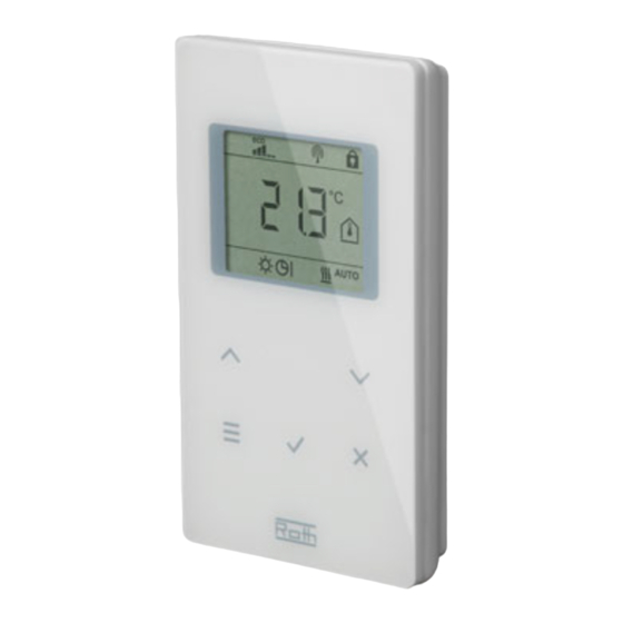
User Manual Roth EnergyLogic Touchline/Wireless Design and function 4.1.2 Wireless room thermostat °C Fig. 4: Design wireless room thermostat left with display, right without display 1 Display 2 Sensor buttons 3 Opening, to open the wireless room thermostat 4 IR-Sensor... - Page 21 User Manual Roth EnergyLogic Touchline/Wireless Design and function The optimal comfort with minimal energy consumption is guaranteed by the Time program and selection of an individual temperature profile for each day provided by the time energy saving mode program. In the wireless room thermostat three different time programs can be (reduced mode) selected and customized.
- Page 22 User Manual Roth EnergyLogic Touchline/Wireless Design and function During PWM control, the opening and closing time of the valves is calculated from the temperature difference between the setpoint and the actual value. The higher this difference, the higher the opening or the closing time.
-
Page 23: Operating And Monitoring Elements
User Manual Roth EnergyLogic Touchline/Wireless Design and function Operating and monitoring elements 4.3.1 Wireless connection module Wireless connection module with LAN CH 1 CH 2 CH 3 CH 4 N N L L 25 26 27 28 29 30 31 32... - Page 24 User Manual Roth EnergyLogic Touchline/Wireless Design and function Push buttons Push buttons Description System Combining several (up to 5) wireless connection modules into a system. Master Define a wireless connection module as master in a system with multiple wireless connection modules. Each system must have one master.
- Page 25 User Manual Roth EnergyLogic Touchline/Wireless Design and function LEDs Description ● Cool: On: C/O-input contact closed Blue LED (cooling mode active) ● On: TB-C/O 24…230V input active (as C/O-input configured) ● On: Switch over heating/cooling by wireless room thermo- stat (C/O-Output active) ●...
-
Page 26: Wireless Room Thermostat With Display
User Manual Roth EnergyLogic Touchline/Wireless Design and function 4.3.2 Wireless room thermostat with display °C °F °C °F RESET TIMEDATETEMP SERV RESET TIMEDATETEMP SERV Fig. 7: Overview display and sensor buttons wireless room thermostat 1 General information such as battery status, energy saving mode, alarms for... - Page 27 User Manual Roth EnergyLogic Touchline/Wireless Design and function Sensor buttons Description Change time and date. 10 s: Cancel ● Addressing 5 s: ● Test addressing. 5 s: Disable/enable operation (key-lock) Activate/deactivate sensor mode 10 s: Specify duration for which this sensor button is occupied with 2 s: a specific function.
- Page 28 User Manual Roth EnergyLogic Touchline/Wireless Design and function Symbols Description Floor temperature (only IR-version) Outdoor temperature (only with accessory) Off (frost protection) Reduced operation Normal operation Time program with external clock Time program 1, 2 and 3 Cooling mode Cooling lock...
-
Page 29: Wireless Room Thermostat Without Display
User Manual Roth EnergyLogic Touchline/Wireless Design and function 4.3.1 Wireless room thermostat without display Fig. 9: Overview operating elements wireless room thermostat 1 LED 2 Rotary knob for setting the setpoint 3 Button for addressing to a wireless connection module... -
Page 30: Installation
User Manual Roth EnergyLogic Touchline/Wireless Installation Installation Wireless connection module NOTE Information on dimensions, see page 113, chapter 14.2.1. Plan on additional space for opening the cover of the wireless connection module. You need approx. 1 cm to the right of the connection module. -
Page 31: Wireless Room Thermostat
User Manual Roth EnergyLogic Touchline/Wireless Installation Wireless room thermostat 5.2.1 Place of installation and general installation notes Information on dimensions, see page 116, chapter 14.3.1. The place of installation for the wireless room thermostat must meet the Conditions for place of... -
Page 32: Wireless Room Thermostat With Display
User Manual Roth EnergyLogic Touchline/Wireless Installation 5.2.2 Wireless room thermostat with display ► Hold the cover of the wireless room thermostat with one hand. Open wireless room ther- mostat ► Open the cover by applying a 5 mm Phillips-tip screwdriver in the hole. - Page 33 User Manual Roth EnergyLogic Touchline/Wireless Installation ► Install the bottom part of the wireless room thermostat with the 2 included Install bottom part screws and plugs. 4 mm Fig. 15: Installation bottom part of wireless room thermostat Insert batteries Fig. 16:...
-
Page 34: Wireless Room Thermostat Without Display
User Manual Roth EnergyLogic Touchline/Wireless Installation Close wireless room thermostat click Fig. 17: Close the wireless room thermostat 5.2.3 Wireless room thermostat without display You need to remove the rotary knob to open and address the wireless room Open wireless room ther- thermostat. - Page 35 User Manual Roth EnergyLogic Touchline/Wireless Installation ► Install the bottom part of the wireless room thermostat. Install bottom part 60 mm Fig. 19: Install lower part ► Insert the batteries in the upper part of the wireless room thermostat. Insert batteries Fig.
-
Page 36: Wireless Room Thermostat With 230 V Connection
User Manual Roth EnergyLogic Touchline/Wireless Installation 5.2.4 Wireless room thermostat with 230 V connection Danger to life from electrical voltage! DANGER Contact with live parts is an immediate danger to life. Damage to the insulation or individual components can be life threatening. - Page 37 User Manual Roth EnergyLogic Touchline/Wireless Installation ► Connect the wireless room thermostat. 230 V~ Fig. 23: Close the wireless room thermostat ► Close the cover of the wireless room thermostat. See page 34. P100011294 E...
-
Page 38: Electrical Connections
User Manual Roth EnergyLogic Touchline/Wireless Electrical connections Electrical connections Safety Danger to life from electrical voltage! DANGER Contact with live parts is an immediate danger to life. Damage to the insulation or individual components can be life threatening. – When insulation is damaged turn off power immediately and arrange for repair. - Page 39 User Manual Roth EnergyLogic Touchline/Wireless Electrical connections Fine-wire conductors must only be used with wire-end ferrules. Fine-wire conductor Fig. 24: Left: Wire-end ferrules with plastic collar right: Wire-end ferrules without plastic collar Strand cross-section L [mm] L1 [mm] [mm²] 0.25 to 0.34...
-
Page 40: Wireless Connection Module
User Manual Roth EnergyLogic Touchline/Wireless Electrical connections Wireless connection module 6.3.1 Connection diagram for wireless connection module with LAN CH 1 CH 2 CH 3 CH 4 CH 5 CH 6 CH 7 CH 8 CH 9 CH 10 CH 11... -
Page 41: Connection Diagram For Wireless Connection Module Without Lan
User Manual Roth EnergyLogic Touchline/Wireless Electrical connections 6.3.1 Connection diagram for wireless connection module without LAN CH 1 CH 2 CH 3 CH 4 CH 5 CH 6 CH 7 CH 8 CH 9 CH 10 CH 11 CH 12... - Page 42 User Manual Roth EnergyLogic Touchline/Wireless Electrical connections Connect wires Danger from electrical voltage on terminals 01 to 10! DANGER There is a direct danger to life from contact with live parts. – Before any work, disconnect the wireless connection module and the peripheral devices from the mains and secure against reactivation.
- Page 43 User Manual Roth EnergyLogic Touchline/Wireless Electrical connections ► Connect the transformer to the 24 V input terminals 11 and 12. Connect transformer ATTENTION Malfunctioning due to improper connection! Improper connection may cause malfunction of the system. – Each wireless connection module must have a separate transformer.
- Page 44 User Manual Roth EnergyLogic Touchline/Wireless Electrical connections ► Connect the thermal actuators to the following terminals: Connect thermal actuators – 4-channel version: terminals 25 to 36 for max. 6 actuators – 8-channel version: terminals 25 to 56 for max. 12 actuators –...
- Page 45 C/O-input, control with 230 V Terminal 10 Voltage ON: cooling ON Voltage OFF: cooling OFF 1 e.g. Roth heat pump Terra Compact ATTENTION Do not interchange the connection to terminals 09 (L) and 10 (N)! Improper connection may cause malfunctioning of the system.
- Page 46 User Manual Roth EnergyLogic Touchline/Wireless Electrical connections The TB-input can be used for temperature monitoring by an external maxi- TB-input for temperature mum temperature limiter. monitoring (LAN versions only) ► Connect the signal of the external temperature limiter to terminals 09 and Fig.
- Page 47 User Manual Roth EnergyLogic Touchline/Wireless Electrical connections The output "c/o out" is a configurable output for cooling (C/O: Change-Over) C/O- or burner output, or burner start. potential free contact (LAN versions only) ► Attach a refrigeration unit or a burner on the terminals 07 and 08. The radio system must be configured for either application.
- Page 48 17 and 18 of the wireless connection module. Fig. 39: Humidity input Terminal 17 and 18, contact closed: maximum allowable humidity exceeded, cooling OFF contact open: maximum allowable humidity not exceeded, cooling at demand ON 1 Roth dew-point monitor (material number: 1135000327) P100011294 E...
- Page 49 User Manual Roth EnergyLogic Touchline/Wireless Electrical connections ► Connect the LAN-network as show below. Connection LAN-network RJ-45 RJ-12 microSD LAN Options 1.) PowerLAN 2.) LAN Router 3.) WLAN Router Fig. 40: LAN-network P100011294 E...
- Page 50 User Manual Roth EnergyLogic Touchline/Wireless Electrical connections ► Put on the cover as shown below Install cover ► Insert the plug from the transformer into the outlet. ► At the wireless connection module the Power LED must light. Power click Fig.
-
Page 51: Commissioning And Operation
User Manual Roth EnergyLogic Touchline/Wireless Commissioning and operation Commissioning and operation The commissioning of the control system comprises the following steps: Steps during commissioning ► Execute the addressing between wireless connection module and wireless room thermostats. ► Test addressing. ►... -
Page 52: Address One Wireless Room Thermostat To One Radio Channel
User Manual Roth EnergyLogic Touchline/Wireless Commissioning and operation 7.1.1 Address one wireless room thermostat to one radio channel One wireless room thermostat shall be addressed to radio channel CH 1. Example ► Press push button CH 1 of the wireless connection module. -
Page 53: Address Several Wireless Room Thermostats To One Radio Channel (Sensor Mode)
User Manual Roth EnergyLogic Touchline/Wireless Commissioning and operation 7.1.3 Address several wireless room thermostats to one radio channel (sensor mode) When several wireless room thermostats in sensor mode are addressed to one channel, then all actual measured temperatures will be used to calculate the average room temperature. - Page 54 User Manual Roth EnergyLogic Touchline/Wireless Commissioning and operation ► Press the sensor buttons of the wireless room thermostat for Second wireless room 10 seconds simultaneously. thermostat, set sensor mode ► The display shows "– – – –" first permanently for 5 seconds and then blinks for another 5 seconds.
-
Page 55: Test Addressing
User Manual Roth EnergyLogic Touchline/Wireless Commissioning and operation ► Delete the connection of the wireless room thermostat according to page Version B 55, chapter 7.1.5. ► Press sensor button of the wireless room thermostat 5 seconds. ► The display shows "SENS" and symbol ►... -
Page 56: Combine Several Wireless Connection Modules Into A System
User Manual Roth EnergyLogic Touchline/Wireless Commissioning and operation 7.1.6 Combine several wireless connection modules into a system Up to five wireless connection modules can be combined into one system. One of the wireless connection modules have to be defined as master. At factory all wireless connection modules are configured as slave. -
Page 57: Internal System Grid Repeater
User Manual Roth EnergyLogic Touchline/Wireless Commissioning and operation NOTE All central plant devices such as a central pump, burner control, C/O-signal for a heat pump etc. are connected to the wireless connection module "Master". To a wireless connection module "Slave" only a local pump, if any, is connected. - Page 58 User Manual Roth EnergyLogic Touchline/Wireless Commissioning and operation If there is a wireless connection module "Slave" out of reach, you can inte- Integrate wireless connec- grate this wireless connection module into the system network via the internal tion modules into the sys- repeater.
-
Page 59: Zones
User Manual Roth EnergyLogic Touchline/Wireless Commissioning and operation Zones Each wireless connection module can be divided in up to 3 zones. Applications for zoning Zones can be used for the following applications: ● Within one zone the modes of operation, "Off (frost protection)", "Eco", "Normal Operation"... -
Page 60: Delete Assignment Of A Radio Channel Or Several Radio Channels To A Zone
User Manual Roth EnergyLogic Touchline/Wireless Commissioning and operation ► Press push button Zone at the wireless connection module briefly. Build third zone ► The yellow LED indicating the third zone and the CH LEDs for channels not yet assigned to a zone blink. -
Page 61: Change Setpoints
User Manual Roth EnergyLogic Touchline/Wireless Commissioning and operation Change setpoints 7.3.1 Set room temperature The wireless room thermostat is in stand-by mode. ► Press any button on the wireless room thermostat for 2 seconds. ► The display changes into operation mode. The setpoint blinks. -
Page 62: Select Mode Of Operation
User Manual Roth EnergyLogic Touchline/Wireless Commissioning and operation NOTE If for the stand-by mode for the parameter P-01 the option "Actual value" is selected, the actual value of the IR sensor (floor temperature) will be dis- played for the first four seconds. Afterwards the actual value of the room temperature sensor is displayed. - Page 63 User Manual Roth EnergyLogic Touchline/Wireless Commissioning and operation ► Press the sensor button , to confirm the new mode of operation. – If no sensor button is pressed, the selection is interrupted after 10 sec- onds and the wireless room thermostat returns into stand-by mode. The new mode of operation is not saved.
-
Page 64: Set Time And Date
User Manual Roth EnergyLogic Touchline/Wireless Commissioning and operation Set time and date For proper functioning of the plant it is necessary to set the time and date of At commissioning each wireless connection module. During addressing of the first wireless room thermostat to a wireless connec- tion module, the setting of the time and date is automatically prompted. -
Page 65: Time Programs
User Manual Roth EnergyLogic Touchline/Wireless Commissioning and operation Time programs 7.6.1 Overview of the three time programs The wireless connection module has three different types of time programs that can be changed. The time programs are the same for all room thermo- stats. -
Page 66: Select Time Program
User Manual Roth EnergyLogic Touchline/Wireless Commissioning and operation NOTE The temperature difference between "Normal operation" and "Reduced operation" can be set individually for each wireless room thermostat. The factory setting is 3 K. In operating mode "Reduced operation", the display shows the setpoint of the operating mode "Normal operation". -
Page 67: Change Time Program
User Manual Roth EnergyLogic Touchline/Wireless Commissioning and operation 7.6.4 Change time program NOTE The sequence of the switching points has to be fix and ascending: Switching point Switched-on period 1 reduced normal normal reduced Switched-on period 2... - Page 68 User Manual Roth EnergyLogic Touchline/Wireless Commissioning and operation Time program Pro1 has to be changed. Change an existing time program The wireless room thermostat is in stand-by mode. ► Press any button on the wireless room thermostat for 2 seconds.
- Page 69 User Manual Roth EnergyLogic Touchline/Wireless Commissioning and operation Time program Pro1 is selected. The factory settings need to be changed. Time program Pro1 – change first switched-on period ► Press sensor button . The display shows the time of the first switching point for "reduced to normal".
-
Page 70: Reset Time Programs To Factory Settings
User Manual Roth EnergyLogic Touchline/Wireless Commissioning and operation ► Select one of the following options: Time program Pro2 – Press sensor button , to skip time program Pro2 and to go to time program Pro3. – Press sensor button , to leave the time program Pro2. The display shows P-04. -
Page 71: Eco"-Indicator
User Manual Roth EnergyLogic Touchline/Wireless Commissioning and operation "eco"-Indicator The "eco"-indicator displays the relative energy consumption of the plant. The "eco"- indicator has five levels. The "eco"-level is depending on the following factors: ● Setpoint ● Actual room temperature ●... -
Page 72: Lock / Unlock Operation Of Wireless Room Thermostat
User Manual Roth EnergyLogic Touchline/Wireless Commissioning and operation The duration for the function of the sensor button is set as follows: Specify duration (party function) ► Press the sensor button for 2 seconds. The display shows P-0H. ► Press the sensor button to set the time. -
Page 73: Software Update With Micro Sd-Card
The latest software release can be obtained at any time from the Roth webpage. Please read the accompanying instructions before executing the software update. P100011294 E... -
Page 74: Reset Values To Factory Setting (Reset)
User Manual Roth EnergyLogic Touchline/Wireless Reset values to factory setting (reset) Reset values to factory setting (reset) Reset radio system to factory settings With the following procedure the wireless room thermostat and the relevant wireless connection module can be reset to factory settings. -
Page 75: Parameter Descriptions
User Manual Roth EnergyLogic Touchline/Wireless Parameter descriptions Parameter descriptions The menu is divided in a user menu and a service menu. The user menu is freely accessible. The service menu can only be entered through a service code. NOTE Parameters can only be set by a wireless room thermostat at the same time. - Page 76 User Manual Roth EnergyLogic Touchline/Wireless Parameter descriptions P-30 Parameter Description Parameters for all wire- less room thermostats P-31 Set increment for room temperature setpoint adjustment. P-32 Set temperature for frost protection function. P-33 Set unit for temperature. P-34 Set dead-zone for change-over between heating and cooling.
-
Page 77: User Menu
User Manual Roth EnergyLogic Touchline/Wireless Parameter descriptions P-60 Parameter Description Control parameters P-61 Configure Eco or N/R input. P-62 Configure C/O in-/TB-input. P-63 Select control of pump "local" or "Master-wireless connection module" (only with activated communication between wireless connection modules). - Page 78 User Manual Roth EnergyLogic Touchline/Wireless Parameter descriptions Parameter Description P-01 Set display in stand-by-mode. • Factory settings: room temperature Operation ► Press sensor button , to select the displayed value change: room-, floor-, outdoor temperature or time. Floor and outdoor temperature are only available with certain versions and ac- cessories.
- Page 79 User Manual Roth EnergyLogic Touchline/Wireless Parameter descriptions Parameter Description P-06 Set display for stand-by-mode. (max. battery saving mode) To minimize battery consumption the display can be switched off in stand-by- mode. Only the symbol "low battery" will be shown when applicable.
- Page 80 User Manual Roth EnergyLogic Touchline/Wireless Parameter descriptions Parameter Description P-10 Use this parameter to specify the function of the sensor button You may choose between the following functions: ● P-9H: Party function ● H-C: Direct switching heating/cooling ● Display of the floor temperature (for wireless room thermostats with IR only) ●...
-
Page 81: Service Menu
User Manual Roth EnergyLogic Touchline/Wireless Parameter descriptions Service menu 9.3.1 Enter service menu The service menu is protected with a service code. This service code can P-SE be changed with parameter P-36. See parameter description P-36, page 86. -
Page 82: General Parameters
User Manual Roth EnergyLogic Touchline/Wireless Parameter descriptions 9.3.3 P-20 "General parameters" For the following parameter descriptions the relevant parameter was already selected. The display shows P-xx. Parameter Description P-21 Show software-version of wireless room thermostat. Operation ► Press sensor button . - Page 83 User Manual Roth EnergyLogic Touchline/Wireless Parameter descriptions Parameter Description P-24 Reset parameter to factory settings. Parameters are partly stored in the wireless connection module and partly in the wireless room thermostat. ● Options – 0: Not active, no reset will be executed.
-
Page 84: Parameters For All Wireless Room Thermostats
User Manual Roth EnergyLogic Touchline/Wireless Parameter descriptions 9.3.4 P-30 "Parameters for all wireless room thermostats" Any change of the following parameters will be transmitted to all wireless room thermostats that are assigned to the wireless connection module. It can take up to 10 minutes before all wireless room thermostats that are in stand-by-mode have received the transmitted data. - Page 85 User Manual Roth EnergyLogic Touchline/Wireless Parameter descriptions Parameter Description P-33 Set unit for temperature. ● Factory settings: Option "0" ● Options: – 0: °C – 1: F Operation ► Press sensor button . The display shows 0. ► Press sensor button , to select option 1.
- Page 86 User Manual Roth EnergyLogic Touchline/Wireless Parameter descriptions Parameter Description P-35 Change service code for service menu. ● Factory settings: 1234 Operation ► Press sensor button . The display shows 1234. ► Press sensor button , to change the service code. Confirm each selected digit with sensor button ►...
-
Page 87: Parameters For Individual Wireless Room Thermostats
User Manual Roth EnergyLogic Touchline/Wireless Parameter descriptions Parameter Description P-38 Deactivate or activate automatic time settings. NOTE Only for LAN- versions with active internet connection: The wireless connection module can get the current time from the internet to keep the date and time up to date. - Page 88 User Manual Roth EnergyLogic Touchline/Wireless Parameter descriptions Parameter Description P-42 Set floor temperature correction of wireless room thermostat with integrated IR- sensor. ● Factory settings: Option "0" ● Options: – 0, standard setting: suitable for wood floors – 1, average compensation: suitable for plastic floorings –...
- Page 89 User Manual Roth EnergyLogic Touchline/Wireless Parameter descriptions Parameter Description P-44 Set reduction of room temperature for "Eco" function. The frost protection function has a higher priority than the Eco function. See pa- rameter description P-32, page 84. Independently of the set value, the reduced temperature cannot lower than 11 °C and not higher than 21 °C.
- Page 90 User Manual Roth EnergyLogic Touchline/Wireless Parameter descriptions Parameter Description P-46 Activate or deactivate "setpoint sharing within one zone". Refer to also page 121, chapter 16. Setpoint sharing is typically used for large rooms that have different temperature profiles for different parts of the room. The room is divided into several heating zones each with its own wireless room thermostat.
- Page 91 User Manual Roth EnergyLogic Touchline/Wireless Parameter descriptions Parameter Description P-48 Activate or deactivate master function of a wireless room thermostat. One wireless room thermostat per wireless connection module or per tone can be defined as master. With this master wireless room thermostat the modes of opera- tion "Off (frost protection)", "reduced operation", "normal operation"...
-
Page 92: Plant- And Topology Related Parameter
User Manual Roth EnergyLogic Touchline/Wireless Parameter descriptions 9.3.6 P-50 "Plant- and topology related parameter" Parameter Description P-51 Set priorities for change-over of heating/cooling and configure output for heat- ing/cooling or burner start. ATTENTION If communication between wireless connection modules has been selected, then the settings of P-51 must be the same at all wireless connection modules with a wire- less room thermostat. - Page 93 User Manual Roth EnergyLogic Touchline/Wireless Parameter descriptions Parameter Description P-52 (continued) Operation ► Press sensor button . The display shows 0. ► Press sensor button , to select option 0 or 1. ► Select one of the following options: –...
-
Page 94: Control Parameters
User Manual Roth EnergyLogic Touchline/Wireless Parameter descriptions 9.3.7 P-60 "Control parameters" Parameter Description P-61 Configure Eco or N/R input. With the Eco-input it is possible to override the actual mode of operation of all wire- less room thermostats with an additional main switch or SMS-modem. Depending on the selected option this function can either switch between "normal"... - Page 95 User Manual Roth EnergyLogic Touchline/Wireless Parameter descriptions Parameter Description P-62 Configure C/O in-/TB-input. The TB-inputs detects a voltage between 24 V and 230 V. ● C/O in-/TB-input: As soon as a voltage is detected the mode of operation of the wireless connection module is changed to cooling.
- Page 96 User Manual Roth EnergyLogic Touchline/Wireless Parameter descriptions Parameter Description P-63 Select control of pump "local" or "Master-wireless connection module". This parameter can only be configured when several wireless connection modules communicate wirelessly. ● Factory settings: ● Options – 0: Pump output is configured as local pump. The pump will be switched on only when heating or cooling demand is caused by one of the channels of by the wireless connection module to which the pump is connected.
- Page 97 User Manual Roth EnergyLogic Touchline/Wireless Parameter descriptions Parameter Description P-65 Select control algorithm. For efficient temperature control one can select between three control algorithms and an optimized actuator control. For optimized actuator control see next parame- ter description P-66. The following control algorithms can be selected: On/Off-control, PWM control for heat pump in combination with surface heating with high inertia (slow systems) and PWM control for surface heating with medium inertia (medium-lag systems) e.g.
- Page 98 User Manual Roth EnergyLogic Touchline/Wireless Parameter descriptions Parameter Description P-66 Activate or deactivate function "optimized actuator control". The optimized actuator control is a specially developed actuator control that saves energy. This control also replaces a quasi-proportional control. At the start the thermal actuator will receive a 100% signal for a certain period. After this heat up period the actuator receives pulse/pause signal that is depending on the ambient temperature, configured with the options of this P-66.
-
Page 99: Cleaning And Maintenance
User Manual Roth EnergyLogic Touchline/Wireless Cleaning and maintenance Parameter Description P-67 (continued) Operation ► Press sensor button . The display shows 0. ► Press sensor button , to select option 0 or 1. ► Select one of the following options: –... -
Page 100: Troubleshooting
User Manual Roth EnergyLogic Touchline/Wireless Troubleshooting 11 Troubleshooting The following tables describe possible problems and measures to remedy. Contact your installer for any issues, which cannot be resolved with to the following description. See page 2. 11.1 Wireless connection module... -
Page 101: Wireless Room Thermostat With Display
User Manual Roth EnergyLogic Touchline/Wireless Troubleshooting 11.2 Wireless room thermostat with display Problem Possible cause Remedy To be executed by Battery almost empty. Replace batteries. User bAtt Battery critically low. Radio Replace batteries immedi- User connection between wire- ately. See also page 32, open... -
Page 102: Procedure For Err1 Or Err2
User Manual Roth EnergyLogic Touchline/Wireless Troubleshooting 11.2.1 Procedure for Err1 or Err2 Once the display shows " Err1" or " Err2", the wireless room thermostat can no longer be assigned to a wireless connection module. ► Press the sensor buttons of the wireless room thermostat for 10 seconds. -
Page 103: Wireless Room Thermostat Without Display
User Manual Roth EnergyLogic Touchline/Wireless Troubleshooting 11.3 Wireless room thermostat without display Interference/Display Possible cause Measure To be performed by LED flashes continually Battery too weak Exchange batteries. Operator Table 23: Troubleshooting: Wireless room thermostat without display 11.4 FAQs Note The setpoint temperature cannot be Check if the operating mode "Normal operation"... -
Page 104: Tips And Tricks
User Manual Roth EnergyLogic Touchline/Wireless Waste disposal Note ● Check if addressing was performed correctly. See page 55, chapter The LED CH is not lit when the target value is set after addressing or com- 7.1.4. ● missioning. If the LED CH at the wireless connection module flashes, perform ad- dressing again. -
Page 105: Accessories
User Manual Roth EnergyLogic Touchline/Wireless Accessories 13 Accessories 13.1 External antenna To improve the transmission of a wireless connection module, e.g. when the wireless connection module is installed in a metal cabinet, an external anten- na can be installed. See page 23, Fig. 5. -
Page 106: External Repeater
User Manual Roth EnergyLogic Touchline/Wireless Accessories 13.2 External Repeater If a radio connection between the wireless connection module and wireless Function room thermostat or between the wireless connection modules cannot be achieved, you may use an external repeater. This leads to a larger range between the wireless connection modules. -
Page 107: Install The External Repeater
User Manual Roth EnergyLogic Touchline/Wireless Accessories 13.2.1 Install the external repeater ► Place the external repeater between the wireless connection module and wireless room thermostat. ► Open the housing with a flat-tip screwdriver. Fig. 49: Open housing ► Route the line of the plug-in mains unit into the housing from behind. -
Page 108: Assign The External Repeater To A Wireless Room Thermostat
User Manual Roth EnergyLogic Touchline/Wireless Accessories ► Close the cover of the external repeater. Fig. 52: Close the housing ► Push the plug-in mains adapter into a socket. Once the external repeater is supplied with power, the green LED will light up. -
Page 109: Test The External Repeater's Radio Connection
User Manual Roth EnergyLogic Touchline/Wireless Accessories ► Press the sensor buttons of the wireless room thermostat simul- taneously for 5 seconds. The green and yellow LEDs on the external re- peater light up. The LED CH 1 at the wireless connection module stops blinking. -
Page 110: Assign The External Repeater To A Wireless Connection Module
User Manual Roth EnergyLogic Touchline/Wireless Accessories 13.2.5 Assign the external repeater to a wireless connection module The system comprises a wireless connection module "Master" and up to four wireless connection modules "Slave". Since the distance is too far, the wire- less connection modules "Slave"... -
Page 111: Check External Repeater Assignment
User Manual Roth EnergyLogic Touchline/Wireless Accessories 13.2.7 Check external repeater assignment Perform the following step to check if an external repeater is assigned to a room operating network or a system network. ► Press the push button at the external repeater briefly. -
Page 112: Deactivate Leds At The External Repeater
User Manual Roth EnergyLogic Touchline/Wireless Accessories 13.2.9 Deactivate LEDs at the external repeater If you are bothered by the LEDs being lit, you can switch off the LEDs as follows. ► Remove the covers of the external repeater. ► There is a push button in the upper area of the PCB. Keep this push button pressed for 5 seconds. -
Page 113: Technical Data
User Manual Roth EnergyLogic Touchline/Wireless Technical data 14 Technical data 14.1 Radio system Radio frequency 868 MHz (coded) Transmission rate 50 kbit/s Direction Bidirectional ● Reach 40 m in "normal housings" or detached houses, depending on envi- ronment ● 200 to 300 m in free field, depending on obstacles, surfaces, local... -
Page 114: Electrical Connections
User Manual Roth EnergyLogic Touchline/Wireless Technical data ● Dimensions(width x height x depth) 4-channel: 225 mm x 74 mm x 52 mm ● 8-channel: 290 mm x 74 mm x 52 mm ● Dimensions connection module without 12-channel: 355 mm x 74 mm x 52 mm ●... -
Page 115: Outputs
User Manual Roth EnergyLogic Touchline/Wireless Technical data 14.2.4 Outputs ● Max. number of thermal actuators 4-channel: 6 (2 channels / 2 actuators, 2 channels / 1 actuator) ● 8-channel: 12 (4 channels / 2 actuators, 4 channels / 1 actuator) ●... -
Page 116: Wireless Room Thermostat With Display
User Manual Roth EnergyLogic Touchline/Wireless Technical data 14.3 Wireless room thermostat with display 14.3.1 Construction and dimensions 21 21 19.5 Fig. 54: Dimensions wireless room thermostat with display (all dimensions in mm) Dimensions(width x height x depth) 65 mm x 117 mm x 19.5 mm... -
Page 117: Performance Data
User Manual Roth EnergyLogic Touchline/Wireless Technical data 14.3.4 Performance data Setting range setpoint +5 to +30 °C 0,1 K/0,5 K Accuracy (resolution) Cycle time Ca. 10 min Dead-time Ca. 50 s ● Transmission interval 1 … 10 min ● 1 min after change of setpoint or mode of operation ●... -
Page 118: Wireless Room Thermostat Without Display
User Manual Roth EnergyLogic Touchline/Wireless Technical data 14.4 Wireless room thermostat without display 14.4.1 Construction and dimensions Fig. 55: Dimensions wireless room thermostat without display (all dimensions in mm) Dimensions(width x height x depth) 84 mm x 87 mm x 20 mm... -
Page 119: Menu Structure
User Manual Roth EnergyLogic Touchline/Wireless Menu structure 15 Menu structure 10 s time-out Stand-by- Operation mode (changed value mode (save point) is saved) 10 s time-out (changed value is NOT saved) Operation mode Any button 2 s (only one button) - Page 120 User Manual Roth EnergyLogic Touchline/Wireless Menu structure 20 min Time-out Stand-by- mode 1 min Time-out Any button 2 s (only one button) Operation mode User menu P-01 > 5 s P-01 Change value Save value P-02 P-SE P-01 Enter Service menu...
-
Page 121: Plant Examples And Communication
User Manual Roth EnergyLogic Touchline/Wireless Plant examples and communication 16 Plant examples and communication 16.1 Plant examples with one wireless connection module CH 2 CH 3 CH 4 CH 5 CH 6 CH 7 CH 8 CH 1 Fig. 58:... - Page 122 User Manual Roth EnergyLogic Touchline/Wireless Plant examples and communication SENS SENS P-46 P-46 P-46 P-46 CH 2 CH 3 CH 4 CH 5 CH 6 CH 7 CH 8 CH 1 Fig. 60: Radio channel groups with zone building 1 Zone 1 with average temperature building...
- Page 123 User Manual Roth EnergyLogic Touchline/Wireless Plant examples and communication CH 2 CH 3 CH 4 CH 5 CH 6 CH 7 CH 8 CH 1 Fig. 62: Wireless room thermostat as "Master" for changing mode of operation – Wireless room thermostat as "Master" with own zone.
-
Page 124: Plant Examples With Up To Five Wireless Connection Modules
User Manual Roth EnergyLogic Touchline/Wireless Plant examples and communication 16.2 Plant examples with up to five wireless connection modules Slave CH 2 CH 3 CH 4 CH 5 CH 6 CH 7 CH 8 CH 1 SENS SENS P-46 P-46... -
Page 125: Index
User Manual Roth EnergyLogic Touchline/Wireless Index Index A Cleaning .............. 99 Code Accessories Access code public spaces (P-36) ....86 External antenna ......... 105 Service menu (P-35) ........86 External repeater ......... 106 Commissioning ........... 51 Type designation ........... 17 Set time and date .......... - Page 126 User Manual Roth EnergyLogic Touchline/Wireless Index Display elements Parameter P-10 ..........80 Wireless room thermostat with display ..26 Specify duration ..........72 H Wireless room thermostat without display ..29 E Health hazards ........... 15 eco-indicator ............71 Heat pump ............ 45, 48 eco–indicator...
- Page 127 User Manual Roth EnergyLogic Touchline/Wireless Index M Function test radio connection between connection modules ........56 Maintenance ............99 How to detect that no zones are built .... 60 Master wireless room thermostat (P-48) .... 91 Inactive sensor buttons in sensor mode ..54 Material numbers Information regarding software updates ..
- Page 128 User Manual Roth EnergyLogic Touchline/Wireless Index Operation ............51 Select Modes of operation ........62 Mode of operation ......... 62 Operation mode wireless room thermostat ..28 Parameter group ........... 81 Optimized actuator control ......... 22 Sensor button Optimized actuator control (P-66 ) ..... 98 Sound on/off (P-07) ........
- Page 129 User Manual Roth EnergyLogic Touchline/Wireless Index T P-60 – Control parameters ...... 77, 94 Reduction of room temperature (P-44) ..89 TB-input Reset to factory settings (P-24) ..... 83 Temperature monitoring ........ 46 Select local or master pump (P-63) ....96 Technical data Select NO/NC actuators (P-64) .....
- Page 130 User Manual Roth EnergyLogic Touchline/Wireless Index Troubleshooting ..........100 LED description ..........24 Lost radio connection........101 LEDs ............. 23 Radio signal lost ......... 102 Material numbers .......... 16 Wireless connection module ....... 100 Monitoring elements........23 Wireless room thermostat with display ..101 Operating elements........
- Page 131 User Manual Roth EnergyLogic Touchline/Wireless Index Technical data ..........116 Wireless room thermostat with display Troubleshooting ........... 101 Display elements ........... 26 Wireless room thermostat without display Wiring notes ............38 Z Close housing ..........35 Display elements ........... 29 Zones ..............
-
Page 132: Factory Settings Parameters
User Manual Roth EnergyLogic Touchline/Wireless Plant examples and communication Factory settings parameters We recommend that you enter your settings in the following tables, e.g. for reset. After a reset of the radio connection module, all settings are reset to factory settings. - Page 133 User Manual Roth EnergyLogic Touchline/Wireless Factory settings parameters Parameter Description Factory settings P-41 Set wall temperature correction of wireless room thermo- stat. P-42 Set floor temperature correction of wireless room thermo- stat with integrated IR-sensor. P-43 Set maximum floor temperature of wireless room thermo- 35 °C...
-
Page 134: Factory Settings Time Program
User Manual Roth EnergyLogic Touchline/Wireless Plant examples and communication Factory settings time program 16:30...23:00 06:00...08:30 11:30...13:30 06:00...08:30 11:30...13:30 16:30...23:00 06:00...08:30 11:30...13:30 16:30...23:00 06:00...08:30 16:30...23:00 06:00...23:00 OFF – 06:00...08:30 11:30...13:30 16:30...23:00 06:00...08:30 11:30...13:30 16:30...23:00 06:00...23:00 00:00...00:00 00:00...00:00 06:00...23:00 OFF 00:00...00:00 06:00...23:00 00:00...00:00...
Need help?
Do you have a question about the EnergyLogic Touchline/wireless and is the answer not in the manual?
Questions and answers