Hughes HX200 Installation Manual
Satellite router
hx system
Hide thumbs
Also See for HX200:
- User manual (20 pages) ,
- Installation manual (160 pages) ,
- Installation procedure (18 pages)

Related Manuals for Hughes HX200


Summary of Contents for Hughes HX200
-
Page 1: Installation Guide
HX System Satellite Router Installation Guide Model: HX200 Draft 1038054-0001 Revision A.04 - Inspection Draft October 27, 2008... - Page 2 Hughes Network Systems, LLC has made every effort to ensure the correctness and completeness of the material in this document. Hughes Network Systems, LLC shall not be liable for errors contained herein. The information in this document is subject to change without notice. Hughes Network Systems, LLC makes no warranty of any kind with regard to this material, including, but not limited to, the implied warranties of merchantability and fitness for a particular purpose.
-
Page 3: Understanding Safety Alert Messages
Understanding safety alert messages Safety alert messages call attention to potential safety hazards and tell you how to avoid them. These messages are identified by the signal words DANGER, WARNING, CAUTION, or NOTICE, as illustrated below. To avoid possible property damage, personal injury, or in some cases possible death, read and comply with all safety alert messages. -
Page 4: Safety Symbols
Safety symbols The generic safety alert symbol calls attention to a potential personal injury hazard. It appears next to the DANGER, WARNING, and CAUTION signal words as part of the signal word label. Other symbols may appear next to DANGER, WARNING, or CAUTION to indicate a specific type of hazard (for example, fire or electric shock). -
Page 5: Table Of Contents
HX200 features........3... - Page 6 Uploading the SBC configuration file to the HX200 ..25 Commissioning the HX200 ......27 Chapter 4 Completing the installation .
- Page 7 HX200 LEDs ........73...
- Page 8 Netscape ......... .112 Appendix E HX200 transmitter and receiver specifications..115 Appendix F Conforming with standards and directives .
- Page 9 2. HX200 installation kit components ........9...
- Page 10 29. System Status indicator reporting a problem ......45 30. System Status page ..........47 31.
- Page 11 65. TCP/IP Properties - Windows 98SE and Me ......108 66. Entering the satellite router IP address .......109 Appendix D 67.
- Page 12 • Figures 1038054-0001 Revision A.04 - Inspection Draft...
- Page 13 13. HX200 Receiver Specifications ........115...
- Page 14 • Tables 1038054-0001 Revision A.04 - Inspection Draft...
-
Page 15: Introduction
This chapter discusses the following topics: • Scope on page 1 • Related publications on page 1 • HX200 satellite router overview on page 2 • HX200 rack mount kit on page 3 • HX200 features on page 3 • Satellite router specifications on page 5 •... -
Page 16: Hx200 Satellite Router Overview
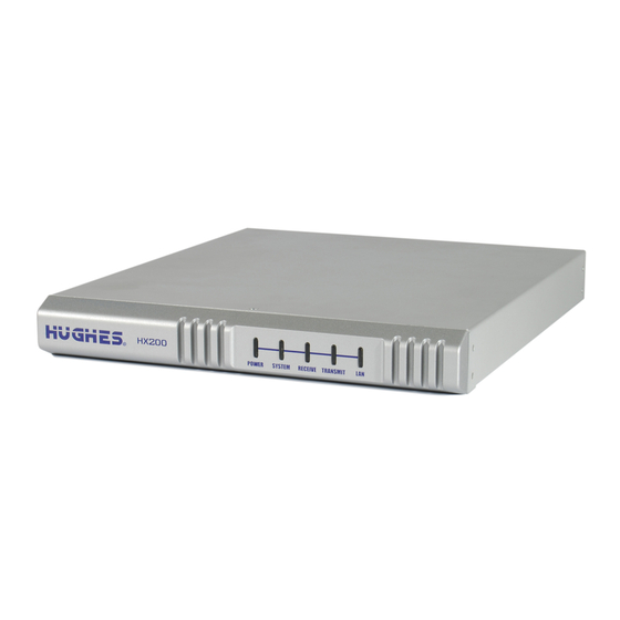
• Remote Terminal Installation Guide, Model HX150, (1037125-0001) • Satellite Router User Guide, Model HX200 (1038055-0001) HX200 satellite router The HX200, as shown in Figure 1 on page 3, is a high-performance satellite router designed to support overview high-bandwidth links with mesh/star capability and QoS features such as Min/Max CIR together with dynamic alllocation of bandwidth. -
Page 17: Hx200 Rack Mount Kit
Figure 1: HX200 satellite router (front and back) HX200 rack mount kit The HX200 equipment rack consists of an industry standard 1U rack-mountable enclosure. HX200 features Low cost self-hosted device HX terminal with 400MHz MIPS processor • Transmission types: – Linear Ku-band –... -
Page 18: Transmission Types
Component Part Number 2W Tigris (India-C) 1028050-0006 2W MTI (Extended-C) 1034468-0002 DVB-S2 compliant outroute The HX200 receives a single Digital Video Braodcast - second generation (DVB-S2) compliant outroute. For detailed Chapter 1 • Introduction 1038054-0001 Revision A.04 - Inspection Draft... -
Page 19: Mobility
• 48V power supply DC voltage input port for supporting > 5W radios Mechanical The HX200 includes an industry standard 1U rack-mountable enclosure. Satellite router Table 5 lists the specifications for the HX200 satellite router. specifications Table 5: HX200 satellite router specifications Product element Specification Physical Interfaces... -
Page 20: Installation And Commissioning
Two Ethernet ports supporting 10BaseT or 100BaseT operation, RJ45-switched Telephone line port Installation and The installation and commissioning of the HX200 satellite router is a multi-step process involving two pieces of equipment—the commissioning HX200 satellite router and the associated transport device. The workflow and chapter reference numbers for the process steps follow. -
Page 21: Contact Information
4. Connecting the satellite router a computer Chapter 4 on page 37 Commissioning is the process of registering an HX200 satellite router for service. During the commissioning process you may use auto selection or manual entry of parameters. • Auto Selection - Allows you to choose the Network Access Provider (NAP) from a predetermined list of providers. - Page 22 Chapter 1 • Introduction 1038054-0001 Revision A.04 - Inspection Draft...
-
Page 23: Assembling And Connecting Hx200 Hardware
• Powering up and observing the LEDs on page 13 Preparing for the installation Items required for To install an HX200 satellite router, first ensure that you have all the items shown in Figure 2. These items are provided in the installation HX200 installation kit. -
Page 24: Confirming Installer Laptop And Site Requirements
(if instructed to install sbc.cfg it). Remote site requirements IP devices that will be connected to an HX200 satellite router must implement the standard TCP/IP stack and provide an Ethernet interface; otherwise there is no constraint to the platforms and operating systems of devices attached to the satellite routers. -
Page 25: Conducting The Site Survey
Figure 3: Connecting the receive and transmit cables to the satellite router The HX200 offers two radio transmit options: saturated or linear. The operator may select only one radio transmit option at any time. There are potential ramifications to both software and hardware if a cable is secured to the incorrect output connector or if cables are connected to both outputs. -
Page 26: Connecting The Ethernet And Power Cables
2. Connect the installer PC to the satellite router with an Ethernet cable. Make sure no Ethernet routers or switches are currently connected between the satellite router and the installer PC. Chapter 2 • Assembling and connecting HX200 hardware 1038054-0001 Revision A.04 - Inspection Draft... -
Page 27: Powering Up And Observing The Leds
3. Connect the power cable. Note: A surge protector is recommended. Note: Do not connect any devices to the HX200 at this time. Connect serial and Ethernet devices to the device only after it is fully installed and commissioned. CAUTION Do not connect or disconnect the Tx or Rx IFL cable while the IDU is powered on;... - Page 28 Chapter 2 • Assembling and connecting HX200 hardware 1038054-0001 Revision A.04 - Inspection Draft...
-
Page 29: Commissioning The Hx200 Satellite Router
2. Type http://192.168.0.1/fs/registration/ in the browser’s address or location bar and setup.html press E to access the Broadband Satellite Setup screen NTER shown in Figure 4. Chapter 3 • Commissioning the HX200 satellite router 1038054-0001 Revision A.04 - Inspection Draft... -
Page 30: Hx200 Broadband Satellite Setup Screen
VSAT Transmit, LAN, and management parameters. These parameters may be provided to you in an installation specification, work order, or in another form of communication from the installation point-of-contact. Chapter 3 • Commissioning the HX200 satellite router 1038054-0001 Revision A.04 - Inspection Draft... -
Page 31: Spreading
Commissioning page, an error message displays and the form can not be submitted until the error is corrected. Spreading The HX200 Manual Commissioning page is not only used to specify the transmit radio wattage, it is also used to enable or disable spreading (Figure 5). -
Page 32: Spreading Disabled
Figure 6: Sample of allowed inroute symbol rates with spreading disabled Spreading enabled 1. From the satellite router’s Advanced web page, click the link. This link displays the Transmitter Allowed Inroutes → Chapter 3 • Commissioning the HX200 satellite router 1038054-0001 Revision A.04 - Inspection Draft... -
Page 33: Sample Of Allowed Inroute Symbol Rates With Spreading Enabled
Consequently, as shown in the figure, all symbol rates including and above 256Ksps are marked as allowed. TO BE REPLACED Figure 7: Sample of allowed inroute symbol rates with spreading enabled Chapter 3 • Commissioning the HX200 satellite router 1038054-0001 Revision A.04 - Inspection Draft... -
Page 34: Noc Override
Follow these steps to use the Antenna Pointing feature on the HX200 web-based interface to peak the receive and transmit signals: 1. Turn off the HX200 using the power switch on the rear panel. 2. Connect the receive and transmit coaxial cables to the HX200. -
Page 35: Antenna Pointing Screen
Enable OPI TO BE REPLACED Figure 8: Antenna pointing screen 7. Click Next. The Receive Antenna Pointing screen appears as shown in Figure 9. Chapter 3 • Commissioning the HX200 satellite router 1038054-0001 Revision A.04 - Inspection Draft... -
Page 36: Receive Pointing
10. After peaking the signal, close the Signal Quality window and click Exit on the Receive Antenna Pointing screen to exit the Antenna Pointing feature. Chapter 3 • Commissioning the HX200 satellite router 1038054-0001 Revision A.04 - Inspection Draft... -
Page 37: Satellite-Based Commissioning
Refer to Appendix A for instructions on how to configure a Windows computer to use DHCP. 2. Verify that the installer laptop is connected to the HX200 by an Ethernet cable. 3. Open a command window on the installer laptop and obtain an IP address from a DHCP server. -
Page 38: Failed Ping
– Shut down and power off the satellite router. – Shut down and power off the installer laptop. – Turn the satellite router back on. – Turn the installer laptop back on. Chapter 3 • Commissioning the HX200 satellite router 1038054-0001 Revision A.04 - Inspection Draft... -
Page 39: Uploading The Sbc Configuration File To The Hx200
IP address was assigned to the satellite router at the HX system gateway, enter that IP address instead. The Broadband Satellite Setup screen appears as shown in Figure 12. Chapter 3 • Commissioning the HX200 satellite router 1038054-0001 Revision A.04 - Inspection Draft... -
Page 40: Hx200 Broadband Satellite Setup Screen
PC where the file is saved. sbc.cfg 5. Select the file and click Open. 6. Click Upload. 7. Click Close to return to the Setup screen. Chapter 3 • Commissioning the HX200 satellite router 1038054-0001 Revision A.04 - Inspection Draft... -
Page 41: Commissioning The Hx200
Figure 13: Antenna Location screen 2. Enter the ZIP code of the location in which you are installing the satellite router and click Next. If installing the HX200 outside the United States, you can enter the location manually by completing steps a and b below. -
Page 42: Entering Location Manually
Select the check box Enter satellite parameters manually on the Satellite Parameters screen. Chapter 3 • Commissioning the HX200 satellite router 1038054-0001 Revision A.04 - Inspection Draft... -
Page 43: Selecting The Satellite And Transponder
• Transmit polarization • 22KHz tone • Frequency Band/Modulation • Digital video broadcast (DVB) Mode • DVB Program Number (User Data) • DVB Program Number (DNCC Data) Chapter 3 • Commissioning the HX200 satellite router 1038054-0001 Revision A.04 - Inspection Draft... -
Page 44: Entering Satellite Parameters Manually
Figure 15. If you entered the satellite parameters manually, the Verification of Satellite Parameters screen does not appear. Chapter 3 • Commissioning the HX200 satellite router 1038054-0001 Revision A.04 - Inspection Draft... -
Page 45: Verifying Satellite Parameters
TO BE REPLACED Figure 17: Verifying satellite parameters Chapter 3 • Commissioning the HX200 satellite router 1038054-0001 Revision A.04 - Inspection Draft... -
Page 46: Selecting The Transmit Radio
7. Click Next, select the transmit radio part number from the drop-down menu, and click Next again. The Receive Antenna Pointing screen appears as shown in Figure 19. Chapter 3 • Commissioning the HX200 satellite router 1038054-0001 Revision A.04 - Inspection Draft... -
Page 47: Receive Pointing
Note: You must peak the signal even when the antenna is locked to it. 10. After peaking the signal, click Close to close the Signal Quality window. 11. Click Next. Chapter 3 • Commissioning the HX200 satellite router 1038054-0001 Revision A.04 - Inspection Draft... -
Page 48: Accessing The Registration Server
Figure 21, click Yes to accept the security certificate. Figure 21: Accepting the security certificate 17. Enter the site ID on the enterprise registration screen shown in Figure 22 and click Continue. Chapter 3 • Commissioning the HX200 satellite router 1038054-0001 Revision A.04 - Inspection Draft... -
Page 49: Registering A Satellite Router (Enterprise User) – Entering Site Id
21. To complete the commissioning process, close the Terminal Reset screen. The satellite router resets and is now commissioned. Continue with Chapter 4 – Completing the installation, on page 37. Chapter 3 • Commissioning the HX200 satellite router 1038054-0001 Revision A.04 - Inspection Draft... - Page 50 Chapter 3 • Commissioning the HX200 satellite router 1038054-0001 Revision A.04 - Inspection Draft...
-
Page 51: Completing The Installation
• Printing the System Information page on page 39 • Creating a shortcut to the System Control Center on page 40 Confirming that all files Follow these steps to confirm that the HX200 satellite router is operating with the most current software version: are current 1. -
Page 52: Connecting The Hx200 Satellite Router To A Computer
Connecting the HX200 Using an Ethernet cable, connect the HX200 satellite router to the remote user’s computer as shown in Figure 23. You can also satellite router to a connect an Ethernet hub, router, or switch to the HX200 to... -
Page 53: Printing The System Information Page
4. Assuming that Internet connectivity is provided through the system gateway, type the URL of a known Website such as ; otherwise, attempt to use an enterprise www.HUGHES.com network resource. 5. Show the user how to access the contact information on the System Control Center Help page should they ever need Technical Support. -
Page 54: Creating A Shortcut To The System Control Center
Creating a shortcut to Follow these steps to create a shortcut to the HX200 System Control Center on the user’s computer desktop: the System Control Center 1. Right-click anywhere on the computer desktop and select from the popup menu as shown in Figure 24. -
Page 55: Entering The Name Of The Shortcut
4. Type in the field on the Select a System Control Center Title for the Program dialog as shown in Figure 26. Figure 26: Entering the name of the shortcut 5. Click Finish to save the shortcut to the user’s desktop. Note: The user can also add the System Control Center to their browser’s Favorites or Bookmark list. - Page 56 Chapter 4 • Completing the installation 1038054-0001 Revision A.04 - Inspection Draft...
-
Page 57: The System Control Center
Chapter 5 The System Control Center This chapter describes the HX200 System Control Center, which provides system status, configuration information, and online documentation. The HX200 internal software is updated periodically over the satellite link to the HX system gateway. Refer to System Control Center Help page on page 70 for current information about the System Control Center and satellite router software. -
Page 58: System Control Center Home Page
Note: The HX200 LAN1 port has a default address of 192.168.0.1 and the LAN2 port has a default address of 192.168.1.1. These are the addresses that are typically used to access the System Control Center from a computer connected to either of the HX200 Ethernet ports. However, it is possible to assign alternate addresses to these ports at the HX system gateway. -
Page 59: System Control Center Home Page
System Control Center The System Control Center Home page contains system indicators and links to HX200 features and important information Home page regarding the operation of the HX200 satellite router. System indicators At the top of the Home page, you will see four system indicators which provide access to the four main System Control Center pages. -
Page 60: Links
Help The links in the Help group provide access to various Help topics. • Getting Started provides an overview of satellite router operation as well as access to HX200 operating instructions and recommended settings. • View Help Topics provides access to the Help page, which... -
Page 61: System Status Page
System Status page The System Status page shown in Figure 30 displays general status information such as signal strength, receive status, transmit status, commissioning status, transmission control protocol (TCP) acceleration status, and Web acceleration status. Each of these categories is explained below. To access the System Status page, click on the System Status indicator on the Home page. -
Page 62: Reception Information Page
• Indicates whether the satellite router Commission Status – has been commissioned. • Indicates whether TCP TCP Acceleration Status – Acceleration is operational. TCP Acceleration provides the expected performance on a satellite router. Reception Information The Reception Information page shown in Figure 31 provides satellite router receive data such as receive status, number of page frames received, frames that contain errors, and bad key frames. -
Page 63: Receive Status Messages
• Indicates the current modulation and Current Modcod – coding scheme used on the HX200 DVB-S2 outroute. Receive status messages Table 6 lists the messages that may appear in the Receive Status field. The Corrective Actions column provides detailed information about each code and describes any possible corrective measures. - Page 64 Table 6: Receive code (RxCode) messages and corrective actions Code Message Corrective actions The receiver is in pointing mode Indicates that the installer is performing antenna pointing. In this mode, the transmitter is disabled because the installer is working near the antenna. If this occurs during normal operation, power-cycle the satellite router by turning the unit off, waiting 15 seconds, and turning it back on.
- Page 65 Table 6: Receive code (RxCode) messages and corrective actions (Continued) Code Message Corrective actions The receiver is operational Normal operating state for the receiver. Indicates that data is being received from the system gateway. The transmitter will only operate correctly when the receiver is in this state.
-
Page 66: Transmission Information Page
Transmission The Transmission Information page shown in Figure 32 displays satellite router transmit data such as transmit status, the number Information page of packets submitted for transmission, the number of successful transmissions, and the number of failed transmissions. Each of these fields is described below. -
Page 67: Transmit Status Messages
Transmit status messages Table 7 lists messages that may appear in the field. The Transmit Corrective Actions column provides detailed information about each code and describes any possible corrective measures. If a problem cannot be resolved by following the corrective measures, contact Technical Support. - Page 68 Table 7: Transmit code (TxCode) messages and corrective actions (Continued) Code Message Corrective actions The transmitter is not available because the Check the receive signal. This condition occurs receiver is not detecting a signal or is not when the satellite router does not detect a strong locked to the correct network enough signal.
- Page 69 Table 7: Transmit code (TxCode) messages and corrective actions (Continued) Code Message Corrective actions The transmitter is unable to range because it Ranging is the automated process of adjusting cannot communicate with the gateway satellite transmitter timing and power. The satellite transmitter performs ranging as necessary to ensure that it can communicate successfully with the HX system gateway.
- Page 70 Table 7: Transmit code (TxCode) messages and corrective actions (Continued) Code Message Corrective actions The satellite transmitter is unable to obtain an Occurs if the transmitter is unable to range available transmission rate successfully. Ranging is the automated process of adjusting the satellite transmitter timing and power.
- Page 71 Table 7: Transmit code (TxCode) messages and corrective actions (Continued) Code Message Corrective actions The transmitter is disabled because a transmit Occurs when the transmitter fails a transmit pointing pointing test failed test, thereby indicating that the transmitter did not meet the minimum specifications required.
-
Page 72: System Information Page
System Information The System Information page shown in Figure 33 displays system information such as satellite router IP address, and site ID. page While all the information displayed on the System Information page may be useful, this section describes only the most important items. - Page 73 Transmit Radio Wattage – the transmit radio part number, depending on which was selected during the commissioning process. See Chapter 3 – Commissioning the HX200 satellite router for details. Chapter 5 • The System Control Center 1038054-0001 Revision A.04 - Inspection Draft...
-
Page 74: Connectivity Test Page
Connectivity Test page The Connectivity Test page shown in Figure 34 may be used to test the connection between the satellite router and the system gateway. Instructions for executing a connectivity test are provided in Checking system gateway connectivity on page 82. Figure 34: Connectivity Test page Figure 35 shows a successful connectivity test. -
Page 75: Optional Features
Optional Features The HX200 satellite router has two optional features that can be enabled for configuration through the System Control Center. Pages When configuration at the System Control Center is enabled, links to configuration screens related to these features appear in the left area of the main pages. -
Page 76: Understanding How The Firewall Works
The firewall feature provides firewall protection for the computers connected to the HX200. The firewall rules that you create apply only to inbound traffic; that is, network traffic sent from the HX system gateway to the satellite router. -
Page 77: Create Firewall Rule
The Firewall Rule Configuration page shown in Figure 37 appears. Note Figure 37 shows the page with the Protocol pull-down menu displayed. Type 3. Enter values in the Firewall Rule Configuration page as indicated in the field definitions in Table 8. Note: To clear the fields in the rule configuration page and start over, click Restore. -
Page 78: Modifying And Deleting Firewall Rules
Table 8: Firewall rule configuration fields (Continued) Field name Value Description Protocol Type This is the Protocol that is encapsulated in the IP packet. A value of OTHER indicates the value in the If “Other”, specify Protocol ICMP Number field should be used. OTHER Rule Action PERMIT... -
Page 79: Enabling And Disabling The Firewall
Enabling and disabling the Once firewall rules have been created, you can enable the firewall firewall. You can also disable the firewall at any time. • To enable the firewall, select the checkbox Enable Firewall located in the upper left corner of the firewall rule list, then click Submit. -
Page 80: Viewing Firewall Statistics
Viewing firewall statistics To view the Firewall Statistics page, click the Firewall Statistics link in the navigation area on the left-hand side of the System Control Center page. The Firewall Statistics page shown in Figure 39 appears. TO BE REPLACED Figure 39: Firewall Statistics page Resetting firewall statistics To reset the firewall statistics counters to zero, click Clear... -
Page 81: Port Forwarding Configuration Page
Port Forwarding If an HX200 is connected to a system gateway that has NAPT enabled, and the satellite router is configured at the system Configuration page gateway to allow local port forwarding control, a Port Forwarding Configuration link will appear in the navigation area on the left side of the System Control Center page. -
Page 82: Port Forwarding Rule Restrictions
The port forwarding feature also translates the port number in received traffic before sending it to its destination by replacing the received destination port value with a different one. Port forwarding is configured using port forwarding rules. Controls for creating, modifying, and deleting port forwarding rules are provided. -
Page 83: Modifying And Deleting Port Forwarding Rules
rule will be applied to traffic matching this port and the value. Protocol Type 6. In the field, select the protocol type to match Protocol Type against inbound traffic. 7. Click Save Rule. 8. Repeat Steps 2 through 7 to add any additional port forwarding rules. -
Page 84: Help Page
Help page The Help page shown in Figure 43 contains information about receive and transmit status messages, installation, troubleshooting, and a number of other topics. Review the Help page to become familiar with the System Control Center and the satellite router. Access the Help page by either clicking View Help Topics on the... -
Page 85: Advanced Pages
Advanced pages The Advanced pages contain a great deal of information. You may need to access this information to communicate with Technical Support or to configure special features. To access the Advanced pages, in the browser address bar type: and press 192.168.0.1/fs/advanced/advanced.html . - Page 86 Chapter 5 • The System Control Center 1038054-0001 Revision A.04 - Inspection Draft...
-
Page 87: Chapter 6 Troubleshooting
• Slow transmission speed or intermittent operation on page 86 HX200 LEDs As shown in Figure 45, the HX200 has five LED indicators on its front panel that can be used for troubleshooting and fault isolation. If you cannot access the System Control Center, use the front panel LEDs to troubleshoot by following the procedures in this section in sequence. -
Page 88: Led Appearances During Normal Operation
LED appearances during This section describes the appearance of the HX200 LEDs during normal satellite router operation. normal operation When the satellite router is powered on and transmitting or receiving data or receiving data: •... -
Page 89: Satellite Router Front Panel Led Operation
The satellite router is ranging (measuring the distance to the satellite to calibrate transmit timing and transmit power). Condition preventing transmission. If the HX200 is not operating normally and the receive LED is off, follow these steps: 1. Check all cable connections and tighten any connections that seem loose. - Page 90 Table 9: Satellite router front panel LED operation (Continued) Appearance Description Power Solid Power is on and the satellite router is functioning normally Flashing The satellite router is operating with the fallback.bin (backup) version of software. This usually happens when the satellite router is first installed. The satellite router operates with fallback.bin until the primary version of software, main.bin, successfully downloads over the satellite link No power.
- Page 91 5. If the LAN LED is still off, connect the HX200 to another computer. If the Power and LAN LEDs light up, the problem is in the computer (the one first connected to the satellite router).
-
Page 92: Connectivity Problems
Center does not appear, continue with the next step. Repeat the router steps once more before contacting Technical Support. 1. Make sure that the HX200 is powered up by checking the front panel LEDs. The Power and LAN LEDs should be steadily on. -
Page 93: Satellite Router Is Connected To An Ethernet Device
Ethernet port on the computer. 2. Restart the computer. 3. Make sure that the HX200 satellite router is powered up by checking the front panel LEDs. The Power and LAN LEDs should be steadily on. -
Page 94: Accessing The System Control Center
1. Navigate to the System Control Center System Information page. 2. In the area labeled HX200 Info, check the Site ID field. If the numeric site ID appears, the HX200 has been commissioned properly. Proceed to Checking the receive signal. -
Page 95: Checking That Tcp Acceleration Is Operational
If the satellite router is receiving and transmitting properly but TCP Acceleration is still not operational, power cycle the HX200 by turning it off using the power switch on the rear panel, waiting 10 seconds, then turning it back on. -
Page 96: Checking System Gateway Connectivity
If the message says , Web Acceleration Not Operational is disabled. Perform the following procedure: a. Check the receive and transmit signals as explained above. to ensure that the satellite router is transmitting and receiving properly. If it is not, troubleshoot as previously described. -
Page 97: Checking Enterprise Network Connectivity
IP address received during commissioning. This address is displayed in the IP address line of the HX200 LAN port connected to the workstation—that is LAN1, or LAN2—in the HX200 Info panel of the System Information screen. -
Page 98: Checking Dns Settings
4. Ping the IP address of an enterprise domain name server that serves the remote site. a. Determine the IP address of the domain name server. Note: If the enterprise network uses a naming system other than domain naming service (DNS), for example Windows internet naming service (WINS), substitute the IP address of a WINS server serving the remote site. -
Page 99: Checking For Viruses
If a firewall is used, make sure none of its settings are blocking access to the Internet or to the Hughes servers. Make sure you are using the latest version of any anti-virus and/or firewall software. -
Page 100: Slow Transmission Speed Or Intermittent Operation
Slow transmission If you notice that the satellite router’s transmission speed is slow or that operation is intermittent, make sure the transmit and speed or intermittent receive cable connectors are finger tight. (See the Caution operation statement that follows Figure 3 on page 11.) Chapter 6 •... -
Page 101: Configuring A Windows Computer To Support Dhcp
This appendix explains how to configure a site computer to support Dynamic Host Configuration Protocol (DHCP). All HX200 satellite router come from the factory with DHCP enabled. Therefore, the computer must have DHCP enabled and set to obtain IP addresses automatically. -
Page 102: Network Connections - Windows Xp
Figure 46: Network Connections - Windows XP 3. Right-click the icon that represents Local Area Connection the Network adapter connecting the computer to the Satellite Gateway, and select Properties. Note: If the Local Area Connection icon appears with a red X, check the connections. -
Page 103: Local Area Connection Properties - Windows Xp
4. Ensure that the Client for Microsoft Networks Internet are installed and checked as shown in Protocol (TCP/IP) Figure 47. If NetBEUI is installed, uninstall it. Figure 47: Local Area Connection Properties - Windows XP 5. Highlight . Be careful not to Internet Protocol (TCP/IP) uncheck the check box. -
Page 104: Windows 2000
7. Ensure that both Obtain an IP address automatically options are Obtain DNS server address automatically selected. If not, select them. 8. Select OK to close the open dialog boxes and finish the configuration. 9. Restart the computer even if Windows does not require you to do so. -
Page 105: Local Area Connection Properties - Windows 2000
Figure 50: Local Area Connection Properties - Windows 2000 4. Ensure that the Client for Microsoft Networks Internet are installed and checked. If NetBEUI is Protocol (TCP/IP) installed, uninstall it. 5. Select . Be careful not to uncheck Internet Protocol (TCP/IP) the check box. -
Page 106: Internet Protocol Properties - Windows 2000
6. Click Properties. The window Internet Protocol Properties appears as shown in Figure 51. Figure 51: Internet Protocol Properties - Windows 2000 7. Ensure that both Obtain an IP Address Automatically are selected. If Obtain DNS Server Address Automatically not, select them. 8. -
Page 107: Windows 98Se And Me
Windows 98SE and Me 1. From the Windows desktop, select Start→ Settings→ Control , double-click Network. See Figure 52. Panel Figure 52: Control Panel - Windows 98SE and Me Note: On computers running on Windows Me, choose View All Control Panel Options to see the Network icon. A list of network components appears as shown in Figure 53. -
Page 108: Network Window - Windows 98Se And Me
Figure 53: Network window - Windows 98SE and Me 2. Select the entry associated with the Network TCP/IP Interface Card (NIC), then click Properties. The TCP/IP window appears as shown in Figure 54. Properties Figure 54: TCP/IP Properties - Windows 98SE and Me Appendix A •... -
Page 109: Gateway Tab - Windows 98Se And Me
3. On the IP Address tab, select the Obtain an IP address radio button. automatically 4. Select the tab. Remove any installed gateways by Gateway selecting them and clicking Remove. See Figure 55. Figure 55: Gateway tab - Windows 98SE and Me 5. - Page 110 Appendix A • Configuring a Windows computer to support DHCP 1038054-0001 Revision A.04 - Inspection Draft...
-
Page 111: Dvb-S2 Compliant Outroute
• Appendix B – DVB-S2 compliant outroute • Appendix B – DVB-S2 compliant outroute DVB-S2 compliant The HX200 receives a single Digital Video Braodcast - second generation (DVB-S2) compliant outroute as defined in Table 10. outroute Table 10: Outroutes... - Page 112 performance, which corresponds to a packet error rate of 10 MPEG-TS packets (187-byte payload packets + 1-byte sync, 0x47HEX) with Es/No as listed in Table 11.. Table 11: Ratio Between Energy per Information Bit and Single Sided Noise Power Spectral Density Es/No Es/No Es/No...
- Page 113 7.The AIS and ACM System System Design Document{7} should be referenced for DVB-S2 operational recommendations. The HX200 supports Constant Coding and Modulation (CCM) and Adaptive Coding and Modulation (ACM) on the outroute. Appendix B • DVB-S2 compliant outroute 1038054-0001 Revision A.04 - Inspection Draft...
- Page 114 Appendix B • DVB-S2 compliant outroute 1038054-0001 Revision A.04 - Inspection Draft...
-
Page 115: Updating The Satellite Router Software
Fallback Updater utility to the installer laptop. The utility is distributed to installers in an e-mail message and is available for download from the Hughes installation support web site. Contact Technical Support for the web site address, if necessary. -
Page 116: Configuring The Tcp/Ip Properties On The Installer Laptop
3. Open the self-extracting file. The Self-Extractor window appears as shown in Figure 56. Figure 56: Saving the Fallback Updater utility 4. Use the Browse button to select a location in which to unzip and save the utility and its supporting files. Note: Make a note of the location in which the utility and its supporting files are saved. -
Page 117: Network Connections - Windows Xp
Figure 57: Network Connections - Windows XP 3. Right-click the icon that represents Local Area Connection the Network adapter connecting the computer to the Satellite satellite router, and click Properties. Note: If the Local Area Connection icon appears with a red X, check the connections. -
Page 118: Local Area Connection Properties - Windows Xp
Figure 58: Local Area Connection Properties - Windows XP 5. Select . Be careful not to uncheck Internet Protocol (TCP/IP) the check box. 6. Click Properties. The window Internet Protocol Properties appears as shown in Figure 59. Figure 59: Internet Protocol Properties - Windows XP Appendix C •... -
Page 119: Windows 2000
7. Select Use the following IP address 8. Type in the field. IP address 192.168.0.2 9. Type in the field. Subnet mask 255.255.255.252 Note: You do not need to enter information in the Default gateway, Preferred DNS server, or Alternate DNS server fields. -
Page 120: Local Area Connection Properties - Windows 2000
Figure 61: Local Area Connection Properties - Windows 2000 4. Ensure that the Client for Microsoft Networks Internet are installed and checked. If NetBEUI is Protocol (TCP/IP) installed, uninstall it. 5. Select . Be careful not to uncheck Internet Protocol (TCP/IP) the checkbox. -
Page 121: Windows 98 Se And Me
This ensures that the network settings are automatically reset. Windows 98 SE and Me 1. Connect the installer laptop to the HX200 satellite router with an Ethernet cable. 2. On the installer laptop, select Start→ Settings→ Control and double-click Network as shown in Figure 63. -
Page 122: Network Window - Windows 98Se And Me
3. A list of network components appears as shown in Figure 64. Figure 64: Network window - Windows 98SE and Me 4. Select the entry associated with the installer laptop TCP/IP Network Interface Card (NIC) and click Properties. The TCP/IP Properties window appears as shown in Figure 65. Figure 65: TCP/IP Properties - Windows 98SE and Me 5. -
Page 123: Updating The Fallback.bin File
1. Confirm that the installer laptop Ethernet cable is connected to the HX200 satellite router by performing a ping test: a. Open a DOS command line prompt or Command window on the installer laptop. -
Page 124: Troubleshooting The Update
Troubleshooting the Perform these troubleshooting procedures if you are unable to update the file using the Fallback Updater update fallback.bin utility: 1. Observe the message in the System Updater window message field on the system. Continue with step 2 if one of the following messages appears in the message window: Waiting for remote to come up... -
Page 125: Disabling A Web Browser Proxy Connection
Appendix D Disabling a Web browser proxy connection This appendix explains how to configure Internet Explorer and Netscape web browsers so that they will not connect to the Internet through a proxy server. These procedures may be used to configure the browser on either the installer laptop or the site computer. -
Page 126: Netscape
4. Deselect the check box as Use a proxy server for the LAN shown in Figure 68. 5. Click OK. Figure 68: Accessing LAN settings - IE 6. Close Internet Explorer and relaunch it to enable the changes. Netscape 1. Turn the computer on and launch Netscape. 2. - Page 127 3. In the Category window, select Advanced→ Proxies 4. Select the radio button. Direct connection to the Internet 5. Click OK. 6. Close Netscape and relaunch it to enable the changes. Appendix D • Disabling a Web browser proxy connection 1038054-0001 Revision A.04 - Inspection Draft...
- Page 128 Appendix D • Disabling a Web browser proxy connection 1038054-0001 Revision A.04 - Inspection Draft...
-
Page 129: Hx200 Transmitter And Receiver Specifications
Appendix E HX200 transmitter and receiver specifications The following tables list the HX200 transmitter specifications and receiver specifications, respectively. Table 12: HX200 Transmitter Specifications Property Value L-Band output frequency range 950 — 1700 MHz L-band output with OQPSK modulation Supported inroutes... - Page 130 Appendix E • HX200 transmitter and receiver specifications 1038054-0001 Revision A.04 - Inspection Draft...
-
Page 131: Conforming With Standards And Directives
• Certifications and cautions on page 117 • Material compliance on page 120 TIA IPoS standard The HX200 and HX260 satellite routers are compliant with the IP over Satellite Standard (IPoS) ratified by the Telecommunications Industry Association (TIA-1008A), first published in October 2003 and issued as Revision A in May 2006. -
Page 132: Safety-Operating Conditions For Canada
Safety, emission, and Table 14 identifies the system compliance with safety, emission, and immunity standards. The HX200 and HX260 comply with immunity standards the European R&TTE (Radio and Telecommunications Terminal Equipment) directive as well as the EMI standards of the US (FCC) and Canada (CSA), as detailed in subsequent sections. -
Page 133: Canada Class B Warning
Table 14: System safety, emission, and immunity standards compliance Type of United States and Canada standard Safety UL60950-1 for the United States CAN/CSA-C22.2 No. 60950-1 for Canada (See additional information below.) EN60950-1 for the European Union Emissions FCC Part 15 for the United States (See additional information below.) ICES-003 for Canada EN55022 and EN301-489-12 for Europe... -
Page 134: R&Tte Notice
Consult the dealer or an experienced radio TV technician for help. CAUTION This is a class B product. In a domestic environment this product may cause radio interference in which case the user may be required to take adequate measures. R&TTE notice This product is within the scope of the EU Radio Equipment and Telecommunications Terminal Equipment (R&TTE) Directive. - Page 135 telecommunications (with a specific time limit for this exemption). Appendix F • Conforming with standards and directives 1038054-0001 Revision A.04 - Inspection Draft...
- Page 136 Appendix F • Conforming with standards and directives 1038054-0001 Revision A.04 - Inspection Draft...
-
Page 137: Acronyms And Abbreviations
Acronyms and abbreviations AC – Alternating current NAP – Network Access Provider ACM – Adpative coding and modulation NAPT – Network address port translation NAT – Network address translation NIC – network interface card C – Celsius CCM – Constant coding modulation ODU –... - Page 138 Tx – Transmit URL – Uniform resource locator UDP – User datagram protocol WINS – Windows internet naming service • Acronyms and abbreviations 1038054-0001 Revision A.04 - Inspection Draft...
-
Page 139: Index
Firewall statistics resetting 83, 85 Firewalls Block Upconverter Broadband Satellite Setup screen HX system gateway, testing connection to HX150 LEDs Cables HX200 coaxial description connecting to HX150 equipment specifications Coaxial cables specifications installing Commissioning methods Connecting cables 46, 60, 82... - Page 140 System Control Center accessing Ping test, description 44, 45 Home page Port forwarding configuration links on creating rules system indicators on deleting rules Reception Info page modifying rules System Info page restrictions System Status page Ports Transmission Info page Power cord System indicators Reception Info System Info...
Need help?
Do you have a question about the HX200 and is the answer not in the manual?
Questions and answers