
Related Manuals for Hughes HX90


Summary of Contents for Hughes HX90
-
Page 1: Installation Guide
HX90 Satellite Router Installation Guide 1039456-0001 Revision A April 11, 2012 11717 Exploration Lane, Germantown, MD 20876 Phone (301) 428-5500 Fax (301) 428-1868/2830... - Page 2 The information in this document is subject to change without notice. Hughes Network Systems, LLC makes no warranty of any kind with regard to this material, including, but not limited to, the implied warranties of merchantability and fitness for a particular purpose.
-
Page 3: Table Of Contents
Contents Understanding safety alert messages....7 Messages concerning personal injury ..... . 7 Messages concerning property damage . - Page 4 AC/DC power supply....... . . 27 DC/DC power supply....... . . 27 LEDS on power-up.
- Page 5 Help page..........83 System Control Center tools for troubleshooting .
- Page 6 Appendix A LNB selection reference ......111 Appendix B Updating the router software ....113 Extracting files .
-
Page 7: Understanding Safety Alert Messages
Understanding safety alert messages Safety alert messages call attention to potential safety hazards and tell you how to avoid them. These messages are identified by the signal words DANGER, WARNING, CAUTION, or NOTICE, as illustrated below. To avoid possible property damage, personal injury, or in some cases possible death, read and comply with all safety alert messages. -
Page 8: Safety Symbols
Safety symbols The generic safety alert symbol calls attention to a potential personal injury hazard. It appears next to the DANGER, WARNING, and CAUTION signal words as part of the signal word label. Other symbols may appear next to DANGER, WARNING, or CAUTION to indicate a specific type of hazard (for example, fire or electric shock). -
Page 9: Satellite Router Overview
The HX90 is an IP router, and so it eliminates the need for an external router. The HX90 can be used in either a Ka-band or Ku-band bent-pipe satellite network. This installation guide includes instructions for both Ka-band and Ku-band installations. -
Page 10: Scope Of This Installation Guide
Scope of this installation guide This installation guide explains how to install, commission, activate, and troubleshoot the HX90 satellite router. It also contains certain reference information concerning operation of the satellite router, such as troubleshooting information. Audience This guide is intended to be used by professional installers. It may also be useful for: •... -
Page 11: Preparing For Installation
Installation summary This guide explains how to install the HX90 satellite router. It includes limited information about other satellite terminal components. The satellite router is the small indoor unit. The satellite terminal includes the satellite router and the antenna, radio assembly, and IFL cables, as shown in Figure 2. -
Page 12: Preparing For The Installation
This summary focuses on installation of the satellite router, but also includes some information on related tasks such as antenna installation and pointing. The tasks listed below are the main installation tasks, but these are not all of the installation tasks. -
Page 13: Installation Checklist
IFL cables. IFL cables For specific cable information see Table 3 on page 20. Use only Hughes-approved cables. Do not exceed maximum length for the ODU type (1 W or 2 W), cable type, and cable part number. -
Page 14: Items Required For Installation
SAN and PIN or site ID — Identification numbers are required to register the satellite router. Customers who purchased their system from a Hughes retail channel in the United States or Canada receive an order confirmation e-mail containing their site account number (SAN) and personal identification number (PIN). -
Page 15: Conducting A Site Survey
Additional equipment • Antenna • Hughes antenna pointing tool (DAPT for Ka-band, DAPT or OPI for Ku-band) • IFL cables, cable connectors, and ground blocks For more information on these items, see Related components on page 18. No tools are required to install the router. For tools needed to install the antenna mount and antenna and point the antenna, see: •... - Page 16 110/240 VAC. A suitable surge protector is recommended to protect the satellite router from possible damage due to power surges. • Always connect the DC power cord to the HX90 rear panel before applying power to the power supply. If you apply power to the power supply and then connect the DC power cord, the satellite router may not perform properly and could be damaged.
-
Page 17: Computer And Networking Requirements
Computer requirements The HX90 satellite router can be used with any device that supports IP and has a 10/100 BaseT Ethernet LAN port. Typically, the router is connected to a customer’s computer. However, the HX90 is self-hosted; it does not require a computer for any of its functions. -
Page 18: Networking And Internet Browser Requirements
(RF) energy. The HX90 satellite router can be used with a 0.74 m, 0.98 m, 1.2 m, or 1.8 m two-way satellite antenna. The antenna assembly is shipped in a separate box. -
Page 19: Ifl Cables
Sheet or installation specification; then locate the installation guide for that model on your installation support web site. NOTICE When you install the antenna assembly, read and follow all safety alerts and instructions in the antenna installation guide and in the Antenna Site Preparation and Mount Installation Guide (1035678-0001). -
Page 20: Hub Or Similar Network Device
Approved List (with lengths) for DW7x00, DW60xx, and DW40xx Domestic Installations (FSB 060316_01). (IFL cable specifications in this FSB apply to HX90 Ka-band and Ku-band installations.) IFL cable connectors Field Service Bulletin (FSB), HNS Broadband Requirements for RG-6... -
Page 21: Installing The Satellite Router
Chapter 3 Installing the satellite router Installation of the HX90 satellite router consists of physical installation, followed by commissioning and registration. These processes prepare the router for operation on the satellite network. Installation tasks include: • Physical installation and power-up •... -
Page 22: Ventilation And Heat Sources
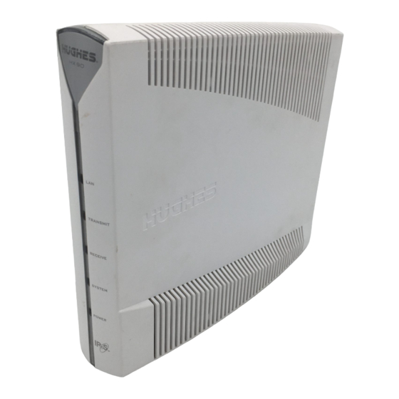
Router operating position NOTICE Install and operate the HX90 router only in the upright vertical position as shown in Figure 4. Any other position could result in insufficient ventilation, overheating, and malfunction. Figure 4: HX90 in vertical position Chapter 3 •... -
Page 23: Connecting The Transmit And Receive Cables
Connecting the transmit and receive cables Connect the transmit and receive IFL cables to the satellite router. 1. Connect the transmit and receive cables to the connectors on the rear panel of the router as shown in Figure 5. RESCUE SWITCH Router rear panel... -
Page 24: Connecting The Installer Laptop To The Router
Connecting the installer laptop to the router For this task you need an Ethernet cable. To access the satellite router so you can perform the required installation procedures, you connect your installer laptop computer to the router. After the router is installed and registered with the satellite network, you connect the router to the customer’s computer or other device. -
Page 25: Connecting An Ac/Dc Power Supply
Connecting an AC/DC power supply NOTICE The following apply to the AC/DC power supplies: • The input must be 120-240 VAC. • A suitable surge protector is recommended to protect the router from possible damage due to power surges. The customer provides the surge protector. If a surge protector or power strip is not present, use a wall outlet or other power source. -
Page 26: Connecting And Assembling A Dc/Dc Power Supply
AC power cord Figure 7: Connecting an AC power supply Connecting and assembling a DC/DC power supply Figure 8 shows the DC/DC power supply used with the HX90 router. Figure 8: DC/DC power supply Chapter 3 • Installing the satellite router... -
Page 27: Powering Up The Router
Connect and assemble the DC/DC power supply as follows: 1. Connect the DC power cord to the DC IN port on the router. Note: The input cable kit is included in the power supply kit. The cable kit contains an input power connector, connector pins, and a wiring diagram; it does not include wire. -
Page 28: Leds On Power-Up
LEDS on power-up As the router powers up, observe the front panel LEDs to make sure the router is working properly. When power is applied to the router or after a router reset, the LEDs light up in the following order, indicating normal power-up: 1. -
Page 29: Commissioning The Satellite Router
Commissioning methods Two methods are available for commissioning the HX90 satellite router: • Satellite-based commissioning on page 29 • Manual commissioning on page 57 Satellite-based commissioning is the preferred commissioning method. Use the manual commissioning method only if satellite-based commissioning is not available and if you are instructed to do so by the service provider. -
Page 30: Obtaining An Ip Address From The Satellite Router
Note: If the service provider has provided you with an file, you must sbc.cfg complete the procedures in Uploading the sbc.cfg file to the satellite router on page 32 to upload the file to the router. If you need troubleshooting information concerning satellite-based commissioning, see the satellite router’s online Help. - Page 31 If the ping fails, the ping results show that packets were lost, and time-out messages may also appear. Figure 10: Failed ping test 4. If the ping test fails, make sure: • The laptop’s network interface card (NIC) is properly installed. •...
-
Page 32: Uploading The Sbc.cfg File To The Satellite Router
Uploading the sbc.cfg file to the satellite router file contains satellite information for SBC and the auto-commissioning sbc.cfg server (ACS) to be used for the commissioning process. Once you have obtained the file, save it on the installer laptop computer making sure to note the sbc.cfg location where the file is saved. - Page 33 • On some screens and in some messages you may see the word terminal or the abbreviation VSAT. Both refer to the HX90 satellite router. • Screen and page are both used to refer to a set of information from your computer or satellite router that is displayed on your computer monitor.
-
Page 34: Entering Commissioning Parameters
Figure 13: Confirming the sbc.cfg file upload • After the upload completes, click Close on the Configuration File Upload screen to return to the Satellite Setup menu. Entering commissioning parameters To commission the satellite router you enter parameters for the antenna location, satellite, and radio. - Page 35 Figure 14: Satellite Setup menu 4. Click Registration - Installer 5. If you are installing the satellite router outside of the United States or Canada, go to Entering the antenna location (manual entry) on page 37. Follow the steps there to manually enter the antenna location. If you are installing the router in the United States or Canada, continue to the next step.
- Page 36 Figure 15: Antenna Location screen Next After you enter the ZIP code and click , the Verification of Antenna Location screen appears. Figure 16: Verification of Antenna Location screen Next 7. Verify that the displayed information is correct and click Chapter 4 •...
- Page 37 Entering the antenna location (manual entry) This is an alternate method for entering the antenna location. Use it only if you need to manually enter the antenna location. Use this method for router installations outside the United States or Canada. Skip this section if you have entered a ZIP code for the antenna location.
- Page 38 Figure 18: Satellite Parameters screen 2. From the list, select the satellite transponder listed on the Installation Reference Next Sheet or installation specification; then click Note: If your satellite transponder is not listed in the drop-down list, you must use the manual entry method. See Entering the antenna location (manual entry) on page 37.
- Page 39 The Verification of Satellite Parameters screen appears. Figure 19: Verifying the satellite parameters screen Next 3. Verify that the displayed information is correct and click Back If the parameters are not correct for the installation, click to change the satellite transponder selection. 4.
- Page 40 Next 2. Click Figure 20: Satellite Parameters screen The Manual Entry of Satellite Parameters screen appears. Figure 21: Manual Entry of Satellite Parameters screen 3. Enter or select the parameters. Chapter 4 • Commissioning the satellite router 1039456-0001 Revision A...
- Page 41 4. If you plan to use an antenna pointing tool, select DAPT, OPI, or N/A (for none) from the Antenna Pointing Tool drop-down list. For Ka-band select DAPT; for Ku-band a DAPT or OPI may be used. Next 5. Click Note: There is no verification screen when you manually enter the satellite parameters.
- Page 42 Figure 22: Receive LNB Selection screen—two variations Chapter 4 • Commissioning the satellite router 1039456-0001 Revision A...
- Page 43 Next 2. Click The Verification of Receive LNB Parameters screen appears, showing information for the selected LNB. Figure 23: Verification of Receive LNB Parameters screen Next 3. Verify that the displayed information is correct and click The Transmit Radio Parameters screen appears. Figure 24: Transmit Radio Parameters screen Chapter 4 •...
- Page 44 4. On the Transmit Radio Parameters screen, use the checkbox to select the radio part number if you know it—otherwise, select the transmit radio type (1 Watt or 2 Watt). The radio part number should be on the Installation Reference Sheet or installation specification.
-
Page 45: Receive Antenna Pointing - Ka-Band
Note: The list of transmit radio part numbers may be updated at any time, so you may see different part numbers than those shown in Figure 25 on page 44. Figure 26: Verification of Transmit Radio Parameters screen Next 6. Verify that the displayed information is correct and click The Receive Antenna Pointing screen opens. - Page 46 Display Signal Strength 1. On the Receive Antenna Pointing screen, click (Figure 27) to open the DAPT Antenna Pointing Status window. Figure 27: Receive Antenna Pointing screen Keep the Receive Antenna Pointing screen open until antenna pointing is complete. The Validate KA Antenna Pointing checkbox is checked by default. If you uncheck it (not recommended), pointing will not be validated.
- Page 47 Note: The DAPT Antenna Pointing Status window displays the DAPT test values as Close each pointing test is completed. If you click before antenna pointing is Display Signal done, the values will be lost. Then you would have to click Strength again on the Receive Antenna Pointing screen to reopen the DAPT Antenna Pointing Status window and begin pointing again.
- Page 48 Next 6. Click on the Receive Antenna Pointing screen. The KA Antenna Pointing Validation screen opens, showing a summary of the squinter pointing results. Figure 30: KA Antenna Pointing Validation screen — final validation passed Note: If you open the pointing validation screen before antenna pointing is complete, a message appears (instead of the text shown in the screen illustration above) asking you to wait until pointing is complete.
-
Page 49: Receive Antenna Pointing - Ku-Band
Receive antenna pointing — Ku-band Note: This section applies to Ku-band installations only. For Ka-band, skip this section; go to Registering the satellite router on page 52. Follow these steps to receive-point the antenna using the displayed signal strength, as shown in Figure 31. Adjust the antenna to point it as instructed in the antenna installation guide. -
Page 50: Transmit Antenna Pointing - Ku-Band
Transmit antenna pointing — Ku-band Note: This section applies to Ku-band installations only. 1. On the Receive Antenna Pointing screen, select the Perform ACP checkbox if your service provider offers automatic cross-polarization (ACP). Note: The Perform ACP checkbox is automatically checked if ACP is enabled at the NOC. - Page 51 4. In the Warning dialog that warns that the transmitter is actively powered on Continue during the manual cross-polarization test, click Figure 33: Manual cross-polarization warning message The Cross Pol Test window displays the test status, isolation value, and pass/fail result.
-
Page 52: Registering The Satellite Router
Registering the satellite router To register the satellite router with the service provider’s network, you select and access a registration server. To register the satellite router: Next 1. Click on the Transmit Antenna Pointing screen. 2. On the Registration Server Selection screen, select a registration server from the drop-down list. - Page 53 Next 3. Click The Registration in Progress screen appears, displaying registration status information. Figure 36: Registration in Progress screen Next 4. Click on the Registration in Progress screen when prompted to do so. 5. Click on the redirect notification message window (shown here) to access the registration server.
- Page 54 Registering in the United States or Canada (consumer installations) This section applies only to consumer installations in the United States or Canada. 1. Read the INSTALLER NOTICE! carefully. 2. Ask the customer to scroll down to review and accept the subscriber agreement. If the customer does not accept the agreement, you cannot continue with the Accept installation.
- Page 55 Registering outside the United States and Canada, and enterprise installations This section applies only to enterprise installations and all installations outside the United States and Canada. 1. Enter the customer’s site ID on the registration screen (Figure 40) and click Continue Figure 40: Entering a site ID 2.
- Page 56 Continue 1. On the Registration Welcome screen, click Figure 41: Registration Welcome screen The Registration screen appears. Figure 42: Registration screen with router identification information Chapter 4 • Commissioning the satellite router 1039456-0001 Revision A...
-
Page 57: Manual Commissioning
This screen shows the Site ID, the router’s IP address (Terminal IP Address), and the router’s subnet mask (Terminal Subnet Mask). Print this Page 2. If a printer is available, click to print the Registration screen. 3. Give the printout to the customer. The customer will need this information if they ever need to contact their service provider for assistance. -
Page 58: Entering Parameters-Manual Commissioning
keys and certain parameters to the router. Manual commissioning process consists • Entering manual commissioning parameters • Antenna pointing For both tasks you use the satellite router’s web-based interface. Note: The satellite router’s serial number must be loaded at the NOC by a NOC representative to complete the manual commissioning process. -
Page 59: Manually Accessing The Antenna Pointing Screens
VSAT Manual Commissioning 3. Click to access the Manual Commissioning page. Figure 45: Manual Commissioning page 4. Enter or select parameters on the Manual Commissioning page. The parameters may be provided to you in the Installation Reference Sheet, installation specification, or in another form of communication from your installation point-of-contact. -
Page 60: Software Download-Manual Commissioning
1. Open a web browser on the installer laptop. 2. Type in the http://192.168.0.1/fs/registration/ setup.html Enter browser address bar and press . The Satellite Setup menu opens (Figure 44 on page 58). Antenna Pointing 3. Click . The Antenna Pointing screen appears as shown in Figure 46 on page 60. -
Page 61: Completing The Installation
Chapter 5 Completing the installation This chapter describes the tasks you perform after commissioning to complete the satellite router installation. Confirming that the satellite router’s files are up to date Use the System Control Center to confirm that the satellite router is operating with the most current version of software. - Page 62 All files are up-to-date the router: a. Go to the System Control Center home page. Restart HX90 b. In the Help section, click 8. If you do not see the All files are up-to-date message, power cycle the satellite router: a.
-
Page 63: Connecting The Satellite Router To The Customer's Computer
Ethernet device Router rear panel Figure 48: Connecting the HX90 to the customer’s computer You (the installer) are required to stay at the installation site until the customer can connect to the Internet so you can offer assistance if necessary. -
Page 64: Creating A Shortcut To The System Control Center
Help the customer print a copy of the System Control Center’s System Information page, which contains important information about the status of the satellite router. Explain to the user that they will need the information on this page if they ever need technical assistance at a time when they cannot access the System Information page. - Page 65 Once the satellite router installation is complete, the customer can connect an Ethernet hub, router, or switch to the HX90 router to support multiple computers on a LAN, using the address information shown in on the System Information page (Figure 64 on page 82).
- Page 66 Chapter 5 • Completing the installation 1039456-0001 Revision A...
-
Page 67: System Control Center
Chapter 6 System control center The System Control Center is a set of screens and links you can use to monitor your broadband service and troubleshoot the satellite router in the event of a problem. The System Control Center provides access to system status, configuration information, and online documentation through a web browser on a computer connected to the satellite router. -
Page 68: Text Links
The button links at the top of the page appear on all System Control Center screens and are explained in Button links on page 70. Figure 50: System Control Center home page Text links The System Control Center home page includes the following text links: System Status links •... - Page 69 – Through this link you can find general operating instructions for the Getting Started HX90 router, recommended settings for your browser and TCP/IP, answers to frequently asked questions, and troubleshooting information. – Opens the Help page, which includes a variety of topics such as View Help Topics recommended browser and TCP/IP settings.
-
Page 70: Common Features On System Control Center Screens
Common features on System Control Center screens Certain features are common to some or all of the System Control Center screens, as shown in Figure 51. These features are explained in the following sections. Figure 51: Common features on System Control Center screens Button links At the top of each System Control Center page are four round buttons with labels above them as shown in Figure 52 on page 71. - Page 71 label. The System Status button link is also a status indicator, as explained in Table 5 on page 72. The other three button links are links only; they are not indicators. Figure 52: System Control Center button links The destination page for each button link is identified below: Table 4: Button links on System Control Center screens Button Destination...
- Page 72 see more detailed status information, click the System Status button to open the System Status page. Table 5: System Status button colors Button color Meaning The satellite router is operating normally. (OK Green appears beneath the System Status button.) A problem has been detected. Performance is temporarily impaired because: Yellow •...
-
Page 73: Links In The Left Panel
IPSec (Internet Protocol Security) is a set of network protocols and services that provide security to IP networks by authenticating and encrypting each IP packet of a data stream. IPSec-protected packets travel through a virtual tunnel or path between two points. An IPSec tunnel is up when it has been established between two peers and is capable of carrying traffic. -
Page 74: Status And Information Screens
Status and information screens Several of the System Control Center screens list status and operational parameters and their current values in a tabular format. For example, the following illustration shows the Reception Information page. The left column list the parameters, and the right column shows the current value of the parameter listed in the left column. -
Page 75: Features A Customer May Not See
flagged value appears in the right column; the parameter appears in the left column. The value indicates the current state of the parameter. Figure 56: Red flag problem indicator If you see a red flag, you can click the underlined parameter value in the right column to see additional information about the problem. -
Page 76: Parameter Explanation
Available system status values may vary, depending on how the satellite router is configured. Therefore, some options shown in Figure 57 may not appear on your System Status screen. Figure 57: System Status page The parameters listed on the System Status page are explained in the following table. -
Page 77: Reception Information Page
Table 6: System Status page parameters (Continued) Parameter Explanation TCP Acceleration Status Indicates if TCP Acceleration is operational or other status. TCP acceleration improves the router’s performance. Web Acceleration Status Indicates if Web Acceleration is operational or other status. Web acceleration improves web browsing performance. This field is present only if the NOC operator has enabled Web Acceleration on the satellite router. -
Page 78: Examining Receive Status
Level of encoding the router can accept based on the current signal quality. Lower Modcod numbers are used if signal impairments such as rain are present. Adaptive coding and modulation (Modcod) is a Hughes-developed technique that maximizes over-the-air bandwidth utilization. Examining receive status You can check the Receive Status parameter to find out if the receive data path is operational or if there is a problem. -
Page 79: Transmission Information Page
The next illustration shows the list of all RxCodes. Click the explanation (link) next to the RxCode to see more information. Figure 60: List of all RxCodes Transmission Information page The Transmission Information page shown in Figure 61 displays information about data transmissions from the satellite router. -
Page 80: Examining Transmit Status
The parameters listed on the Transmission Information page are explained in the following table. Table 8: Transmission Information page parameters Parameter Explanation Transmit Status Indicates if the transmit data path is operational. Click the displayed TxCode for explanation of the displayed code. Number of Successful Transmissions Number of frames transmitted to the satellite. - Page 81 The next illustration shows the list of all TxCodes. Click the explanation (link) next to the TxCode to see more information. Figure 63: List of TXCodes (not all codes are shown) Chapter 6 • System control center 1039456-0001 Revision A...
-
Page 82: System Information Page
Other sections of the screen (Transmit Radio Info and Satellite) provide additional information about the router installation and the router software (Software Configuration). Table 9: System Information page parameters — HX90 Info section Parameter Explanation Site ID Identifies the site where the router is installed. -
Page 83: Help Page
Table 9: System Information page parameters — HX90 Info section (Continued) Parameter Explanation Software Release Version of the router’s software. This is typically the factory-installed software version. However, if the NOC downloads a newer version of Gateway software to the router, the newer version number is displayed. -
Page 84: System Control Center Tools For Troubleshooting
• Click in the left panel of any System Control Center page. Help Figure 65: Help page System Control Center tools for troubleshooting The System Control Center includes screens that are useful for troubleshooting. For details see: • Troubleshooting common problems on page 91 •... -
Page 85: Leds
LEDs indicate the router’s operating status. All are blue when lit. The front panel LEDs are all blue when lit. Figure 66: Front panel LEDs on the HX90 router Chapter 7 • LEDs 1039456-0001 Revision A... - Page 86 Table 10 explains what the router status is when the LEDs are on, off, or blinking. On means the LED is continuously lit. Blinking means the LED is usually on, but intermittently turns off briefly. Flashing means the LED alternates between on and off for periods of ½...
-
Page 87: Lan Port Leds
LAN port LEDs Green and orange LEDs on the each of the two LAN (Ethernet) ports on the router’s rear panel indicate link status and speed, as explained in Figure 67. Figure 67: LAN port LEDs Using LEDs for troubleshooting For information on using the satellite router’s LEDs for troubleshooting, see: •... - Page 88 Chapter 7 • LEDs 1039456-0001 Revision A...
-
Page 89: Troubleshooting
• The Advanced Pages contain diagnostic and other information that may help in troubleshooting. See Chapter 9 – Advanced Pages on page 111. In addition, the HX90 satellite router provides its own online Help, which includes substantial troubleshooting information (including troubleshooting commissioning problems). -
Page 90: Troubleshooting Reference Diagram
If you need to use any of the troubleshooting procedures provided in this chapter, you may find it useful to refer to Figure 68. This diagram shows all power and cable connections for a properly installed HX90 satellite router. Figure 68: Troubleshooting reference diagram Chapter 8 •... -
Page 91: Troubleshooting Common Problems
If you have tried all of these procedures and cannot access the Internet, try them all again. If you still cannot access the Internet, contact Hughes Installer Support. For most of these troubleshooting procedures you use the router’s System Control Center. - Page 92 Note: The System Info page for your installation may show different fields and values. 2. In the HX90 section, check the Site ID line. If the numeric site ID appears, the satellite router is commissioned. Proceed to Confirming the receive signal on page 93.
-
Page 93: Confirming The Receive Signal
Confirming the receive signal To confirm that the router is properly receiving satellite signals: 1. At the System Control Center, click the link. Reception Info The Reception Information page appears. 2. In the Receive Status field, check the RxCode. If the RxCode is Receiver operational ( ) the router is receiving signals RxCode 5 properly;... -
Page 94: Confirming That Tcp Acceleration Is Operational
Figure 71: Transmission Info page Note: The TxCode shown is an example. Confirming that TCP Acceleration is operational TCP Acceleration is a proprietary Hughes protocol that optimizes performance for TCP/IP-based applications, including faster downloads over satellite. To determine if TCP acceleration is operational: 1. -
Page 95: Confirming That Web Acceleration Is Operational
Note: This section applies only if the NOC operator has enabled Web Acceleration on the satellite router. Web Acceleration is a Hughes feature that enhances browsing performance on non-secure web sites. Follow these steps to confirm that Web Acceleration is operating properly: 1. - Page 96 5. If Web acceleration is still disabled, restart the router: a. Go to the System Control Center home page. b. In the Help section, click Restart HX90 6. If Web acceleration is still disabled, power cycle the router: a. Unplug the power cord from the power source.
-
Page 97: Confirming Noc Connectivity
Confirming NOC connectivity Use the Connectivity Test page to check connectivity to the Hughes Network Operations Center (NOC). You may want to open a second web browser to access the Help page while you execute a connectivity test. 1. Click... -
Page 98: Confirming Noc Connectivity (Static Ip Address)
The default gateway address should be the router IP address as displayed on the System Information page HX90 Info section, in the LAN1 IP Address field. 1. Check the default gateway address in the computer operating system’s network properties settings;... -
Page 99: Confirming Internet Connectivity
d. Plug the power cord back into the power source. e. If the power source is DC, plug the input cable back into the power supply. CAUTION Do not power cycle the satellite router by unplugging the power cord from the router's rear panel. -
Page 100: Checking For Viruses And Firewall Issues
If you are using a firewall, refer to the firewall documentation and make sure none of its settings are blocking access to either the Internet or the Hughes servers. Make sure you are using the latest version of any anti-virus and/or firewall software. -
Page 101: Using The Front Panel Leds For Troubleshooting
This temporarily bypasses the Ethernet device as a way to help determine where and what the problem is. 3. Power cycle the satellite router: a. Unplug the power cord from the power source. b. If the router is connected to a DC power source, unplug the DC input cable from the satellite router’s power supply. -
Page 102: Power Led Off And One Or More Leds Flashing
Power LED off and one or more LEDs flashing If after power-up or a reset the Power LED is off and one or more of the other LEDs is flashing, the router could have a fatal error and may have to be replaced. If all LEDs are flashing, go to All LEDs flashing on page 102. -
Page 103: Checking The Power Led
d. Plug the power cord back into the power source. e. If the power source is DC, plug the input cable back into the power supply. CAUTION Do not power cycle the satellite router by unplugging the power cord from the router’s rear panel. -
Page 104: Problem With A Connected Device
If the front panel LAN LED is still off, check the Windows Device Manager to see if the computer’s NIC or network adapter is installed correctly. a. In Windows XP, for example, click Start > Settings > Control Panel > System > Hardware >... -
Page 105: Transmit Led Is Off
2. If the LED is still off, restart the router: a. Go to the System Control Center home page. b. In the Help section, click Restart HX90 3. If the LED is still off, power cycle the satellite router: a. Unplug the power cord from the power source. -
Page 106: System Led Is Off
d. Plug the power cord back into the power source. e. If the power source is DC, plug the input cable back into the power supply. CAUTION Do not power cycle the satellite router by unplugging the power cord from the router’s rear panel. -
Page 107: Orange Led And The Front Panel Lan Led Are Both Off
Orange LED and the front panel LAN LED are both off If both the orange LED and the front panel LAN LED are off: 1. Check all network equipment that connects the satellite router with the computer, including the computer's network card, network cable(s), and switch or hub if used. -
Page 108: Viewing Problem-Related Statistics
Viewing problem-related statistics Note: The Detailed Problem Statistics page and link are present on your HX90 only if they have been enabled by the NOC. You can use the Detailed Problem Statistics page to view selected operational statistics recorded over a recent specific hourly time frame. -
Page 109: Checking For Possible Ac Outlet Problems
2. From the drop-down list above the Get Statistics button, select a category of statistics (for example, TCP Acceleration). Figure 76: Selecting a category of statistics 3. Select a time period (for example, 0 - 1 hour ago). Get Statistics 4. - Page 110 Chapter 8 • Troubleshooting 1039456-0001 Revision A...
-
Page 111: Lnb Selection Reference
Appendix A LNB selection reference This appendix applies to the commissioning task of entering the radio parameters (Entering radio parameters on page 41). As part of this task you select the LNB for your installation from a drop-down list. If you are not sure which LNB to select on the Receive LNB Selection screen (Figure 22 on page 42), the illustrations in this appendix may help you identify the installed LNB and therefore which option you should select from the drop-down list. - Page 112 Figure 78: Selection aid for Ku-band LNBs Appendix A • LNB selection reference 1039456-0001 Revision A...
-
Page 113: Updating The Router Software
Hughes. The Fallback Updater is typically distributed to installers, when it is needed, as a file in an email message and may also be available for download from your .ZIP... - Page 114 Appendix B • Updating the router software 1039456-0001 Revision A...
-
Page 115: Standards Compliance
Appendix C Standards compliance The HX90 satellite router has been certified to comply with the standards listed in Table 11. Additional information follows the table. Table 11: HX90 standards compliance Category Standard Safety UL60950-1 for the USA CAN/CSA-C22.2 No. 60950-1 for Canada... -
Page 116: Electromagnetic Interference (Emi)
FCC Part 15 This section applies to the HX90 satellite router. Standards to which conformity is declared: FCC Part 15 The router complies with Part 15 of the FCC Rules. Operation is subject to the... -
Page 117: Canada Class B Warning
Canada Class B warning The two-way Hughes system (HX90) complies with the Canadian ICES-003, Class B standard. Cet appareil numérique de la classe B est conforme á la norme NMB-003 du Canada. R&TTE (EU) This product is within the scope of the EU Radio Equipment and Telecommunications Terminal Equipment (R&TTE) Directive. - Page 118 Appendix C • Standards compliance 1039456-0001 Revision A...
-
Page 119: Acronyms And Abbreviations
Acronyms and abbreviations ID – Identifier IDU – indoor unit AC – Alternating current IFL – Inter-facility link ACP – Automatic cross-polarization IP – Internet Protocol ACS – Auto-commissioning server IPoS – Internet Protocol over Satellite IPSec – Internet Protocol Security CAN –... - Page 120 SAN – Site account number SAT IN – Satellite in SAT OUT – Satellite out SBC – Satellite-based commissioning SQF – Signal quality factor TCP – Transmission Control Protocol TCP/IP – Transmission Control Protocol/Internet Protocol TIA – Telecommunications Industry Association UL –...
-
Page 121: Index
Index TCP Acceleration 94 transmit signal 93 AC/DC power supply 25 Web Acceleration 95 Address for opening the System Control Connecting 23 Center 67 IFL cables 23 Address, See IP address 10 installer laptop to satellite router 24 Advanced Pages satellite router to the customer’s accessing 73 computer 63... - Page 122 Icon for accessing Advanced Pages 73 Manual commissioning 57 IFL cable connectors 19 IFL cables connecting to router 23 Networking requirements 18 grounding 19 N-G voltage 14 requirements 19 measureing 14 specifications 20 N-G voltage, measuring 109 Installation checklist 13 Installation Reference Sheet, defined 11 Installation specification, defined 11 Installation summary 11...
- Page 123 RxCodes 78 Updating router software (fallback.bin file) 113 Uploading the sbc.cfg file 32 Safety standards, Canadian 115 Safety symbols 8 Satellite parameters 37 Ventilation 22 Satellite router overview 9 Viruses 100 Satellite transponders 37 Satellite-based commissioning 29 sbc.cfg file 32 Scope of this guide 10 Shortcut to the System Control Center 64 Site survey 15...
- Page 124 • Index 1039456-0001 Revision A...
Need help?
Do you have a question about the HX90 and is the answer not in the manual?
Questions and answers