FujiFilm SonoSite Edge II User Manual
Hide thumbs
Also See for SonoSite Edge II:
- User manual supplement (310 pages) ,
- Service manual (96 pages) ,
- User manual (88 pages)
Table of Contents
Advertisement
Quick Links
Advertisement
Table of Contents

Subscribe to Our Youtube Channel
Related Manuals for FujiFilm SonoSite Edge II


Summary of Contents for FujiFilm SonoSite Edge II
- Page 1 SonoSite Edge II USER GUIDE Ultrasound System User Guide...
- Page 2 SiteLink, SonoSite Edge, SonoHD2, SonoMB, Steep Needle Profiling, SonoSite, and the SonoSite logo are trademarks and registered trademarks of FUJIFILM SonoSite, Inc. in various jurisdictions. Value from Innovation is a trademark of FUJIFILM Holdings America Corporation. DICOM is a registered trademark of the National Electrical Manufacturers Association.
-
Page 3: Table Of Contents
1. Introduction Changes in version 1.2 ............................1-1 Document conventions ............................1-1 Getting help ................................1-2 2. Getting Started About the system ..............................2-1 License key ................................2-1 Intended uses ................................. 2-1 Hardware features ..............................2-4 Preparing the system ............................2-5 Installing or removing the battery ....................... - Page 4 Audio, Battery setup ............................3-8 Cardiac Calculations setup ..........................3-9 Connectivity setup ..............................3-9 Date and Time setup ............................3-10 Display Information setup ..........................3-10 Network Status setup ............................3-11 OB Calculations setup ............................3-11 OB Custom Measurements setup ......................3-12 OB Custom Tables setup ..........................
- Page 5 Doppler measurements ..........................5-5 General Calculations ............................. 5-7 Calculations menu ............................5-7 Performing and saving measurements in calculations ............. 5-8 Displaying, repeating, and deleting saved measurements ........... 5-8 EMED calculations ............................5-9 Percent reduction calculations ....................... 5-9 Volume calculation ............................ 5-11 Volume flow calculation .........................
- Page 6 Storing the transducer ............................. 8-11 Transporting the transducer .......................... 8-11 Cleaning the stand ............................. 8-13 Cleaning accessories ............................8-13 Cleaning and disinfecting the ECG cable and slave cable ........... 8-13 9. Safety Ergonomic safety ..............................9-1 Position the system ............................ 9-2 Position yourself ............................
- Page 7 Guidelines for reducing MI and TI ......................10-3 Output display ..............................10-7 MI and TI output display accuracy ....................10-9 Factors that contribute to display uncertainty ................10-9 Related guidance documents ......................10-9 Transducer surface temperature rise ..................... 10-10 Acoustic output measurement ......................... 10-11 In Situ, derated, and water value intensities ................
- Page 8 viii...
-
Page 9: Introduction
Introduction This SonoSite Edge II Ultrasound System User Guide provides information on preparing and using the SonoSite Edge II ultrasound system and on cleaning and disinfecting the system and transducers. It also provides system specifications, and safety and acoustic output information. -
Page 10: Getting Help
“Glossary” on page A-1. Getting help In addition to this user guide, the following resources are available: Instructional videos available on-line. FUJIFILM SonoSite Technical Support: 877-657-8118 Phone (U.S. or Canada) 425-951-1330, or call your local representative Phone (outside U.S. or Canada) 425-951-6700 fss-service@fujifilm.com... -
Page 11: Getting Started
USB device containing the software. One USB device can upgrade multiple systems. Intended uses The SonoSite Edge II ultrasound system is a general purpose ultrasound system intended for use by qualified physicians and healthcare professionals for evaluation by ultrasound imaging or fluid flow analysis of the human body. - Page 12 W ARNING To prevent misdiagnosis, do not use the ECG trace to diagnose cardiac rhythms. The FUJIFILM SonoSite ECG option is a non-diagnostic feature. Gynecology and infertility imaging applications You can assess the uterus, ovaries, adnexa, and surrounding anatomical structures for the presence or absence of pathology transabdominally or transvaginally.
- Page 13 During the first trimester, you should limit the duration of ultrasound imaging WARNINGS based on MI/TI. See Chapter 10, “Acoustic Output,” for more information. To prevent injury or misdiagnosis, do not use this system for fetal growth screening if the advanced OB calculations and reports package is not available. To prevent injury or misdiagnosis, do not use this system for Percutaneous Umbilical Blood Sampling (PUBS) or in vitro Fertilization (IVF) The system has not been validated to be proven effective for these two uses.
-
Page 14: Hardware Features
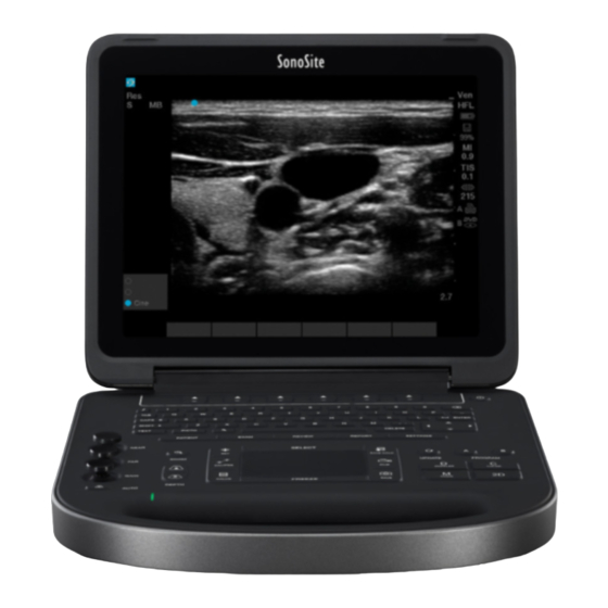
For the intended transducer and imaging modes for each exam type, see “Imaging modes and exams available by transducer” on page 4-15. Contraindications The SonoSite Edge II ultrasound system has no known contraindications. Hardware features Figure 2-1 Front of the SonoSite Edge II Ultrasound System... -
Page 15: Preparing The System
Figure 2-2 Back of the SonoSite Edge II Ultrasound System DC input I/O connector Battery ECG connector Basic operating steps 1 Attach a transducer. 2 Turn the system on. For power switch location, see “System controls” on page 2-12. 3 Press the PATIENT key, and complete the patient information form. - Page 16 3 Place the battery into the battery compartment, at a slight angle. 4 Slide the battery forward until it locks into place. 5 Slide the two locking levers outward to secure the battery. To remove the battery 1 Disconnect the power supply from the ultrasound system. 2 Remove the system from the mini-dock (if present) and turn it upside down.
-
Page 17: Using Ac Power And Charging The Battery
9-24. Plug the system only into a grounded hospital-grade outlet. Use only power cords provided by FUJIFILM SonoSite with the system. To operate the system using AC power 1 Connect the DC power cable from the power supply to the connector on the system. Refer to Figure 2-2 on page 2-5. -
Page 18: Turning The System On Or Off
Do not use the system if an error message appears on the image display: note the error code; call FUJIFILM SonoSite or your local representative; turn off the system by pressing and holding the power key until the system powers down. -
Page 19: Connecting Transducers
Connecting transducers WARNING To avoid injury to the patient, do not place the connector on the patient. Operate the ultrasound system in a docking system or on a flat hard surface to allow air flow past the connector. Caution To avoid damaging the transducer connector, do not allow foreign material in the connector. -
Page 20: Inserting And Removing Usb Storage Devices
5 Press the latch down, securing the transducer connector to the system. To remove a transducer 1 Pull the transducer latch up. 2 Rotate it clockwise. 3 Pull the transducer connector away from the system. Inserting and removing USB storage devices You can use a USB storage device to import and export various logs and setup configurations, and to archive images and clips. - Page 21 Caution If the USB icon does not appear in the system status area on-screen, the USB storage device may be defective or software-encrypted. Turn the system off and replace the device. To insert a USB storage device Insert the USB storage device into any USB port on the system or mini-dock. See Figure 2-1 page 2-4.
-
Page 22: System Controls
System controls NEAR SELECT SAVE CALC UPDATE PROGRAM ZOOM CALIPER CLIP DOPPLER COLOR GAIN MODE CALC SAVE FREEZE DEPTH AUTO Figure 2-3 Control panel Table 2-1: Keyboard map Control keys Adjust on-screen controls. Alphanumeric keys Enter text and numbers. Annotation keys “Annotation and text”... - Page 23 Table 2-1: Keyboard map (continued) AUTO Adjusts gain automatically. Magnifies the image 100%. ZOOM DEPTH UP, Decreases and increases imaging depth. DEPTH DOWN Sets a trace measurement. CALIPER Displays calipers on-screen for measuring. CALC Turns the calculations menu on and off. Touchpad Selects, adjusts, and moves items on-screen.
-
Page 24: Screen Layout
Table 2-1: Keyboard map (continued) Accesses the setup pages. SETTINGS PATIENT Accesses patient information. EXAM Opens exam menu. REVIEW Accesses the patient list, saved images, and archiving functions. REPORT Accesses the patient report and EMED worksheets. Power switch Turns system on and off. Screen layout Figure 2-4 Sample screen... -
Page 25: General Interaction
Table 2-2: Screen map (continued) Orientation Marker Indication for image orientation. Text Text entered using keyboard. Pictograph Pictograph to indicate anatomy and transducer position. You can select anatomy and screen location. Calculations Menu Contains available measurements. Image Ultrasound image. Measurement and Current data on measurements and calculations. -
Page 26: On-Screen Controls
On-screen controls The on-screen controls let you make adjustments and select settings. The controls available depend on context. Each control is controlled by the pair of keys below it. Depending on the control, the keys function in one of four ways: Cycle Moves through a list of settings continuously. -
Page 27: Annotation And Text
Annotation and text Figure 2-5 Alphanumeric keyboard Table 2-3: Alphanumeric keyboard map Moves cursor among fields in the forms, and tabs between text position in dual screens. CAPS lock Sets the keyboard to capital letters. SHIFT Allows entry of capitalized characters and international characters. TEXT Turns the keyboard on and off for text entry. - Page 28 Patient information form: Last, First, Middle Patient ID Accession Indications Procedure ID User Reading Dr. Referring Dr. Institution fields DICOM or SiteLink configuration page: Alias and AE Title fields A & B Key, Footswitch setup page: Text field Text mode (imaging): Annotation field Figure 2-6 Symbols Dialog Box...
-
Page 29: Preparing The Transducers
Some gels and disinfectants can cause an allergic reaction in some individuals. To avoid damage to the transducer, use only gels recommended by FUJIFILM Cautions SonoSite. Using gels other than the one recommended by FUJIFILM SonoSite can damage the transducer and void the warranty. - Page 30 5 Check for and eliminate bubbles between the face of the transducer and the sheath. Bubbles between the face of the transducer and the sheath may affect the ultrasound image. 6 Inspect the sheath to ensure that there are no holes or tears. 2-20 Getting Started...
-
Page 31: System Setup
System Setup The setup pages let you customize the system and set preferences. Displaying the setup pages To display a setup page 1 Press the Settings key. 2 Select the setup page under Setup Pages. 3 To return to imaging from a setup page, select Done on-screen. Restoring default settings To restore default settings for a setup page ... -
Page 32: Administration Setup
“To connect the footswitch” on page 3-2. To connect the footswitch The FUJIFILM SonoSite footswitch allows hands-free operation with a customizable two-pedal footswitch. The footswitch is an optional feature. WARNING To avoid contamination, do not use the footswitch in a sterile environment. The footswitch is not sterilized. - Page 33 2 Type the administrator password in the Password box. If you don’t have the administrator password, contact FUJIFILM SonoSite. Refer to “Getting help” page 1-2. WARNING Restoring an administrative password will result in the deletion of data. Back up all data prior to resetting the administrative password.
-
Page 34: User Setup
2 Select Disable USB Export. User setup To add a new user 1 Log in as Administrator. 2 Select New. 3 Under User Information, fill in the Name, Password, and Confirm boxes. For more information about passwords, see “Choosing a secure password” on page 3-6. -
Page 35: Exporting Or Importing User Accounts
Exporting or importing user accounts The export and import commands let you configure multiple systems and back up user account information. To export user accounts 1 Insert a USB storage device. For more information, see “Inserting and removing USB storage devices” on page 2-10. -
Page 36: Logging In As User
2 Select Log and then select Export on-screen. A list of USB devices appears. 3 Select the USB storage device, and select Export. Note The Event log is a text file that you can open in a text-editing application (for example, Microsoft Word or Notepad). -
Page 37: Annotations Setup
Annotations setup On the Annotations setup page, you can customize predefined labels and set the preference for managing text when unfreezing images. For instructions to annotate images, refer to “Annotating images” on page 4-23. To predefine a label group You can specify which labels are available for an exam type when annotating an image. Refer to “To place text on an image”... -
Page 38: Audio, Battery Setup
To import predefined label groups 1 Insert the USB storage device that contains the label groups. 2 On the Annotations setup page, select Import. 3 Select the USB storage device, and then select Import. 4 Select Done in the dialog box that appears. All predefined label groups for all exams are replaced with those from the USB storage device. -
Page 39: Cardiac Calculations Setup
Cardiac Calculations setup On the Cardiac Calculations setup page, you can specify measurement names that appear in the Tissue Doppler Imaging (TDI) calculations menu and on the report page. See “Cardiac calculations” page 5-15. To specify cardiac measurement names Under TDI Walls on the Cardiac Calculations setup page, select a name for each wall. -
Page 40: Date And Time Setup
Date and Time setup On the Date and Time setup page, you can set up the date and time and enable synchronization with a clock on a server (Time Server). WARNING To obtain accurate obstetrics calculations, an accurate date and time are critical. Verify that the date and time are accurate before each use of the system. -
Page 41: Network Status Setup
Network Status setup The Network Status setup page displays information on system IP address, Location, Ethernet MAC address, and the wireless connection if any. OB Calculations setup WARNING To prevent injury or misdiagnosis, do not use this system for fetal growth screening if the advanced OB calculations and reports package is not available. -
Page 42: Ob Custom Measurements Setup
OB Custom Measurements setup On the OB Custom Measurements setup page, you can define measurements that appear in the OB calculations menu and OB report. OB Custom Measurements is an optional feature. See “OB calculations” on page 5-30. WARNING When you create, remove, or import a custom obstetric measurement, the system clears all saved measurements and calculations for the current patient. - Page 43 Gestational Age Table Measurements The system provides gestational age measurements by selected authors for the following: GS CRL BPD OFD HC TTD APTD AC FTA FL EFW Tibia HL Five additional custom measurement labels Growth Analysis Table Measurements The system provides growth graphs or curves for the following: BPD HC AC...
-
Page 44: Presets Setup
5 In the Author box, type a unique name. 6 Enter the data. 7 Select Save on-screen. To display the measurement for the custom table in the calculations menu, see “To specify gestational age and growth analysis” on page 3-11. To edit or delete an OB custom table 1 On the OB Calculations or OB Custom Measurements setup page, select Tables on-screen. -
Page 45: System Information Setup
Thermal Index Choose between TIS, TIB, or TIC. By default, this setting is based on exam type: OB is TIB, TCD is TIC, and all others are TIS. Save Key Determines the behavior of the Save key: Image Only Saves the image to internal storage. -
Page 46: Usb Devices Setup
1 On the USB Devices setup page, select Export. 2 Under USB Export select the AutoExport box. To include private tags 1 If you use DICOM export type and a FUJIFILM SonoSite software product, include private tags on the images. 3-16... -
Page 47: Limitations Of Jpeg Format
2 On the USB Devices setup page, select Include private tags. Note Because the tags may be incompatible with some earlier archivers, keep this check box unselected unless you use FUJIFILM SonoSite software products. For more information, refer to the ultrasound system’s DICOM conformance statement. Limitations of JPEG format When transferring or exporting images in JPEG format, the system uses lossy compression. - Page 48 3-18 System Setup...
-
Page 49: 2D Imaging
Imaging Imaging modes The SonoSite Edge II system has a high-performance display and advanced image-optimization technology that simplifies user controls. Available imaging modes depend on the transducer and exam type. Refer to “Imaging modes and exams available by transducer” on page 4-14. - Page 50 2D controls Table 4-1: 2D on-screen controls Control Description Optimize Settings are as follows: Res provides the best possible resolution. Gen provides a balance between resolution and penetration. Pen provides the best possible penetration. Some of the parameters optimized to provide the best image include focal zones, aperture size, frequency (center and bandwidth), and waveform.
- Page 51 SNP depends on transducer and exam type. Displays the ECG trace. Refer to “ECG” on page 4-33. This feature is optional and requires a FUJIFILM SonoSite ECG cable. Clips Displays the clip controls. Refer to “To save a clip” on page 4-28.
-
Page 52: M Mode Imaging
M Mode imaging Motion mode (M Mode) is an extension of 2D. It provides a trace of the 2D image displayed over time. A single beam of ultrasound is transmitted, and reflected signals are displayed as dots of varying intensities, which create lines across the screen. - Page 53 To display the CPD or Color image 1 Press the C key. A ROI box appears in the center of the 2D image. The current selection (Color or CPD) appears in the upper left-hand screen. Note In Color imaging, the Color indicator bar on the upper left-hand screen displays velocity in cm/s.
-
Page 54: Pw And Cw Doppler Imaging
Table 4-2: CPD and Color on-screen controls Control Description Wall Filter Settings include Low, Med, and High. Steering Select the steering angle setting of the color ROI box (-15, 0, or +15). If adding PW Doppler, see “PW Doppler controls” on page 4-7. - Page 55 2 Do any of the following as needed: Adjust controls as described in “PW Doppler controls” on page 4-7. Using the touchpad, position the D-line and gate where desired. Horizontal movements position the D-line. Vertical movements position the gate. PW Doppler To correct the angle manually, do one of the following: Press the SELECT key and then use the touchpad.
- Page 56 Table 4-3: PW Doppler on-screen controls (continued) Control Description TDI On, Select TDI On to turn on Tissue Doppler Imaging. When on, TDI appears in the upper TDI Off left-hand screen. The default is TDI off. Available only in cardiac exams. Steering Select the desired steering angle setting.
-
Page 57: Adjusting Depth And Gain
Table 4-4: Spectral trace on-screen controls (continued) Control Description Wall Filter Settings include Low, Med, High. Sweep Settings include Slow, Med, Fast. Speed Live Trace Displays a live trace of the peak or mean. See “Presets setup” on page 3-14 to specify peak or mean. -
Page 58: Freezing, Viewing Frames, And Zooming
Freezing, viewing frames, and zooming To freeze or unfreeze an image Press the Freeze key. On a frozen image, the cine icon and frame number appear in the system status area. To move forward or backward in the cine buffer ... -
Page 59: Visualizing Needles
Visualizing needles WARNING To avoid incorrect needle placement when Steep Needle Profiling (SNP) is on: Use only FUJIFILM SonoSite or CIVCO approved needle guides, brackets, supplies, components, and accessories. Other brands may not properly fit FUJIFILM SonoSite transducers. Use only needle guides compatible with the transducers listed in Table 4-5, “Transducers and exam types available with SNP”... - Page 60 Table 4-5: Transducers and exam types available with SNP (continued) Transducer Arterial Breast Musculoskeletal Nerve Small Parts Venous HFL50x HSL25x L25x standard/armored L38xi standard/armored Outlined area enhanced by SNP Dotted line Needle shaft Unenhanced area Figure 4-7 Image with SNP on (linear transducer) Upper needle shaft Segment of needle shaft not shown...
-
Page 61: Needle Size And Angle
Needle size and angle Use a 17-gauge to 25-gauge needle (recommended). Enhancement results can depend on the type and brand of needle used. For more information, consult the medical literature on needle visibility in ultrasound-guided procedures. You can angle the needle up to 50° from the transducer surface as shown in Figure 4-9 on page 4-12. -
Page 62: Additional Recommendations
Back returns to the previous screen. If Steep Needle Profiling technology is on, SNP is highlighted and SNP appears in the mode data area. Pressing SNP again redisplays the SNP controls. Note If Steep Needle Profiling technology is on, the MB control is unavailable. Additional recommendations Avoid setting the gain too high when using Steep Needle Profiling technology, as unnecessarily high gain can cause artifacts in the image. -
Page 63: Imaging Modes And Exams Available By Transducer
Small tilts or rotations of the transducer can affect the relationship between any external reference points and the anatomy that appears on the ultrasound image. Figure 4-11 Relationship of the ultrasound image to the transducer angle or tilt. Imaging modes and exams available by transducer To prevent misdiagnosis or harm to the patient, understand your system’s WARNING capabilities prior to use. - Page 64 “PW Doppler controls” on page 4-7. Needle guide-capable. For more information, refer to Using CIVCO Products with FUJIFILM SonoSite Systems. For more information refer to the P11x Transducer User Guide, included with the P11x transducer. The P11x transducer is not licensed for use in Canada.
- Page 65 “PW Doppler controls” on page 4-7. Needle guide-capable. For more information, refer to Using CIVCO Products with FUJIFILM SonoSite Systems. For more information refer to the P11x Transducer User Guide, included with the P11x transducer. The P11x transducer is not licensed for use in Canada.
- Page 66 “PW Doppler controls” on page 4-7. Needle guide-capable. For more information, refer to Using CIVCO Products with FUJIFILM SonoSite Systems. For more information refer to the P11x Transducer User Guide, included with the P11x transducer. The P11x transducer is not licensed for use in Canada.
- Page 67 “PW Doppler controls” on page 4-7. Needle guide-capable. For more information, refer to Using CIVCO Products with FUJIFILM SonoSite Systems. For more information refer to the P11x Transducer User Guide, included with the P11x transducer. The P11x transducer is not licensed for use in Canada.
- Page 68 “PW Doppler controls” on page 4-7. Needle guide-capable. For more information, refer to Using CIVCO Products with FUJIFILM SonoSite Systems. For more information refer to the P11x Transducer User Guide, included with the P11x transducer. The P11x transducer is not licensed for use in Canada.
- Page 69 “PW Doppler controls” on page 4-7. Needle guide-capable. For more information, refer to Using CIVCO Products with FUJIFILM SonoSite Systems. For more information refer to the P11x Transducer User Guide, included with the P11x transducer. The P11x transducer is not licensed for use in Canada.
- Page 70 “PW Doppler controls” on page 4-7. Needle guide-capable. For more information, refer to Using CIVCO Products with FUJIFILM SonoSite Systems. For more information refer to the P11x Transducer User Guide, included with the P11x transducer. The P11x transducer is not licensed for use in Canada.
-
Page 71: Annotating Images
“PW Doppler controls” on page 4-7. Needle guide-capable. For more information, refer to Using CIVCO Products with FUJIFILM SonoSite Systems. For more information refer to the P11x Transducer User Guide, included with the P11x transducer. The P11x transducer is not licensed for use in Canada. - Page 72 To place text on an image You can place text manually or add a predefined label. 1 Press the TEXT key. A highlighted cursor appears. 2 Move the cursor where desired: Use the touchpad or arrow keys. Select Home to move the cursor to the home position. The default home position depends on the imaging screen layout.
-
Page 73: Patient Information Form
5 To remove the arrow, press the arrow key and then select Hide. To place a pictograph on an image The pictograph set available depends on transducer and exam type. 1 Press the PICTO key. 2 Select x/x to display the desired pictograph, and then press the SELECT key. The first number shows which pictograph in the set is selected. - Page 74 2 Select New/End. A new patient information form appears. 3 Fill in the form fields. For more information, see “Patient information form fields” on page 4-26. 4 Select Done. See also “To append images and clips to a patient exam” on page 4-30.
-
Page 75: Patient Information Form Fields
Patient information form fields The patient information form fields available depend on exam type. In some fields you can select Symbols to enter symbols and special characters. See “Symbols” on page 2-17 . Patient Last, First, Middle Patient name ID Patient identification number Accession Enter number, if applicable... -
Page 76: Images And Clips
Previous Exams (button) (OB exam). Displays fields for five previous exams. The date for a previous exam must precede the current system date. For twins, select Twin A/B to toggle between Twin A and Twin B screens. Note If the Twin A/B control does not appear, select Back, and make sure that the Twins check box is selected. - Page 77 The percentage icon shows the percentage of space available in internal storage. For information on receiving alerts when storage is near capacity, see “To receive storage alerts” on page 3-9. To access saved images and clips Open the patient list. For more information, see “Reviewing patient exams”...
-
Page 78: Reviewing Patient Exams
Reviewing patient exams Caution If the internal storage icon does not appear in the system status area, internal storage may be defective. Contact FUJIFILM SonoSite Technical Support. See “Getting help” on page 1-2. The patient list organizes saved images and clips in patient exams. You can delete, view, print, or archive exams. - Page 79 Using the touchpad, select the check box for one or more patient exams. Use Select All to select all patient exams. To deselect patient exams Do one of the following: Clear checked boxes. Select Clear All. To edit patient information from the patient list You can edit the patient name and ID from the patient list instead of from the patient information form if the exam is closed but has not been exported or archived.
-
Page 80: Printing, Exporting, And Deleting Images And Clips
5 Select x/x to cycle to the next image or clip you want to view. 6 To return to the patient list, select List. 7 To return to imaging, select Done. Printing, exporting, and deleting images and clips Caution To avoid damaging the USB storage device and losing patient data from it, observe the following: Do not remove the USB storage device or turn off the ultrasound system while the system is exporting. - Page 81 Exporting large amounts of data can take as long as a few hours depending on compression, file type, file size, and number of files. To avoid this issue, export data frequently—for example, after each patient exam or at the end of each day. Note You can export patient exams only if they have ended.
-
Page 82: Ecg
To avoid electrical interference with aircraft systems, do not use the ECG cable on aircraft. Such interference may have safety consequences. Use only accessories recommended by FUJIFILM SonoSite with the system. Cautions Connecting an accessory not recommended by FUJIFILM SonoSite can damage the system. -
Page 83: Ecg Controls
ECG controls Table 4-8: ECG on-screen controls Control Description Show/Hide Turns on and off ECG trace. Gain Increases or decreases ECG gain. Settings are 0-20. Position Sets the position of the ECG trace. Sweep Settings are Slow, Med, and Fast. Speed Delay Displays Line and Save for clip acquisition delay. - Page 84 4-36 Imaging...
-
Page 85: Measurements And Calculations
Measurements and Calculations You can measure for quick reference, or you can measure within a calculation. You can perform general calculations as well as calculations specific to an exam type. Measurements are performed on frozen images. For references used, see Chapter 6, “Measurement references.”... -
Page 86: Saving Measurements
To switch the active calipers Some measurements use two calipers. Only one caliper can be repositioned at a time. Use this procedure to toggle between the two calipers. The active caliper is highlighted. Do one of the following: To switch the active caliper within a set, press the SELECT key. To switch the active set when measuring outside a calculation, select Switch on-screen. -
Page 87: 2D Measurements
2D measurements The basic measurements that you can perform in 2D imaging are as follows: Distance in cm Area in cm Circumference in cm You can also measure area or circumference by tracing manually. You can perform a combination of distance, area, and circumference measurements at one time. The total number possible depends on their order and type. -
Page 88: M Mode Measurements
2 Select Manual on-screen. Note If you exceed the allowed number of measurements, Manual is not available. 3 Using the touchpad, position the caliper where you want to begin. 4 Press the SELECT key. 5 Using the touchpad, complete the trace, and press the SET key. To make a correction, select Undo on-screen, backtrack with the touchpad, or press the backspace key. -
Page 89: Doppler Measurements
6 See “To save a measurement to a calculation and patient report” on page 5-2. Note Saving the heart rate measurement to the patient report overwrites any heart rate entered on the patient information form. See also “To measure Fetal Heart Rate” on page 5-34. - Page 90 To measure time duration 1 On a frozen Doppler spectral trace, press the CALIPER key. 2 Select Time on-screen. A vertical caliper appears. 3 Using the touchpad, position the caliper where desired. 4 Press the SELECT key. A second caliper appears. 5 Using the touchpad, position the second caliper where desired, and press the SELECT key.
-
Page 91: General Calculations
Automatic trace results Depending on the exam type, the results from automatic tracing include the following: Velocity Time Integral (VTI) Cardiac Output (CO) Peak Velocity (Vmax) Peak Systolic Velocity (PSV) Mean Pressure Gradient (PGmean) Time Average Mean (TAM) Mean Velocity on Peak Trace (Vmean) +/×... -
Page 92: Performing And Saving Measurements In Calculations
To select from the calculations menu 1 On a frozen image, press the CALCS key. The calculations menu appears. 2 Using the touchpad or arrow keys, highlight the desired measurement name. Press the SELECT key. a To display additional measurement names, highlight Next, Prev, or a measurement name that has ellipses (. -
Page 93: Emed Calculations
3 Perform the measurement again. The new results appear on-screen in the measurement and calculations data area. See “Screen layout” on page 2-14. You can compare them to the saved results below the menu. 4 To save the new measurement, press the SAVE CALC key. The new measurement saves to the patient report and overwrites the previously saved measurement. - Page 94 For a list of exam types on each transducer, see “Imaging modes and exams available by transducer” on page 4-15. To calculate percent area reduction The percent area reduction calculation involves two manual trace measurements. 1 On a frozen 2D image, press the CALCS key. 2 Do the following for A and then for A a From the calculations menu, select the measurement name under Area Red.
-
Page 95: Volume Calculation
Volume calculation To avoid incorrect calculations, verify that the patient information, date, and time WARNINGS settings are accurate. To avoid misdiagnosis or harming the patient outcome, start a new patient form before starting a new patient exam and performing calculations. Starting a new patient form clears the previous patient’s data. - Page 96 Both a 2D and a Doppler measurement are required for the volume flow calculation: Table 5-1: Required measurements Measurement name (Imaging Calculation list Calculation result Mode) Volume Flow D (2D)*, TAM or TAP (Doppler) Vol Flow (Volume Flow ml/min) *Required if measuring the diameter instead of using the gate size For the 2D measurement, you can do either of the following: Measure the diameter of the vessel.
-
Page 97: Exam-Based Calculations
To calculate volume flow 1 If measuring the diameter instead of using the gate size, perform the 2D measurement: a On a frozen full-screen 2D image or duplex image, press the CALCS key. b From the calculations menu, select D (distance) under Vol Flow. c Position the calipers. - Page 98 Table 5-2: Arterial calculations Calculation list Measurement name Results Prox (Proximal) s (systolic), d (diastolic) Mid (Middle) Dist (Distal) Bulb Prox (Proximal) s (systolic), d (diastolic) Mid (Middle) Dist (Distal) Prox (Proximal) s (systolic), d (diastolic) Mid (Middle) Dist (Distal) VArty Trace only a single heartbeat.
-
Page 99: Cardiac Calculations
Cardiac calculations To avoid incorrect calculations, verify that the patient information, date, and time W ARNINGS settings are accurate. To avoid misdiagnosis or harming the patient outcome, start a new patient information form before starting a new patient exam and performing calculations. Starting a new patient information form clears the previous patient’s data. - Page 100 The following table shows the measurements required to complete different cardiac calculations. Not all calculations are listed. For definitions of acronyms, refer to “Glossary” on page A-1. Table 5-3: Cardiac calculations and results Calculation list Measurement name (imaging mode) Results LVDd (2D or M Mode) LVDFS LVDs (2D or M Mode)
- Page 101 Table 5-3: Cardiac calculations and results Calculation list Measurement name (imaging mode) Results LVOT D (2D) HR (Doppler) LVOT VTI (Doppler) LVOT D Ao (2D or M Mode) Ao/LA LA/Ao AAo (2D) LA (2D or M Mode) LA/Ao LVOT D (2D) LVOT D LVOT area ACS (M Mode)
- Page 102 Table 5-3: Cardiac calculations and results Calculation list Measurement name (imaging mode) Results E (Doppler) E PG A (Doppler) A PG PHT (Doppler) Decel time VTI (Doppler) Vmax PGmax Vmean PGmean IVRT (Doppler) time Adur (Doppler) time dP:dT dP:dT (CW Doppler) MV (2D) Area MV Area...
- Page 103 Table 5-3: Cardiac calculations and results Calculation list Measurement name (imaging mode) Results Epi (2D) LV mass LV Mass Epi Area Endo (2D) Endo Area Apical (2D) D Apical Vmax (Doppler) Vmax PGmax VTI (Doppler) Vmax PGmax Vmean PGmean LVOT Vmax (Doppler) Vmax PGmax...
- Page 104 Table 5-3: Cardiac calculations and results Calculation list Measurement name (imaging mode) Results RVSP RA pressure TR Vmax (Doppler) Vmax PGmax E (Doppler) E PG A (Doppler) A PG PHT (Doppler) Decel time VTI (Doppler) Vmax PGmax Vmean PGmean Vmax (Doppler) Vmax PGmax PV VTI (Doppler)
- Page 105 Table 5-3: Cardiac calculations and results Calculation list Measurement name (imaging mode) Results Radius (Color) PISA PISA Area MR VTI (Doppler) MV Rate Ann D (2D) Regurgitant Volume MV VTI (Doppler) Regurgitant Fraction LVOT D (2D) Qp/Qs RVOT D (2D) Vmax LVOT VTI (Doppler) PGmax...
- Page 106 c Save the calculation as described in “To save a calculation” on page 5-8. To calculate Atrial areas and volumes 1 On a frozen 2D image, press the CALCS key. 2 In the calculations menu, locate Atria, and then select the measurement name. 3 Position the caliper at the annulus, and press the SELECT key.
- Page 107 6 Position the caliper, and press the SELECT key. Repeat for each measurement name in the calculation group. Note Each time you press the SELECT key, another caliper appears, and the calculations menu highlights the next measurement name. 7 Save the calculation as described in “To save a calculation”...
- Page 108 3 Do the following for EPI and then for Endo: a Select the measurement name from the calculations menu. b Position the caliper where you want to begin the trace, and press the SELECT key. c Using the touchpad, trace the desired area. To make a correction, select Undo on-screen or press the backspace key.
- Page 109 e Save the calculation. For information on the automatic trace tool, refer to “To trace automatically in Doppler” on page 5-6. To calculate Tricuspid Annular Plane Systolic Excursion (TAPSE) 1 On a frozen M Mode trace, press the CALCS key. 2 From the calculations menu, select the measurement name.
- Page 110 4 Save the calculation as described in “To save a calculation” on page 5-8. Note: This calculation requires the RA pressure. If RA pressure has not been adjusted, the default value of 5 mmHg is used. To adjust the RA pressure, see “To modify the ICA/CCA ratio (Arterial)”...
- Page 111 1 In 2D, measure from LVOT: a On a frozen 2D image, press the CALCS key. b From the calculations menu, select LVOT D. c Position the calipers. d Save the calculation as described in “To save a calculation” on page 5-8. 2 In Doppler, measure LVOT Vmax, and then measure AV Vmax.
- Page 112 b From the calculations menu select Ao/LA then LVOT D. c Position the calipers. d Save the calculation as described in “To save a calculation” on page 5-8. 3 Measure from LVOT (Doppler). Refer to “To calculate Velocity Time Integral (VTI)” on page 5-25.
-
Page 113: Gynecology (Gyn) Calculations
b Select Trace on-screen, and then select Above or Below for the position of the automatic trace tool relative to the baseline. The automatic trace tool appears in yellow. Notes The results appear at the bottom of the screen. c Freeze the image. If you want to change the waveform measured, move each vertical caliper by pressing SELECT and then using the touchpad. -
Page 114: Ob Calculations
c Save the calculation as described in “To save a calculation” on page 5-8. To measure follicles On each side, you can save up to three distance measurements on a follicle, for up to 10 follicles. If you measure a follicle twice, the average appears in the report. If you measure a follicle three times, the average and a volume calculation appear in the report. - Page 115 If you change the calculation author during the exam, the common measurements are retained. Table 5-4: OB calculations for system-defined measurements Gestational OB Calculation Result Table Authors Measurements — Gestational Age Hansmann, Nyberg, Tokyo U. Hadlock, Hansmann, Osaka, Tokyo U. Chitty, Hadlock, Hansmann, Osaka, Tokyo U.
- Page 116 Table 5-4: OB calculations for system-defined measurements Gestational OB Calculation Result Table Authors Measurements Estimated Fetal Weight HC, AC, FL Hadlock 1 (EFW) BPD, AC, FL Hadlock 2 AC, FL Hadlock 3 Hansmann BPD, FL Osaka U. BPD, AC Shepard BPD, TTD, APTD, Tokyo U.
- Page 117 Table 5-4: OB calculations for system-defined measurements Gestational OB Calculation Result Table Authors Measurements Growth Analysis Chitty, Hadlock, Jeanty Tables Chitty, Hadlock, Jeanty Chitty, Hadlock, Jeanty Chitty, Hadlock, Jeanty Brenner, Hadlock, Jeanty HC/AC Campbell The Gestational Age is automatically calculated and displayed next to the OB measurement you selected. The average of the results is the AUA.
- Page 118 b For twins, select Twin A or Twin B, and then select the measurement name. Note The caliper tool may change depending on the measurement selected, but the position remains constant. c Position the calipers. d Save the calculation as described in “To save a calculation”...
-
Page 119: Small Parts And Msk Calculations
Required measurements for MCA or UmbA Table 5-5: MCA or UmbA calculations and results Calculation list Measurement name Results S/D, RI MCA (Middle Cerebral SD, RI Artery) S/D, RI, PI* SD, RI, PI, MDV S/D, RI Umb A (Umbilical Artery) SD, RI S/D, RI, PI* SD, RI, PI, MDV... -
Page 120: Transcranial Doppler And Orbital Calculations
3 Under d:D Ratio, select Fem Hd (femoral head). 4 Using the touchpad, position and resize the circle. The SELECT key toggles between position and size. Press the SET key. The baseline automatically appears with the left caliper active. 5 Position the caliper. See “Working with calipers”... - Page 121 Table 5-6: Transcranial Doppler and Orbital calculations and results (continued) Calculation list Measurements Results OA Siphon Gate Size ECICA Gate Size Prox Mid Dist Gate Size ECVA Gate Size *Available but not required. To perform a Transcranial Doppler or Orbital calculation 1 Select the Orbital or Transcranial exam type.
-
Page 122: Patient Reports And Worksheets
2 On a frozen Doppler spectral trace, press the CALCS key. 3 On a frozen Doppler spectral trace, press the CALCS key. 4 From the calculations menu, select Left or Right. 5 Do the following for each measurement you want to take: a From the calculations menu, select the measurement. -
Page 123: Arterial And Cardiac Patient Reports
Arterial and cardiac patient reports To delete an arterial or cardiac measurement 1 On the Details page of the patient report, select the measurement by using the touchpad. The selected measurement is highlighted. 2 Select Delete on-screen. Note Deleting some measurements also deletes related measurements. Deleted measurements are not included in the summary information. -
Page 124: Tcd Patient Report
To complete the OB biophysical profile On page 2 of the OB patient report, select values under BPP. The total is calculated when values are selected. NST (non-stress test) is optional. To display OB graphs You can display OB graphs if the LMP or Estab. DD fields are complete in the patient information form. 1 On the OB patient report, select Graphs on-screen. - Page 125 To display an MSK worksheet 1 During or after the exam, press the REPORT key. 2 Select MSK on-screen. 3 Select the worksheet from the Worksheet list or by selecting x/x on-screen. a To display additional pages in the worksheet, select x/x on-screen.
- Page 126 5-42 Measurements and Calculations...
-
Page 127: Measurement References
Measurement references This section provides information about measurement accuracy, publications, and terminology. Measurement accuracy The measurements from the system are of a physical property such as distance for evaluation by the clinician. The accuracy values require that you can place the calipers over one pixel. - Page 128 Full scale for distance implies the maximum depth of the image. An RMI 413a model phantom with 0.7 dB/cm MHz attenuation was used. Full scale for time implies the total time displayed on the scrolling graphic image. FUJIFILM SonoSite special test equipment was used. Measurement references...
-
Page 129: Sources Of Measurement Errors
An RMI 413a model phantom with 0.7 dB/cm MHz attenuation was used. Full scale for time implies the total time displayed on the scrolling graphic image. FUJIFILM SonoSite special test equipment was used. Table 6-3: PW Doppler Mode Measurement and Calculation Accuracy and Range... -
Page 130: Measurement Publications And Terminology
Measurement publications and terminology The following are the publications and terminology used for each calculation result. Terminology and measurements comply with American Institute of Ultrasound in Medicine (AIUM) published standards. Cardiac references Acceleration (ACC) in cm/s Zwiebel, W.J. Introduction to Vascular Ultrasonography. 4th ed., W.B. Saunders Company, (2000), p.52. ACC = abs (delta velocity/delta time) Acceleration Time (AT) in msec Oh, J.K., J.B. - Page 131 Cardiac Index (CI) in l/min/m Oh, J.K., J.B. Seward, A.J. Tajik. The Echo Manual. 3rd ed., Lippincott, Williams, and Wilkins, (2007), p.69-70. CI = CO/BSA where: CO = Cardiac Output BSA = Body Surface Area Cardiac Output (CO) in l/min Oh, J.K., J.B.
- Page 132 E/Ea Ratio Reynolds, Terry. The Echocardiographer’s Pocket Reference. 2nd ed., School of Cardiac Ultrasound, Arizona Heart Institute, (2000), p.225. E Velocity/Ea velocity where: E velocity = Mitral Valve E velocity Ea = annular E velocity, also known as E prime Effective Regurgitant Orifice (ERO) in mm Oh, J.K., J.B.
- Page 133 Isovolumic Relaxation Time (IVRT) in msec Oh, J.K., J.B. Seward, A.J. Tajik. The Echo Manual. 3rd ed., Philadelphia: Lippincott, Williams, and Wilkins, (2007), p.123-124. [time a - time b] where: time a = mitral valve opening time b = aortic valve closure IVC Percentage Collapse Lyon, M., N.
- Page 134 2-plane Simpson’s rule (method of disks) LA Vol = /4(h) (D1)(D2) Simpson’s algorithm divides the LA into a series of stacked oval disks where h is the height of the stacked disks and D1 and D2 are the orthogonal minor and major axes 1-plane Simpson’s rule (method of disks) LA Vol =/4(h) (D1) Same as the 2-plane method of disks except there is an assumption that the stacked disks are circular.
- Page 135 Left Ventricular Mass in gm for M Mode Oh, J.K., J.B. Seward, A.J. Tajik. The Echo Manual. 3rd ed., Philadelphia: Lippincott, Williams, and Wilkins, (2007), p.115. LV Mass = 1.04 [(LVID + PWT + IVST) – LVID ] * 0.8 + 0.6 where: LVID = Internal Dimension PWT = Posterior Wall Thickness...
- Page 136 the mitral ring and the most distant point (apex) of the chamber contour i = Disk index Left Ventricular Dimension (LVD) Fractional Shortening, percent Oh, J.K., J.B. Seward, A.J. Tajik. The Echo Manual. 3rd ed., Philadelphia: Lippincott, Williams, and Wilkins, (2007), p.115.
- Page 137 MV Flow Rate in cc/sec Oh, J.K., J.B. Seward, A.J. Tajik. The Echo Manual. 3rd ed., Philadelphia: Lippincott, Williams, and Wilkins, (2007), p.73-76, p.210. Flow = PISA * Va where: PISA = Proximal Isovelocity SurfaceArea Va = aliasing Velocity Pressure Gradient (PGr) in mmHG Oh, J.K., J.B.
- Page 138 Proximal Isovelocity Surface Area (PISA) in cm Oh, J.K., J.B. Seward, A.J. Tajik. The Echo Manual. 3rd ed., Philadelphia: Lippincott, Williams, and Wilkins, (2007), p.74-76. PISA = 2 π r where: r = aliasing radius Qp/Qs Oh, J.K., J.B. Seward, A.J. Tajik. The Echo Manual. 3rd ed., Philadelphia: Lippincott, Williams, and Wilkins, (2007), p.70-72.
- Page 139 D1 = Orthogonal minor axis Right Atrial Volume Index Wang, Y., J. Gutman, et al. “Atrial volume in a normal adult population by two-dimensional echocardiography.” Chest. (1984), 86: p.595-601. RA Vol Index = RA Vol/BSA (ml/L2) Right Ventricular Systolic Pressure (RVSP) in mmHg Oh, J.K., J.B.
-
Page 140: Obstetrical References
Stroke Volume (SV) 2D and M Mode in ml Oh, J.K., J.B. Seward, A.J. Tajik. The Echo Manual. 2nd ed., Boston: Little, Brown and Company, (1994), p.44. SV = (LVEDV – LVESV) where: SV = Stroke Volume LVEDV = End Diastolic Volume LVEDSV = End Systolic Volume TAPSE Rudski, L., W. - Page 141 Estimated Date of Delivery (EDD) by Last Menstrual Period (LMP) The date entered into the patient information for LMP must precede the current date. Results are displayed as month/day/year. EDD = LMP date + 280 days Estimated Fetal Weight (EFW) Hadlock, F.
- Page 142 Japanese Journal of Medical Ultrasonics, 23:12 (1996), p.885. WARNING The gestational age calculated by your FUJIFILM SonoSite system does not match the age in the aforementioned reference at the 20.0 cm and 30.0 cm abdominal circumference (AC) measurements. The implemented algorithm...
- Page 143 Femur Length (FL) Chitty, L. S. and D.G. Altman. “New charts for ultrasound dating of pregnancy.” Ultrasound in Obstetrics and Gynecology 10: (1997), p.174-179, Table 8, 186. Hadlock, F., et al. “Estimating Fetal Age: Computer-Assisted Analysis of Multiple Fetal Growth Parameters.”...
- Page 144 Transverse Trunk Diameter (TTD) Hansmann, M., et al. Ultrasound Diagnosis in Obstetrics and Gynecology. New York: Springer-Verlag, (1986), p.431. Growth analysis tables Abdominal Circumference (AC) Chitty, Lyn S. et al. “Charts of Fetal Size: 3. Abdominal Measurements.” British Journal of Obstetrics and Gynaecology, 101: (February 1994), p.131, Appendix: AC-Derived.
- Page 145 Femur Length (FL) Chitty, Lyn S. et al. “Charts of Fetal Size: 4. Femur Length.” British Journal of Obstetrics and Gynaecology, 101: (February 1994), p.135. Hadlock, F., et al. “Estimating Fetal Age: Computer-Assisted Analysis of Multiple Fetal Growth Parameters.” Radiology, 152: (1984), p.497-501. Jeanty P, E.
-
Page 146: General References
General references +/x or S/D Ratio +/x = (Velocity A/Velocity B) where: A = velocity cursor + B = velocity cursor x Acceleration Index (ACC) Zwiebel, W.J. Introduction to Vascular Ultrasonography, 4th ed., W.B. Saunders Company, (2000), p.52. ACC = abs (delta velocity/delta time) Elapsed Time (ET) ET = time between velocity cursors in milliseconds Hip Angle/d:D Ratio... - Page 147 Pressure Gradient (PGr) in mmHG Oh, J.K., J.B. Seward, A.J. Tajik. The Echo Manual 2nd ed., Lippincott, Williams, and Wilkins, (1999), p.64. PG = 4 * (Velocity) (velocity units must be meters/second) Peak E Pressure Gradient (E PG) E PG = 4 * PE Peak A Pressure Gradient (A PG) A PG = 4 * PA Peak Pressure Gradient (PGmax)
- Page 148 Volume (Vol) Beyer, W.H. Standard Mathematical Tables, 28th ed., CRC Press, Boca Raton, FL, (1987), p.131. Volume Bladder Dicuio, M., et al. “Measurements of urinary bladder volume: comparison of five ultrasound calculation methods in volunteers.” Arch. Ital. Urol Androl (2005) Mar:77(1): p.60-2. Volume Flow (VF) in ml/m Allan, Paul L.
-
Page 149: Troubleshooting And Maintenance
Troubleshooting If you encounter difficulty with the system, use the following list to help troubleshoot the problem. If the problem persists, contact FUJIFILM SonoSite Technical Support. Refer to “Getting help” on page 1-2. - Page 150 Print does not work 1 Select the printer on the Connectivity setup page. Refer to “To configure the system for a printer” page 3-9. 2 Check the printer connections. 3 Ensure that the printer is turned on and set up properly. Refer to the printer manufacturer’s instructions, if necessary.
-
Page 151: Software Licensing
Software licensing FUJIFILM SonoSite software is controlled by a license key. After you install new software, the system prompts you for a license key. You must obtain one key for each system or transducer that uses the software. The software will operate for a short time (the “grace period”) without a license key. During the grace period, all system functions are available. -
Page 152: Maintenance
Use the cleaning recommendations in the peripheral manufacturer’s instructions when cleaning or disinfecting your peripherals. FUJIFILM SonoSite tests disinfectants and disinfectant devices for use with its systems, transducers, and accessories. For a complete list of approved cleaners and disinfectants, refer to the cleaners and disinfection document available at www.sonosite.com. -
Page 153: Cleaning And Disinfecting
FUJIFILM SonoSite or your local representative. Confirm that cleaning and disinfecting materials are appropriate for your facility’s use. FUJIFILM SonoSite tests cleaners and disinfectants for use with the FUJIFILM SonoSite systems and transducers. Disinfectants and cleaning methods listed in this chapter are recommended by FUJIFILM SonoSite for efficacy and material compatibility with the products. -
Page 154: Determining The Required Cleaning And Disinfecting Level
Do not allow cleaning solution or disinfectant into the system connectors, or Caution transducer connector. Do not use strong solvents such as thinner or benzene, or abrasive cleansers, since these will damage the exterior surfaces. Use only FUJIFILM SonoSite recommended cleaners or disinfectants. Determining the required cleaning and disinfecting level WARNING The cleaning instructions contained in this chapter are based on requirements mandated by the American Food and Drug Administration (FDA). -
Page 155: Spaulding Classifications
This can damage the transducer and void the warranty. Use only FUJIFILM SonoSite recommended cleaners and disinfectants. Using a non- recommended disinfecting solution or incorrect solution strength can damage the system and transducer and void the warranty. Follow the disinfectant manufacturer’s recommendations for solutions strengths. - Page 156 2 Unplug the power cord from the outlet. 3 Remove the disposable transducer sheath, if applicable. 4 Disconnect the transducer from the system. Temporarily place it where it will not cross-contaminate clean equipment or surfaces while you clean the ultrasound console. 5 Clean the exterior surfaces of the ULTRASOUND SYSTEM to remove any debris or bodily fluids.
- Page 157 a Use either a pre-moistened wipe or a soft cloth dampened with cleaner or disinfectant. Choose a cleaner from the list of approved cleaners. Table 8-3: Approved cleaners/disinfectants for the transducer Product Compatible Transducer Minimum wet contact time C8x, C11x, C35x, HFL38xi, 3 minutes Sani-Cloth AF3 HFL50x, HSL25x, ICTx, L25x,...
- Page 158 9 Examine the system, transducer and cable for damage, such as cracks or splitting where fluid can enter. If damage is evident, do not use. Instead, contact FUJIFILM SonoSite or your local representative. 10 Prepare the disinfectant for use.
- Page 159 Cautions manufacturer. Do not immerse the transducer connector in any disinfectant solution. Use only FUJIFILM SonoSite recommended cleaners and disinfectants. Using a non- recommended disinfecting solution or incorrect solution strength can damage or discolor the transducer and void the warranty.
- Page 160 15 Examine the transducer and cable for damage, such as cracks or splitting where fluid can enter. If damage is evident, discontinue use of the transducer, and contact FUJIFILM SonoSite or your local representative. Option Clean and disinfect system and transducer to a...
- Page 161 To clean and disinfect the system and transducer 1 Turn off the system by pressing the Power button. 2 Unplug the power cord from the outlet. 3 Remove the transducer sheath, if applicable. 4 Disconnect the transducer from the system. Temporarily place it where it will not cross-contaminate clean equipment or surfaces while you clean the ultrasound system.
- Page 162 a Use either a pre-moistened wipe or a soft cloth dampened with cleaner or disinfectant. Choose a cleaner from the list of approved cleaners. Table 8-6: Approved cleaners/disinfectants for the transducer: Product Compatible Transducer Minimum wet contact time C8x, C11x, C35x, HFL38xi, 3 minutes Sani-Cloth AF3 HFL50x, HSL25x, ICTx, L25x,...
-
Page 163: Storing The Transducer
10 Examine the system, transducer and cable for damage, such as cracks or splitting where fluid can enter. If damage is evident, do not use. Instead, contact FUJIFILM SonoSite or your local representative. Storing the transducer To store the transducer 1 Make sure the transducer has been cleaned and disinfected as detailed in the previous section. - Page 164 FUJIFILM SonoSite. If you are returning the transducer to FUJIFILM SonoSite, document the disinfection on a “Declaration of Cleanliness,” and attach it to the packing list.
-
Page 165: Cleaning The Stand
3 Clean the surface using a soft cloth lightly dampened in a mild soap, cleaning solution, or pre-moistened wipe. Apply the solution to the cloth rather than the surface. 4 Wipe the surfaces with a FUJIFILM SonoSite Approved cleaner or disinfectant. 5 Air dry or dry with a clean cloth. - Page 166 8-14 Cleaning and Disinfecting...
-
Page 167: Safety
Safety This chapter contains information required by regulatory agencies, including electrical and clinical safety warnings, electromagnetic compatibility, and labeling. The information applies to the ultrasound system, transducer, accessories, and peripherals. Ergonomic safety These healthy scanning guidelines are intended to assist you in the comfort and effective use of your ultrasound system. -
Page 168: Position The System
Craig, M. “Sonography: An Occupational Health Hazard?” Journal of Diagnostic Medical Sonography. 3 (1985), 121-125. Smith, C.S., G.W. Wolf, G. Y. Xie, and M. D. Smith. “Musculoskeletal Pain in Cardiac Ultrasonographers: Results of a Random Survey.” Journal of American Society of Echocardiography. (May1997), 357-362. WARNING While researchers are not able to definitively answer many questions about MSDs, there is a general agreement that certain factors are associated with their... -
Page 169: Take Breaks, Exercise, And Vary Activities
Stand for difficult exams to minimize reaching. Position the ultrasound system directly in front of you. Promote comfortable shoulder and arm postures Keep your elbow close to your side. Relax your shoulders in a level position. Support your arm using a support cushion or pillow, or rest it on the bed. Promote comfortable hand, wrist, and finger postures Hold the transducer lightly in your fingers. -
Page 170: Electrical Safety
Electrical safety This system meets EN60601-1, Class I/internally-powered equipment requirements and Type BF and Type CF isolated patient-applied parts safety requirements. The system complies with the standards as listed in the Standards section of this document. Refer to “Standards” on page 9-27 For maximum safety observe the following warnings and cautions. - Page 171 To avoid the risk of electrical shock: WARNING Connect this equipment to a supply main with protective earth. Use only properly grounded equipment. Shock hazards exist if the power supply is not properly grounded. Grounding reliability can be achieved only when equipment is connected to a receptacle marked “Hospital Only”...
- Page 172 Connection of accessories and peripherals not recommended by FUJIFILM SonoSite could result in electrical shock. Contact FUJIFILM SonoSite or your local representative for a list of accessories and peripherals available from or recommended by FUJIFILM SonoSite.
-
Page 173: Electrical Safety Classification
Do not use the system if an error message appears on the image display: note Cautions the error code; call FUJIFILM SonoSite or your local representative; turn off the system by pressing and holding the power key until the system powers down. -
Page 174: Equipment Safety
Equipment safety To protect your ultrasound system, transducer, and accessories, follow these precautions. Excessive bending or twisting of cables can cause a failure or intermittent Cautions operation. Improper cleaning or disinfecting of any part of the system can cause permanent damage. -
Page 175: Battery Safety
Do not connect the battery to an electrical power outlet. Do not continue recharging the battery if it does not recharge after two successive six hour charging cycles. Do not ship a damaged battery without instructions from FUJIFILM SonoSite Technical Support. Refer to “Getting help”... - Page 176 If the battery emits an odor or heat, is deformed or discolored, or in any way appears abnormal during use, recharging or storage, immediately remove it and stop using it. If you have any questions about the battery, consult FUJIFILM SonoSite or your local representative.
-
Page 177: Clinical Safety
Perform ultrasound procedures prudently. Use the ALARA (as low as reasonably achievable) principle and follow the prudent use information concerning MI and FUJIFILM SonoSite does not currently recommend a specific brand of acoustic standoff. If an acoustic standoff is used, it must have a minimum attentuation of .3dB/cm/MHz. -
Page 178: Hazardous Materials
Connection of accessories and peripherals not recommended by FUJIFILM SonoSite could result in malfunctioning of your ultrasound system or other medical electrical devices in the area. Contact FUJIFILM SonoSite or your local representative for a list of accessories and peripherals available from or recommended by FUJIFILM SonoSite. -
Page 179: Wireless Transmission
Wireless transmission The SonoSite Edge II ultrasound system contains an IEEE 802.11 transmitter that utilizes the ISM frequency bands from 2.412 to 2.484GHz and implements two methods of transmission: IEEE 802.11b with Complimentary Code Keying (CCK), Differential Quarternary Phase Shift Keying (DQPSK), and Differential Binary Phase Shift Keying (DBPSK) at 16 dB IEEE 802.11g with Orthogonal Frequency Division Multiplexing (ODFM) at 13 dBm... -
Page 180: Electrostatic Discharge
Electrostatic discharge Caution Electrostatic discharge (ESD), or static shock, is a naturally occurring phenomenon. ESD is common in conditions of low humidity, which can be caused by heating or air conditioning. ESD is a discharge of the electrical energy from a charged body to a lesser or non-charged body. The degree of discharge can be significant enough to cause damage to a transducer or an ultrasound system. -
Page 181: Separation Distance
The SonoSite Edge II ultrasound system is intended for use in an electromagnetic environment in which radiated radio frequency (RF) disturbances are controlled. The customer or the user of the SonoSite Edge II ultrasound system can help prevent electromagnetic interference by maintaining a minimum distance... - Page 182 You may use these FUJIFILM SonoSite accessories and third-party peripherals with the SonoSite Edge II ultrasound system. Use of the accessories with medical systems other than the SonoSite Edge II WARNINGS ultrasound system may result in increased emissions or decreased immunity of the medical system.
- Page 183 Table 9-2: Accessories and peripherals compatible with SonoSite Edge II ultrasound system (continued) Description Maximum Cable Length Bar code scanner 4.8 ft/1.5 m Battery for PowerPack — Battery Pack — Battery PowerPack — Black & white printer — Black & white printer power cable 3.3 ft/1 m...
-
Page 184: Manufacturer's Declaration
Table 9-2: Accessories and peripherals compatible with SonoSite Edge II ultrasound system (continued) Description Maximum Cable Length USB wireless adapter — For transducers, the maximum cable length is measured between the strain reliefs. The stated length do not include the lengths of cable in the following locations: underneath the strain reliefs, inside the transducer enclosure, and inside the transducer connector. - Page 185 5s Power 3 A/m 3 A/m If image distortion occurs, it may be Frequency necessary to position the FUJIFILM Magnetic Field SonoSite ultrasound system further IEC 61000-4-8 from sources of power frequency magnetic fields or to install magnetic shielding. The power frequency...
- Page 186 If the measured field strength in the location in which the FUJIFILM SonoSite ultrasound system is used exceeds the applicable RF compliance level above, the FUJIFILM SonoSite ultrasound system should be observed to verify normal operation.
-
Page 187: Labeling Symbols
The SonoSite Edge II ultrasound system complies with the essential performance requirements specified in IEC 60601-1-2 and IEC 60601-2-37. Results of immunity testing show that the SonoSite Edge II ultrasound system meets these requirements and is free from the following: Noise on a waveform or artifacts or distortion in an image or error of a displayed numerical value that... - Page 188 Table 9-5: Labeling symbols (continued) Symbol Definition Reading the accompanying documentation is necessary for safe operation of the medical device Manufacturer, or Manufacturer and date of manufacture Authorized representative in the European Community Alternating Current (AC) Class 1 device indicating manufacturer’s declaration of conformance with Annex VII of 93/42/EEC Class 1 device requiring verification by the Notified Body of sterilization or measurement features, or to a Class IIa, IIb, or III device requiring verification or...
- Page 189 Table 9-5: Labeling symbols (continued) Symbol Definition Catalog number Collect separately from other household waste (refer to European Commission Directive 93/86/EEC). Refer to local regulations for disposal. Corrugated recycle Dangerous voltage Date of manufacture Direct Current (DC) Do not get wet Do not stack over # high, where # represents the number on the label Electrostatic sensitive devices Device complies with relevant FCC regulations for electronic devices...
- Page 190 Table 9-5: Labeling symbols (continued) Symbol Definition Contents sterilized using ethylene oxide process STERILE EO Sterilized using irradiation STERILE R Device emits a static (DC) magnetic field Non-ionizing radiation Paper recycle Serial number type of control number Temperature limitation Atmospheric pressure limitation Humidity limitations Submersible.
- Page 191 Table 9-5: Labeling symbols (continued) Symbol Definition Handle transducer with care Follow manufacturer’s instructions for disinfecting time Disinfect transducer Maximum weight load Type BF patient applied part (B = body, F = floating applied part) Defibrillator proof type CF patient applied part Underwriter’s Laboratories labeling UL Product Certification.
-
Page 192: Specifications
Specifications Dimensions System Length: 13 in. (33 cm) Width: 12.4 in. (31.5 cm) Height: 2.5 in. (6.3 cm) Weight: 11.35 lbs. (4.6 kg) with the TEExi transducer and battery installed Display Length: 9.7 in. (24.6 cm) Height: 7.3 in. (18.5 cm) Diagonal: 12.1 in. -
Page 193: Battery Specifications
Power Supply Output #2: 12 VDC, 2.3 A Max Combined output not exceeding 75 watts. Battery specifications The battery comprises six lithium-ion cells plus electronics, a temperature sensor, and battery contacts. Run time is up to two hours, depending on imaging mode and display brightness. Standards Electromechanical safety standards Standard... -
Page 194: Emc Standards Classification
NEMA PS 3.15: 2000, Digital Imaging and Communications in Medicine (DICOM)-Part 15: Security Profiles. The system conforms to the DICOM standard as specified in the SonoSite Edge II DICOM Conformance Statement, available at www.sonosite.com. This statement provides information about the purpose, characteristics, configuration, and specifications of the network connections supported by the system. -
Page 195: Hipaa Standard
HIPAA standard The system includes security settings that help you to meet the applicable security requirements listed in the HIPAA standard. Users are ultimately responsible for ensuring the security and protection of all electronic protected health information collected, stored, reviewed, and transmitted on the system. The Health Insurance Portability and Accountability Act, Pub.L. - Page 196 9-30 Safety...
-
Page 197: Acoustic Output
Acoustic Output This chapter contains information required by regulatory agencies, including information about the ALARA (as low as reasonably achievable) principle, the output display standard, acoustic power and intensity tables, and other safety information. The information applies to the ultrasound system, transducer, accessories, and peripherals. ALARA principle ALARA is the guiding principle for the use of diagnostic ultrasound. -
Page 198: Direct Controls
time at a given anatomical location and is used for detecting the presence of blood flow; Color imaging provides information about the energy or amplitude strength of the Doppler signal over time at a given anatomical location and is used for detecting the presence, velocity, and direction of blood flow; Tissue Harmonic Imaging (THI) uses higher received frequencies to reduce clutter, artifact, and improve resolution on the 2D image. -
Page 199: Receiver Controls
Receiver controls The receiver controls are the gain controls. Receiver controls do not affect output. They should be used, if possible, to improve image quality before using controls that directly or indirectly affect output. Acoustic artifacts An acoustic artifact is information, present or absent in an image, that does not properly indicate the structure or flow being imaged. - Page 200 Table 10-1: Guidelines for reducing MI Transducer Depth C11x C35x rC60xi standard/armored HFL38xi standard/armored HFL50x HSL25x ICTx L25x standard/armored L38xi standard/armored P10x Decrease or lower setting of parameter to reduce MI. Increase or raise setting of parameter to reduce MI. 10-4 Acoustic Output...
- Page 201 Table 10-1: Guidelines for reducing MI (continued) Transducer Depth rP19x standard/armored Decrease or lower setting of parameter to reduce MI. Increase or raise setting of parameter to reduce MI. Table 10-2: Guidelines for reducing TI CPD Settings Transducer PW Settings Depth Optimize Width...
- Page 202 Table 10-2: Guidelines for reducing TI (continued) CPD Settings Transducer PW Settings Depth Optimize Width Height Depth ICTx Exam (PRF) L25x standard/ armored (PRF) L38xi standard/ armored (Sample volume zone or size) P10x (PRF) rP19x standard/ armored (Depth) Decrease or lower setting of parameter to reduce TI. ...
-
Page 203: Output Display
TI properly and meet the ALARA principle, the user selects an appropriate TI based on the specific exam being performed. FUJIFILM SonoSite provides a copy of AIUM Medical Ultrasound Safety, which contains guidance on determining which TI is appropriate. - Page 204 TI properly and meet the ALARA principle, the user selects an appropriate TI based on the specific exam being performed. FUJIFILM SonoSite provides a copy of AIUM Medical Ultrasound Safety, which contains guidance on determining which TI is appropriate.
-
Page 205: Mi And Ti Output Display Accuracy
MI and TI output display accuracy The accuracy result for the MI is stated statistically. With 95% confidence, 95% of the measured MI values will be within +18% to -25% of the displayed MI value, or +0.2 of the displayed value, whichever value is larger. -
Page 206: Transducer Surface Temperature Rise
Medical Ultrasound Safety, American Institute of Ultrasound in Medicine (AIUM), 1994. (A copy is included with each system.) Acoustic Output Measurement Standard for Diagnostic Ultrasound Equipment, NEMA UD2-2004. Acoustic Output Measurement and Labeling Standard for Diagnostic Ultrasound Equipment, American Institute of Ultrasound in Medicine, 1993. Standard for Real-Time Display of Thermal and Mechanical Acoustic Output Indices on Diagnostic Ultrasound Equipment, NEMA UD3-2004. -
Page 207: Acoustic Output Measurement
Acoustic output measurement Since the initial use of diagnostic ultrasound, the possible human biological effects (bioeffects) from ultrasound exposure have been studied by various scientific and medical institutions. In October 1987, the American Institute of Ultrasound in Medicine (AIUM) ratified a report from its Bioeffects Committee (Bioeffects Considerations for the Safety of Diagnostic Ultrasound, J Ultrasound Med., Sept. -
Page 208: Tissue Models And Equipment Survey
Attenuation factor (a) for various tissue types are given below: brain = 0.53 heart = 0.66 kidney = 0.79 liver = 0.43 muscle = 0.55 l = skinline to measurement depth in cm f = center frequency of the transducer/system/mode combination in MHz Since the ultrasonic path during the exam is likely to pass through varying lengths and types of tissue, it is difficult to estimate the true In Situ intensity. -
Page 209: Acoustic Output Tables
Fixed-path tissue models, in which soft tissue thickness is held constant, sometimes are used to estimate In Situ acoustic exposures when the beam path is longer than 3 cm and consists largely of fluid. When this model is used to estimate maximum exposure to the fetus during transabdominal scans, a value of 1 dB/ cm MHz may be used during all trimesters. - Page 210 Table 10-6: Transducer Model: C8x Operating Mode: 2D Non-scan Index Label M.I. Scan Non-scan 1 >1 aprt aprt Global Maximum Index Value — — — (MPa) 2.48 (mW) — — min of [W )] (mW) — TA.3 (cm) — (cm) —...
- Page 211 Table 10-7: Transducer Model: C8x Operating Mode: M Mode Non-scan Index Label M.I. Scan Non-scan 1 >1 aprt aprt Global Maximum Index Value — — (MPa) 3.16 (mW) — min of [W )] (mW) — TA.3 (cm) — (cm) — (cm) (cm) (MHz)
- Page 212 Table 10-8: Transducer Model: C8x Operating Mode: Color/CPD Non-scan Index Label M.I. Scan Non-scan 1 >1 aprt aprt Global Maximum Index Value — — — (MPa) 3.18 (mW) — — min of [W )] (mW) — TA.3 (cm) — (cm) —...
- Page 213 Table 10-9: Transducer Model: C8x Operating Mode: PW Doppler Non-scan Index Label M.I. Scan Non-scan 1 >1 aprt aprt Global Maximum Index Value — — (MPa) 2.59 (mW) — 36.0 min of [W )] (mW) — TA.3 (cm) — (cm) —...
- Page 214 Table 10-10: Transducer Model: C11x Operating Mode: PW Doppler Non-scan Index Label M.I. Scan Non-scan 1 >1 aprt aprt Global Maximum Index Value — — (MPa) (mW) — 24.6 21.7 min of [W )] (mW) — TA.3 (cm) — (cm) —...
- Page 215 Table 10-11: Transducer Model: C35x Operating Mode: 2D Non-scan Index Label M.I. Scan Non-scan 1 >1 aprt aprt Global Maximum Index Value — — — (MPa) (mW) — — min of [W )] (mW) — TA.3 (cm) — (cm) — (cm) —...
- Page 216 Table 10-12: Transducer Model: C35x Operating Mode: PW Doppler Non-scan Index Label M.I. Scan Non-scan 1 >1 aprt aprt Global Maximum Index Value — — (MPa) (mW) — 71.1 47.1 min of [W )] (mW) — TA.3 (cm) — (cm) —...
- Page 217 Table 10-13: Transducer Model: rC60xi Operating Mode: 2D Index Label M.I. Non-scan Scan Non-scan ≤1 >1 aprt aprt Global Maximum Index Value — — — (MPa) 2.31 (mW) — — min of [W )] (mW) — TA.3 (cm) — (cm) —...
- Page 218 Table 10-14: Transducer Model: rC60xi Operating Mode: M Mode Index Label M.I. Non-scan Scan Non-scan ≤1 >1 aprt aprt Global Maximum Index Value — — (MPa) 2.18 (mW) — — 69.8 min of [W )] (mW) TA.3 (cm) (cm) (cm) 4.20 z@PII (cm)
- Page 219 Table 10-15: Transducer Model: rC60xi Operating Mode: Color/CPD Index Label M.I. Non-scan Scan Non-scan ≤1 >1 aprt aprt Global Maximum Index Value — — — (MPa) 2.21 (mW) 107.5 — — min of [W )] (mW) — TA.3 (cm) — (cm) —...
- Page 220 Table 10-16: Transducer Model: rC60xi Operating Mode: PW Doppler Non-scan Index Label M.I. Scan Non-scan 1 >1 aprt aprt Global Maximum Index Value — — (MPa) 1.73 (mW) — — 291.8 min of [W )] (mW) 187.5 TA.3 (cm) (cm) (cm) 3.60 z@PII...
- Page 221 Table 10-17: Transducer Model: HFL38xi Operating Mode: 2D Index Label M.I. Non-scan Scan Non-scan ≤1 >1 aprt aprt Global Maximum Index Value — — — (MPa) 3.05 (mW) — — min of [W )] (mW) — TA.3 (cm) — (cm) —...
- Page 222 Table 10-18: Transducer Model: HFL38xi Ophthalmic Use Operating Mode: 2D Non-scan Index Label M.I. Scan Non-scan 1 >1 aprt aprt Global Maximum Index Value 0.17 ≤0.01 — — — (MPa) 0.43 (mW) 0.21 — — min of [W )] (mW) —...
- Page 223 Table 10-19: Transducer Model: HFL38xi Operating Mode: M Mode Index Label M.I. Non-scan Scan Non-scan ≤1 >1 aprt aprt Global Maximum Index Value — — (MPa) 3.14 (mW) — min of [W )] (mW) — TA.3 (cm) — (cm) — (cm) z@PII (cm)
- Page 224 Table 10-20: Transducer Model: HFL38xi Ophthalmic Use Operating Mode: M Mode Non-scan Index Label M.I. Scan Non-scan 1 >1 aprt aprt Global Maximum Index Value 0.17 — ≤0.01 — ≤0.01 (MPa) 0.44 (mW) — 0.087 0.064 min of [W )] (mW) —...
- Page 225 Table 10-21: Transducer Model: HFL38xi Operating Mode: Color/CPD Index Label M.I. Non-scan Scan Non-scan ≤1 A >1 aprt aprt Global Maximum Index Value — — — (MPa) 3.05 (mW) — — min of [W (mW) — TA.3 (cm) — (cm) —...
- Page 226 Table 10-22: Transducer Model: HFL38xi Ophthalmic Use Operating Mode: Color/CPD Non-scan Index Label M.I. Scan Non-scan 1 >1 aprt aprt Global Maximum Index Value 0.17 0.02 — — — (MPa) 0.39 (mW) 0.75 — — min of [W )] (mW) —...
- Page 227 Table 10-23: Transducer Model: HFL38xi Operating Mode: PW Doppler Non-scan Index Label M.I. Scan Non-scan 1 >1 aprt aprt Global Maximum Index Value — — (MPa) 2.69 (mW) — 47.7 47.7 min of [W )] (mW) — TA.3 (cm) — (cm) —...
- Page 228 Table 10-24: Transducer Model: HFL38xi Ophthalmic Use Operating Mode: PW Doppler Non-scan Index Label M.I. Scan Non-scan 1 >1 aprt aprt Global Maximum Index Value 0.18 — 0.09 — 0.17 (MPa) 0.41 (mW) — 3.56 3.56 min of [W )] (mW) —...
- Page 229 Table 10-25: Transducer Model: HFL50x Operating Mode: 2D Index Label M.I. Non-scan Scan Non-scan ≤1 >1 aprt aprt Global Maximum Index Value — — — (MPa) 3.051 (mW) — — min of [W )] (mW) — TA.3 (cm) — (cm) —...
- Page 230 Table 10-26: Transducer Model: HFL50x Operating Mode: M Mode Index Label M.I. Non-scan Scan Non-scan ≤1 >1 aprt aprt Global Maximum Index Value — — (MPa) 3.14 (mW) — min of [W )] (mW) — TA.3 (cm) — (cm) — (cm) (cm) (MHz)
- Page 231 Table 10-27: Transducer Model: HFL50x Operating Mode: Color/CPD Index Label M.I. Non-scan Scan Non-scan ≤1 >1 aprt aprt Global Maximum Index Value — — — (MPa) 3.05 (mW) — — min of [W )] (mW) — TA.3 (cm) — (cm) —...
- Page 232 Table 10-28: Transducer Model: HFL50x Operating Mode: PW Doppler Non-scan Index Label M.I. Scan Non-scan 1 >1 aprt aprt Global Maximum Index Value — — (MPa) 2.69 (mW) — 42.6 42.6 min of [W )] (mW) — TA.3 (cm) — (cm) —...
- Page 233 Table 10-29: Transducer Model: HSL25x Operating Mode: 2D Index Label M.I. Non-scan Scan Non-scan ≤1 >1 aprt aprt Global Maximum Index Value — — — (MPa) 2.87 (mW) — — min of [W )] (mW) — TA.3 (cm) — (cm) —...
- Page 234 Table 10-30: Transducer Model: HSL25x Ophthalmic Use Operating Mode: 2D Index Label M.I. Non-scan Scan Non-scan ≤1 >1 aprt aprt Global Maximum Index Value 0.17 0.02 — — — (MPa) 0.47 (mW) 0.70 — — min of [W )] (mW) —...
- Page 235 Table 10-31: Transducer Model: HSL25x Operating Mode: Color/CPD Index Label M.I. Non-scan Scan Non-scan ≤1 >1 aprt aprt Global Maximum Index Value — — — (MPa) 2.35 (mW) — — min of [W )] (mW) — TA.3 (cm) — (cm) —...
- Page 236 Table 10-32: Transducer Model: HSL25x Operating Mode: PW Doppler Non-scan Index Label M.I. Scan Non-scan 1 >1 aprt aprt Global Maximum Index Value — — (MPa) (mW) — 28.1 min of [W )] (mW) — TA.3 (cm) — (cm) — (cm) 0.75 z@PII...
- Page 237 Table 10-33: Transducer Model: HSL25x Ophthalmic Use Operating Mode: M Mode Index Label M.I. Non-scan Scan Non-scan ≤1 >1 aprt aprt Global Maximum Index Value 0.17 — 0.01 — 0.02 (MPa) 0.47 (mW) — 0.45 0.45 min of [W )] (mW) —...
- Page 238 Table 10-34: Transducer Model: HSL25x Ophthalmic Use Operating Mode: Color/CPD Index Label M.I. Non-scan Scan Non-scan ≤1 A >1 aprt aprt Global Maximum Index Value 0.17 0.06 — — — (MPa) 0.42 (mW) — — min of [W )] (mW) —...
- Page 239 Table 10-35: Transducer Model: HSL25x Ophthalmic Use Operating Mode: PW Doppler Index Label M.I. Non-scan Scan Non-scan ≤1 >1 aprt aprt Global Maximum Index Value 0.18 — 0.12 — 0.21 (MPa) 0.44 (mW) — min of [W )] (mW) — TA.3 (cm) —...
- Page 240 Table 10-36: Transducer Model: ICTx Operating Mode: PW Doppler Index Label M.I. Non-scan Scan Non-scan ≤1 >1 aprt aprt Global Maximum Index Value — — (MPa) (mW) — 16.348 min of [W )] (mW) — TA.3 (cm) — (cm) — (cm) (cm) 0.192...
- Page 241 Table 10-37: Transducer Model: L25x Operating Mode: 2D Index Label M.I. Non-scan Scan Non-scan ≤1 >1 aprt aprt Global Maximum Index Value — — — (MPa) 2.87 (mW) — — min of [W )] (mW) — TA.3 (cm) — (cm) —...
- Page 242 Table 10-38: Transducer Model: L25x Ophthalmic Use Operating Mode: 2D Index Label M.I. Non-scan Scan Non-scan ≤1 >1 aprt aprt Global Maximum Index Value 0.17 0.02 — — — (MPa) 0.47 (mW) 0.70 — — min of [W )] (mW) —...
- Page 243 Table 10-39: Transducer Model: L25x Ophthalmic Use Operating Mode: M Mode Index Label M.I. Non-scan Scan Non-scan ≤1 >1 aprt aprt Global Maximum Index Value 0.17 — 0.01 — 0.02 (MPa) 0.47 (mW) — 0.45 0.45 min of [W )] (mW) —...
- Page 244 Table 10-40: Transducer Model: L25x Operating Mode: Color/CPD Index Label M.I. Non-scan Scan Non-scan ≤1 >1 aprt aprt Global Maximum Index Value — — — (MPa) 2.35 (mW) — — min of [W )] (mW) — TA.3 (cm) — (cm) —...
- Page 245 Table 10-41: Transducer Model: L25x Ophthalmic Use Operating Mode: Color/CPD Index Label M.I. Non-scan Scan Non-scan ≤1 >1 aprt aprt Global Maximum Index Value 0.17 0.06 — — — (MPa) 0.42 (mW) — — min of [W )] (mW) — TA.3 (cm) —...
- Page 246 Table 10-42: Transducer Model: L25x Operating Mode: PW Doppler Index Label M.I. Non-scan Scan Non-scan ≤1 >1 aprt aprt Global Maximum Index Value — — (MPa) (mW) — 32.1 min of [W )] (mW) — TA.3 (cm) — (cm) — (cm) 0.75 (cm)
- Page 247 Table 10-43: Transducer Model: L25x Ophthalmic Use Operating Mode: PW Doppler Index Label M.I. Non-scan Scan Non-scan ≤1 >1 aprt aprt Global Maximum Index Value 0.18 — 0.12 — 0.21 (MPa) 0.44 (mW) — min of [W )] (mW) — TA.3 (cm) —...
- Page 248 Table 10-44: Transducer Model: L38xi Operating Mode: 2D Index Label M.I. Non-scan Scan Non-scan ≤1 >1 aprt aprt Global Maximum Index Value — — — (MPa) 3.30 (mW) — — min of [W )] (mW) — TA.3 (cm) — (cm) —...
- Page 249 Table 10-45: Transducer Model: L38xi Operating Mode: M Mode Index Label M.I. Non-scan Scan Non-scan ≤1 >1 aprt aprt Global Maximum Index Value — — (MPa) 3.54 (mW) — 37.1 min of [W )] (mW) — TA.3 (cm) — (cm) —...
- Page 250 Table 10-46: Transducer Model: L38xi Operating Mode: Color/CPD Index Label M.I. Non-scan Scan Non-scan ≤1 A >1 aprt aprt Global Maximum Index Value — — — (MPa) 3.30 (mW) 49.0 — — min of [W )] (mW) — TA.3 (cm) —...
- Page 251 Table 10-47: Transducer Model: L38xi Operating Mode: PW Doppler Index Label M.I. Non-scan Scan Non-scan ≤1 >1 aprt aprt Global Maximum Index Value — — (MPa) 2.59 (mW) — 114.5 114.5 min of [W )] (mW) — TA.3 (cm) — (cm) —...
- Page 252 Table 10-48: Transducer Model: P10x Operating Mode: Color/CPD Index Label M.I. Non-scan Scan Non-scan ≤1 >1 aprt aprt Global Maximum Index Value — — — (MPa) (mW) — — 42.2 min of [W )] (mW) — TA.3 (cm) — (cm) —...
- Page 253 Table 10-49: Transducer Model: P10x Operating Mode: PW Doppler Index Label M.I. Non-scan Scan Non-scan ≤1 >1 aprt aprt Global Maximum Index Value — — (MPa) 1.92 (mW) — 34.4 31.9 26.9 min of [W )] (mW) — TA.3 (cm) —...
- Page 254 Table 10-50: Transducer Model: P10x Operating Mode: CW Doppler Index Label M.I. Non-scan Scan Non-scan ≤1 >1 aprt aprt Global Maximum Index Value — — (MPa) 2.59 (mW) — 34.8 25.7 min of [W )] (mW) — TA.3 (cm) — (cm) —...
- Page 255 Table 10-51: Transducer Model: rP19x Operating Mode: 2D Index Label M.I. Non-scan Scan Non-scan ≤1 >1 aprt aprt Global Maximum Index Value — — — (MPa) 2.10 (mW) 96.1 — — 177.8 min of [W )] (mW) — TA.3 (cm) —...
- Page 256 Table 10-52: Transducer Model: rP19x Orbital Use Operating Mode: 2D Index Label M.I. Non-scan Scan Non-scan ≤1 >1 aprt aprt Global Maximum Index Value 0.17 0.03 — — — 0.07 (MPa) 0.25 (mW) — — min of [W )] (mW) —...
- Page 257 Table 10-53: Transducer Model: rP19x Operating Mode: M Mode Index Label M.I. Non-scan Scan Non-scan ≤1 >1 aprt aprt Global Maximum Index Value — — (MPa) 2.10 (mW) — 55.0 62.1 min of [W )] (mW) — TA.3 (cm) — (cm) —...
- Page 258 Table 10-54: Transducer Model: rP19x Orbital Use Operating Mode: M Mode Index Label M.I. Non-scan Scan Non-scan ≤1 >1 aprt aprt Global Maximum Index Value 0.17 — — 0.01 0.02 0.02 (MPa) 0.25 (mW) — — 1.34 1.34 min of [W )] (mW) TA.3 (cm)
- Page 259 Table 10-55: Transducer Model: rP19x Operating Mode: Color/CPD Index Label M.I. Non-scan Scan Non-scan ≤1 A >1 aprt aprt Global Maximum Index Value — — — (MPa) 2.10 (mW) 115.6 — — 170.5 min of (mW) — TA.3 (cm) — (cm) —...
- Page 260 Table 10-56: Transducer Model: rP19x Orbital Use Operating Mode: Color/CPD Index Label M.I. Non-scan Scan Non-scan ≤1 A >1 aprt aprt Global Maximum Index Value 0.17 0.09 — — — 0.23 (MPa) 0.25 (mW) — — 15.5 min of (mW) —...
- Page 261 Table 10-57: Transducer Model: rP19x Operating Mode: PW Doppler Index Label M.I. Non-scan Scan Non-scan ≤1 >1 aprt aprt Global Maximum Index Value — — (MPa) 1.94 (mW) — — 240.2 251.1 min of [W )] (mW) 173.7 TA.3 (cm) (cm) (cm) 3.35...
- Page 262 Table 10-58: Transducer Model: rP19x Orbital Use Operating Mode: PW Doppler Index Label M.I. Non-scan Scan Non-scan ≤1 >1 aprt aprt Global Maximum Index Value 0.18 — — 0.27 0.59 0.57 (MPa) 0.27 (mW) — — 35.3 37.4 min of [W )] (mW) 25.3 TA.3...
- Page 263 Table 10-59: Transducer Model: rP19x Operating Mode: CW Doppler Index Label M.I. Non-scan Scan Non-scan ≤1 >1 aprt aprt Global Maximum Index Value — — (MPa) (mW) — 125.4 125.4 125.4 min of [W )] (mW) — TA.3 (cm) — (cm) —...
-
Page 264: Terms Used In The Acoustic Output Tables
Terms used in the acoustic output tables Table 10-60: Terms used in the acoustic output tables Term Definition Ispta.3 Derated spatial peak, temporal average intensity in units of milliwatts/cm TI type Applicable thermal index for the transducer, imaging mode, and exam type. TI value Thermal index value for the transducer, imaging mode, and exam type. - Page 265 Table 10-60: Terms used in the acoustic output tables (continued) Term Definition deq(z) Equivalent beam diameter as a function of axial distance z, and is equal to Wo z ...
-
Page 266: Acoustic Measurement Precision And Uncertainty
Acoustic measurement precision and uncertainty All table entries have been obtained at the same operating conditions that give rise to the maximum index value in the first column of the table. Measurement precision and uncertainty for power, pressure, intensity, and other quantities that are used to derive the values in the acoustic output table are shown in the table below. -
Page 267: It Network
IT Network Functions This device can be connected to an IT network to perform the following functions: Storing the examination data (static images, clips) acquired by this device in a Picture Archiving and Communication System (PACS) by DICOM communication. Querying examination orders from the Modality Worklist (MWL) server by DICOM communication and starting them. - Page 268 The system conforms to the DICOM standard as specified in the SonoSite Edge II, SonoSite SII DICOM Conformance Statement, available at www.sonosite.com. This statement provides information about the purpose, characteristics, configuration, and specifications of the network connections supported by the system.
-
Page 269: Terms
Glossary Terms For ultrasound terms not included in this glossary, refer to Recommended Ultrasound Terminology, Third Edition, published in 2011 by the American Institute of Ultrasound in Medicine (AIUM). as low as reasonably The guiding principle of ultrasound use, which states that you should keep achievable (ALARA) patient exposure to ultrasound energy as low as reasonably achievable for diagnostic results. -
Page 270: Abbreviations
thermal index (TI) The ratio of total acoustic power to the acoustic power required to raise tissue temperature by 1°C under defined assumptions. See Chapter 10, “Acoustic Output,” for a more complete description of TI. TIB (bone thermal A thermal index for applications in which the ultrasound beam passes index) through soft tissue and a focal region is in the immediate vicinity of bone. - Page 271 Table 1: Abbreviations in user interface (continued) Abbreviation Definition Ascending Aorta Abdomen Absolute value Abdominal Circumference Anterior Cerebral Artery Acceleration Index ACoA Anterior Communicating Artery Aortic Valve Cusp Separation Adur “A” wave duration Amniotic Fluid Index Aortic Insufficiency AI PHT Aortic Insufficiency Pressure Half Time Atlas Loop Ann D...
- Page 272 Table 1: Abbreviations in user interface (continued) Abbreviation Definition Aortic Valve AV Area Aortic Valve Area Aortic Valve Area Basilar Artery Bifur Bifurcation Blood Pressure Biparietal Diameter Beats per Minute Breast Body Surface Area Common Carotid Artery Cardiac Index Cisterna Magna Cardiac Output Color Power Doppler Cardiac...
- Page 273 Table 1: Abbreviations in user interface (continued) Abbreviation Definition Decel Deceleration time DICA Distal Internal Carotid Artery Dist Distal dP:dT Delta Pressure: Delta Time “E” Wave Peak Velocity E PG “E” Wave Peak Pressure Gradient E:A Ratio E/e’ E velocity = Mitral Valve E velocity divided by the annular e’ velocity External Carotid Artery Electrocardiogram ECICA...
- Page 274 Table 1: Abbreviations in user interface (continued) Abbreviation Definition Estab. DD Established Due Date A user-entered due date based on previous exam data or other available information. The LMP is derived from the Established Due Date and is listed in the patient report as LMPd. Elapsed Time Fractional Area Change Femoral Head...
- Page 275 Table 1: Abbreviations in user interface (continued) Abbreviation Definition IVRT Iso Volumic Relaxation Time Interventricular Septum IVSd Interventricular Septum Diastolic IVSFT Interventricular Septum Fractional Thickening IVSs Interventricular Septum Systolic Left Atrium LA/Ao Left Atrium/Aorta Ratio LAT F Lateral Far LAT N Lateral Near Lat V Lateral Ventricle...
- Page 276 Table 1: Abbreviations in user interface (continued) Abbreviation Definition LVET Left Ventricular Ejection Time Left Ventricular Opacification LVOT Left Ventricular Outflow Tract LVOT Area Left Ventricular Outflow Tract Area LVOT D Left Ventricular Outflow Tract Diameter LVOT VTI Left Ventricular Outflow Tract Velocity Time Integral LVPW Left Ventricular Posterior Wall LVPWd...
- Page 277 Table 1: Abbreviations in user interface (continued) Abbreviation Definition MV Regurgitant Fraction Mitral Valve Regurgitant Fraction MV Regurgitant Volume Mitral Valve Regurgitant Volume MV/VTI Mitral Valve/Velocity Time Integral Mitral Valve Area MV ERO Mitral Valve Effective Regurgitant Orifice MV PISA Area Mitral Valve Proximal Isovelocity Surface Area MV Rate Mitral Valve Rate...
- Page 278 Table 1: Abbreviations in user interface (continued) Abbreviation Definition Pulsatility Index PICA Proximal Internal Carotid Artery PISA Proximal Isovelocity Surface Area Plaq Plaque POST F Posterior Far POST N Posterior Near Pulse Repetition Frequency Prostate Prox Proximal Peak Systolic Velocity Pulmonic Valve P.
- Page 279 Table 1: Abbreviations in user interface (continued) Abbreviation Definition S’ Tricuspid Lateral Annular Systolic Velocity (TDI measurement) Systolic/Diastolic Ratio Stroke Index Siphon Siphon (internal carotid artery) Submandibular Small Parts Steep Needle Profiling Suboccipital Spine Superficial Stroke Volume Time Average Mean Time Average Peak TAPSE Tricuspid Annular Plane Systolic Excursion: M Mode distance...
- Page 280 Table 1: Abbreviations in user interface (continued) Abbreviation Definition Tricuspid Valve Area Ultrasound Age Calculated on the mean measurements taken for a particular fetal biometry. Umb A Umbilical Artery Vertebral Artery VArty Vertebral Artery Vascular Venous Volume Flow Vmax Peak Velocity Vmean Mean Velocity Volume...
- Page 281 Index alerts 4-28 alphanumeric keys 2-4 2-12 2-17 amniotic fluid index (AFI) 5-32 6-14 angle correction 4-7 controls 4-2 annotations imaging 4-1 arrows 4-24 measurements 5-3 export or import 3-7 abdominal (Abd) keys 2-12 circumference (AC) 6-16 pictographs 2-15 2-17 4-25 exam 4-16 place 4-23...
- Page 282 – battery Transcranial Doppler (TCD) 5-36 5-37 charge 2-7 volume flow 5-11 5-13 install or remove 2-5 calipers location 2-5 about 5-1 safety 9-9 place 5-2 setup 3-8 switch 5-2 cardiac (Crd) specifications 9-26 exam 4-16 biocompatibility standards 9-28 intended uses 2-2 biparietal diameter (BPD) 6-16 references 6-4 body surface area (BSA) 4-28...
- Page 283 right atrial pressure (RAP) 5-39 I/O 2-5 RVSP 5-25 continuous wave (CW) Doppler 4-6 setup 3-9 control panel 2-4 2-12 stroke index (SI) 5-27 controls 2-4 2-12 stroke volume (SV) 5-27 2D 4-2 TAPSE 5-25 brightness 4-2 TDI waveform 5-29 clips 4-3 4-29 velocity time integral (VTI) 5-25...
- Page 284 accessories 8-13 compatibility 9-12 display 2-4 2-14 3-14 emissions 9-18 distance immunity 9-18 2D 5-3 interference 9-15 M Mode 5-4 electromechanical safety standards 9-27 D-line 4-6 EMC classification standards 9-27 Doppler EMED controls 4-7 calculations 5-9 gate depth 4-7 worksheets 5-40 imaging 4-6 equipment safety 9-8 measurements 5-5...
- Page 285 Event log 3-5 tables 3-11 6-18 exams 4-32 gestational sac (GS) 5-31 6-17 images and clips 4-32 grayscale 4-2 growth analysis OB calculation tables 3-11 setup 3-11 predefined label groups 3-7 tables 6-18 USB 3-16 guide needle 4-3 user accounts 3-5 gynecology (Gyn) femur length (FL) 6-17 calculations 5-29...
- Page 286 See also annotations save 4-28 imaging symbols 9-21 2D 4-1 language 3-15 last menstrual period (LMP) CPD and color 4-4 calculation 6-15 data 2-14 3-10 enter 4-27 Doppler 4-6 reference 6-15 Dual 4-2 left atrium (LA) 5-23 keys 2-13 left ventricular (LV) M Mode 4-4 diastolic (LVd) 5-22 transducers 4-16...
- Page 287 M Mode trace 5-3 controls 4-4 Transcranial Doppler (TCD) 5-36 imaging 4-4 uterus or ovary 5-29 measurements 5-4 velocity 5-5 sweep or trace 4-4 mechanical index (MI) 10-9 trace 3-14 middle cerebral artery (MCA) 5-34 maintenance 7-4 mitral valve (MV) mean velocity 5-25 6-10 area 5-23...
- Page 288 exam 4-16 key 2-17 intended uses 2-2 place 4-25 See also annotations references 6-14 PISA 6-12 report 5-39 ports, USB 2-4 tables 3-11 6-16 power 2-4 occipital frontal diameter (OFD) 6-17 AC 2-7 9-17 ophthalmic (Oph) exam 4-16 orbital (Orb) cord 2-7 9-17 –...
- Page 289 ERO 6-6 scale 4-8 scanhead. See transducer fraction (RF) 6-12 scanning volume (RV) 6-12 2D 4-1 report CPD and color 4-4 key 2-14 Doppler 4-6 obstetrical (OB) 5-39 Dual 4-2 patient 5-38 M Mode 4-4 Transcranial Doppler (TCD) 5-40 screen layout 2-4 2-14 3-14 resistive index (RI) 5-34...
- Page 290 superficial (Sup) exam 4-16 exam 4-16 software license 2-1 3-15 intended uses 2-3 SonoMB 4-3 sweep speed specifications Doppler 4-9 operating 9-26 ECG 4-35 shipping 9-26 M Mode 4-4 storage 9-26 symbols, labeling 9-21 wireless 9-13 system spectral trace controls 2-12 controls 4-8 information 3-15 display 4-7...
- Page 291 Transcranial Doppler (TCD) login 3-6 – calculations 5-36 5-37 password 3-4 exam 4-16 setup 3-4 measurements 5-36 user accounts 3-5 report 5-40 user guide transcranial, intended uses 2-3 conventions used 1-1 transducer updates 1-1 connect 2-9 9-14 uses, intended 2-1 curved array A-1 uterus 5-29 6-22...
- Page 292 wall filter 4-6 warnings, definition 1-1 wireless 9-13 – worklist 4-26 4-27 11-1 worksheets display 5-40 edit 5-41 EMED or acute care 5-40 key 2-14 musculoskeletal (Msk) 5-40 zoom 4-10 B-12 Index...
- Page 294 P20516-04 *P20516-04*...
Need help?
Do you have a question about the SonoSite Edge II and is the answer not in the manual?
Questions and answers