Deif Multi-line 2 Designers Reference Handbook
Automatic gen-set controller/gs
Hide thumbs
Also See for Multi-line 2:
- Description of options (19 pages) ,
- Description of options (10 pages) ,
- General manuallines for commissioning (19 pages)
Table of Contents
Advertisement
Quick Links
Designer's Reference Handbook
Automatic Gen-set Controller/GS
Multi-line 2
4189340358K
SW version 2.40.X
• Functional descriptions
• Display unit and menu structure
• PI-controller
• Procedure for parameter setup
• Parameter list
DEIF A/S, Frisenborgvej 33
DK-7800 Skive, Denmark
Tel.: +45 9614 9614, Fax: +45 9614 9615
E-mail: deif@deif.com, URL: www.deif.com
Advertisement
Chapters
Table of Contents

Related Manuals for Deif Multi-line 2


Summary of Contents for Deif Multi-line 2
- Page 1 SW version 2.40.X • Functional descriptions • Display unit and menu structure • PI-controller • Procedure for parameter setup • Parameter list DEIF A/S, Frisenborgvej 33 Tel.: +45 9614 9614, Fax: +45 9614 9615 DK-7800 Skive, Denmark E-mail: deif@deif.com, URL: www.deif.com...
-
Page 2: Table Of Contents
ATTERY TEST ..........................91 AIL CLASS ........................93 ERVICE TIMERS ......................93 IRE BREAK DETECTION ..........................95 IGITAL INPUTS ..........................101 INPUTS ....................105 ANUAL GOVERNOR CONTROL AOP ................105 ANUAL GOVERNOR CONTROL FROM AN .....................106 NPUT FUNCTION SELECTION ......................106 ANGUAGE SELECTION DEIF A/S Page 2 of 168... -
Page 3: 4310 Overspeed
INDING THE SELECTED PARAMETER ......................143 ARAMETER DESCRIPTIONS .............................143 ETUP PARAMETER LIST......................144 ....................144 ARAMETER TABLE DESCRIPTION ........................146 VERVIEW LIST ..........................148 ROTECTION ..........................148 ONTROL ..........................152 NPUT OUTPUT ...........................161 YSTEM ......................167 OMMUNICATION SETUP ....................167 OWER MANAGEMENT SETUP ..........................167 UMP MENUS DEIF A/S Page 3 of 168... -
Page 4: About This Document
General product information The third chapter will deal with the unit in general and its place in the DEIF product range. Functional descriptions This chapter will include functional descriptions of the standard functions as well as illustrations of relevant application types. - Page 5 By use of various illustrations this chapter will guide the user through the procedure for parameter setup step by step. Parameter list This chapter includes a complete standard parameter list for setup. Therefore, this chapter is to be used for reference, when information about specific parameters is needed. DEIF A/S Page 5 of 168...
-
Page 6: Warnings And Legal Information
Legal information and responsibility DEIF takes no responsibility for installation or operation of the generator set. If there is any doubt about how to install or operate the generator set controlled by the unit, the company responsible for the installation or the operation of the set must be contacted. -
Page 7: General Product Information
This chapter will deal with the unit in general and its place in the DEIF product range. Introduction The AGC is part of the DEIF Multi-line 2 product family. Multi-line 2 is a complete range of multi- function generator protection and control products integrating all the functions you need into one compact and attractive solution. -
Page 8: Functional Descriptions
• Status texts M-logic • Simple logic configuration tool • Selectable input events • Selectable output commands GSM-communication • SMS messages at all alarms • Dial up from PC utility software to control unit DEIF A/S Page 8 of 168... -
Page 9: Terminal Strip Overview
Refer to the data sheet for accurate information about possible configurations of the AGC. Refer to the input/output lists in the installation instructions for detailed information about the I/Os of the specific options. Slots #1, #2, #5 and #6 DEIF A/S Page 9 of 168... - Page 10 Designer’s Reference Handbook Slots #3, #4, #7 and #8 DEIF A/S Page 10 of 168...
-
Page 11: Applications
When the mains returns, the unit will switch back to mains supply and cool down and stop the gen-set. The switching back to mains supply is done without back synchronisation, when the adjusted ‘mains OK delay’ has expired. DEIF A/S Page 11 of 168... - Page 12 When the generator is paralleled to the mains, the governor regulation will be active afterwards. It will use the setting ‘generator minimum load as the setpoint’ (menu 6523). If AVR control (option D1) is selected, then the setpoint will be the adjusted power factor (6550 Fixed power setpoint). DEIF A/S Page 12 of 168...
-
Page 13: Island Operation
See general test mode description valid for all gen-set modes on page 20. Manual mode description See general manual mode description valid for all gen-set modes on page 21. Block mode description See general block mode description valid for all gen-set modes on page 21. DEIF A/S Page 13 of 168... -
Page 14: Fixed Power/Base Load
See general test mode description valid for all gen-set modes on page 20. Manual mode description See general manual mode description valid for all gen-set modes on page 21. Block mode description See general block mode description valid for all gen-set modes on page 21. DEIF A/S Page 14 of 168... -
Page 15: Peak Shaving
A 4-20mA transducer is used for indication of the power imported from the mains. Peak/total power Max. mains import level Mains power Gen-set start level Gen-set stop level Generator power Gen-set minimum load STOP Diagram, peak shaving - example DEIF A/S Page 15 of 168... -
Page 16: Load Take Over
(the power is being transferred to the gen-set), until the load is at the open breaker point. Then the mains breaker opens. When the stop command is given, the mains breaker is synchronised to the busbar and after closure the gen-set is deloaded, cooled down and stopped. DEIF A/S Page 16 of 168... - Page 17 0 kW. If AVR control (option D1) is selected, the setpoint is the adjusted power factor (6550 Fixed power setpoint). See general semi-auto mode description on page 19. DEIF A/S Page 17 of 168...
- Page 18 A 4-20mA transducer is used for indication of the power exported from the mains. The example below shows a situation where the setpoint is adjusted to exporting power to the mains. Ramp up Ramp down Mains power export setpoint Diagram, mains power export - example DEIF A/S Page 18 of 168...
- Page 19 2. Digital inputs are used 3. Modbus command. The standard AGC is only equipped with a limited number of digital inputs, please refer to page 95 in this document and the data sheet for additional information about availability. DEIF A/S Page 19 of 168...
- Page 20 If the ‘Sync. to mains’ function is not activated, then the gen-set will start and run at the nominal frequency with the generator breaker open. DEIF A/S Page 20 of 168...
- Page 21 To change the running mode from the display, the user will be asked for a password, before the change can be made. It is not possible to select ‘block mode’, when running feedback is present. DEIF A/S Page 21 of 168...
- Page 22 Alarms are not influenced by block mode selection. The gen-set can be started from the local engine control panel, if such is installed. Therefore, DEIF recommends to avoid local cranking and starting of the gen-set. DEIF A/S...
-
Page 23: Single-Line Diagrams
Designer’s Reference Handbook Single-line diagrams In the following, single-line diagrams illustrating the various applications are presented. Automatic Mains Failure Island operation Fixed power/base load Peak shaving DEIF A/S Page 23 of 168... -
Page 24: Mains Power Export
Designer’s Reference Handbook Load take over Mains power export Multiple gen-sets, load sharing DEIF A/S Page 24 of 168... -
Page 25: Multiple Gen-Sets, Power Management
Designer’s Reference Handbook Multiple gen-sets, power management Island mode application Parallel to mains application DEIF A/S Page 25 of 168... -
Page 26: Flowcharts
• Island operation • Peak shaving • Mains power export • Automatic Mains Failure • Test sequence The flowcharts below are for guidance only. For illustrative purposes the flowcharts are simplified in some extent. DEIF A/S Page 26 of 168... - Page 27 Designer’s Reference Handbook Mode shift Start Mode shift enabled Plant mode not island and AMF mains failure initiate AMF sequence initiate mains mains OK timer MB close continue in return timed out sequence selected mode sequence DEIF A/S Page 27 of 168...
- Page 28 Designer’s Reference Handbook MB open sequence Start MB closed load take over mains failure deload MB load = 0 load too high alarm open MB alarm 'MB MB opened open failure' DEIF A/S Page 28 of 168...
- Page 29 Designer’s Reference Handbook GB open sequence Start stop conditions is GB closed failclass Soft open shutdown deload DG load< open set ramp down point timer expired open GB GB opened Alarm DEIF A/S Page 29 of 168...
- Page 30 Designer’s Reference Handbook Stop sequence Start stop conditio ns OK GB open seq OK AUTO mode cooldown timer run run coil stop relay deactivate activate stop 'stop' relay relay genset alarm stopped DEIF A/S Page 30 of 168...
- Page 31 Start relay ON start relay timer genset started timeout run feedback off relay ON Alarm detected stop relay timer f/U OK timed out max start ready to close attempts Start failure alarm DEIF A/S Page 31 of 168...
- Page 32 GB closed direct close OK GB open back sync ON sequence sync timer alarm sync. alarm GB open sync MB runout failure failure synchronised close MB close failure MB closed alarm DEIF A/S Page 32 of 168...
- Page 33 All GBs OFF voltage on bus MB close TB Present TB open MB open direct closing Sync GB time runout DG freq match BB freq alarm sync failure close GB GB closed alarm DEIF A/S Page 33 of 168...
- Page 34 Designer’s Reference Handbook Fixed power Start Activate start input start sequence GB close sequence ramp-up to operation load set-point deactivate start input GB open sequence stop sequence DEIF A/S Page 34 of 168...
- Page 35 Load take over Start Activate start input start sequence GB close sequence Mains load ramp-up = 0 kW genset load MB open genset sequence operation deactivate start input MB close GB open stop sequence sequence sequence DEIF A/S Page 35 of 168...
- Page 36 Designer’s Reference Handbook Island operation Start start input active start sequence GB close operation sequence start input deactivated GB open sequence stop sequence DEIF A/S Page 36 of 168...
- Page 37 Designer’s Reference Handbook Peak shaving Start mains power above start set point start sequence operation: GB close produce power sequence above set point mains power below stop set point GB open sequence stop sequence DEIF A/S Page 37 of 168...
- Page 38 Designer’s Reference Handbook Mains power export Start activate start input start sequence close GB sequence ramp up to Operation MPE set point deactivate start input GB open sequence stop sequence DEIF A/S Page 38 of 168...
- Page 39 Designer’s Reference Handbook Automatic Mains Failure Start mains failure #6595: start eng+open MB open MB start sequence start sequence open MB GB close GB close sequence sequence mains ok MB close time out sequence DEIF A/S Page 39 of 168...
- Page 40 OK engine stopped Sync of GB allowed return to running mode, menu 6544 sync GB ramp up to P set point DEIF A/S Page 40 of 168...
-
Page 41: Sequences
Refer to our ‘Application Notes’ for information about the required breaker wiring. START sequence The drawings illustrate the start sequences of the gen-set. Start sequence: Run coil Start prepare Crank Run coil Start attempts Running feedback DEIF A/S Page 41 of 168... - Page 42 As soon as the gen-set is running, no matter if the gen-set is started based on the primary or secondary feedback, the running detection will be made based on all 4 types. The sequence is shown in the diagram below. DEIF A/S Page 42 of 168...
- Page 43 Designer’s Reference Handbook Running feedback error: Run coil Start prepare Crank Run coil Start attempts Primary Running feedback Secondary Running feedback Engine running Alarm Alarm DEIF A/S Page 43 of 168...
- Page 44 (OA) and output B (OB) in this menu indicate the relay output(s) which will be activated at a start failure alarm. Start prepare ( 6170 Starter The start prepare timer can be used for start preparation purposes, e.g. pre-lubrication or pre- glowing. DEIF A/S Page 44 of 168...
- Page 45 Designer’s Reference Handbook Stop sequence The drawings illustrate the stop sequence. Stop sequence/RUN coil Cooling-down time COOL Run coil Running feedback Stop sequence/STOP coil Cooling-down time Stop coil Running feedback DEIF A/S Page 45 of 168...
- Page 46 Breaker sequences The breaker sequences will be activated depending on the selected mode: Mode Gen-set mode Breaker control Auto Controlled by the unit Semi-auto Push-button Manual None Block None DEIF A/S Page 46 of 168...
- Page 47 Mains failure OK delay 6590 Mains failure voltage 6250 GB control GB ON delay 6610 Mains breaker control MB ON delay The timer t is only active, if back synchronisation is deactivated (6610 Mains breaker DEIF A/S Page 47 of 168...
- Page 48 Designer’s Reference Handbook control DEIF A/S Page 48 of 168...
- Page 49 GB On Gen start seq Gen stop seq Gen running Gen f/U OK Mains failure Mains OK detected Conditions for breaker operations The breaker sequences react depending on the breaker positions and the frequency/voltage measurements. DEIF A/S Page 49 of 168...
- Page 50 This is the time the breaker uses to reload the spring. If the digital inputs ‘MB spring loaded’ and ‘GB spring loaded’ are configured, then they must be activated before the breakers can close. DEIF A/S Page 50 of 168...
-
Page 51: Display Unit And Menu Structure
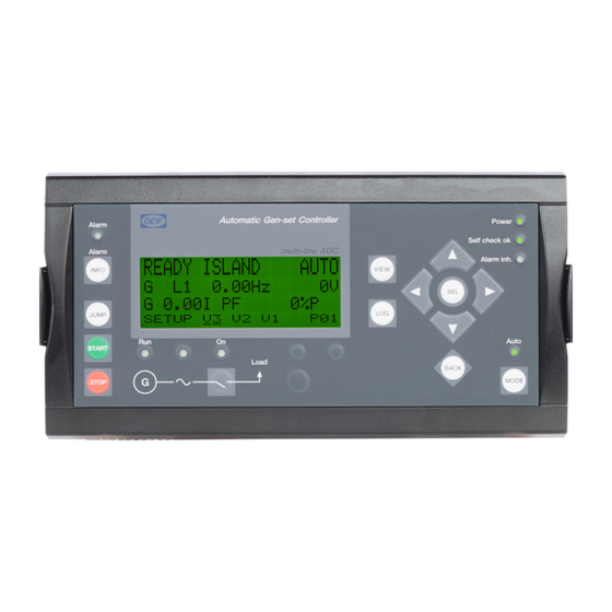
Manual activation of close breaker and open breaker sequence if ‘SEMI-AUTO’ is selected . (MB) ON: Manual activation of close breaker and open breaker sequence if ‘SEMI-AUTO’ is selected . MODE: Changes the menu line (line 4) in the display to mode selection. DEIF A/S Page 51 of 168... - Page 52 LOG: Shifts the display three lower lines to show the event and alarm list. SEL: Selects the underscored entry in the fourth display line. BACK: Jumps one step backwards in the menu. DEIF A/S Page 52 of 168...
- Page 53 LED is green, if the mains is present and OK. LED is red at a measured mains failure. LED is flashing green when the mains returns during the ‘mains OK delay’ time. Auto: LED indicates that auto mode is selected. DEIF A/S Page 53 of 168...
- Page 54 Power: Indicates auxiliary supply ON. Self check OK: Indicates self check OK. Alarm inh.: Indicates alarm inhibit active. Generator running. Generator voltage OK. Generator breaker ON. Mains breaker ON. Mains voltage OK. Auto: ON. Semi-auto: OFF. DEIF A/S Page 54 of 168...
-
Page 55: Menu Structure
It can always be reached by pressing the BACK push-button 3 times. The event and alarm list will appear at power up, if an alarm is present. DEIF A/S Page 55 of 168... - Page 56 View window configuration The individual view windows need to be configured through the PC software in the dialog box illustrated below. Use this button to go to the configuration. Select the view window to be configured. DEIF A/S Page 56 of 168...
- Page 57 If the text ‘no text’ is selected in all 3 lines in a window, it will not be displayed. This is to get a continuous displaying, if a window is not to be used. There is a maximum of 15 configurable view windows in V1. DEIF A/S Page 57 of 168...
- Page 58 Line 2 and line 3 show measurements. * The default window is automatically selected after the generator breaker closure when the gen-set is in normal operation, e.g. fixed power mode after the ramping up. DEIF A/S Page 58 of 168...
- Page 59 System setup • View 3 – window displays operational status and selectable measurements • View 2 – window displays selectable measurements • View 1 – access to up to 15 selectable windows displaying selectable measurements DEIF A/S Page 59 of 168...
- Page 60 Voltage min. (V AC) Analogue 97 PID value #2.1 Current L1 L2 L3 (A) Frequency (Hz) PT100 no. 106 PID value #2.2 Current L1 (A) Frequency/voltage L1 (Hz/ PT100 no. 109 PID value #2.3 DEIF A/S Page 60 of 168...
- Page 61 440V G 439 440V PROTECTION SETUP CONTROL SETUP INPUT/OUTPUT SETUP SYSTEM SETUP SET POINT 1 SETUP SYNCHRONICE SETUP BINARY INPUT SETUP GENERAL SETUP PROT1 PROT2 SYNC REG BIN AIN OUT GEN MAINS COMM PM DEIF A/S Page 61 of 168...
-
Page 62: Mode Overview
In semi-auto mode the operator has to initiate all sequences. This can be done via the push- button functions, Modbus commands or digital inputs. When started in semi-automatic mode, the gen-set will run at nominal values. Test DEIF A/S Page 62 of 168... -
Page 63: Mode Selection
SETUP MENU ‘MODE’ SEMI-AUTO MODE ‘SEL’ SETUP V3 SEMI TST AUT MAN BLK 3. push 4. push f-L1 0.00Hz f-L1 0.00Hz PROTECTION SETUP ‘MODE’ SEMI-AUTO MODE ‘SEL’ PROT CTRL SYST SEMI TST AUT MAN BLK DEIF A/S Page 63 of 168... -
Page 64: Password
Each parameter can be protected at a specific password level. To do so, the PC utility software must be used. Enter the parameter to be configured and select the correct password level. DEIF A/S Page 64 of 168... - Page 65 The factory passwords must be changed, if the operator of the gen-set is not allowed to change the parameters. It is not possible to change the password at a higher level than the password entered. DEIF A/S Page 65 of 168...
-
Page 66: Additional Functions
If an external running relay is installed, then the digital control inputs for running detection or remove starter can be used. Running feedback When the digital running feedback is active, the start relay is deactivated and the starter motor will be disengaged. DEIF A/S Page 66 of 168... - Page 67 The remove starter input must be configured from a number of available digital inputs. In the example above terminal 118 is used. The running feedback is detected by the digital input (see diagram above). Frequency measurement above 32Hz or RPM is measured by magnetic pick-up. DEIF A/S Page 67 of 168...
- Page 68 The factory setting is 400 RPM (6160 Remove starter Run. feedback, menu 4301 Remove starter, menu 6161 Firing speed Running The number of teeth on the flywheel must be adjusted when the tacho input is used (6160 Remove starter DEIF A/S Page 68 of 168...
-
Page 69: Breaker Spring Load Time
There is one input for the generator breaker and one for the mains breaker. The input configuration is done through the PC utility software. The names of the inputs are ‘GB spring loaded’ and ‘MB spring loaded’. In the example below they are configured to terminal 91 and 92. DEIF A/S Page 69 of 168... -
Page 70: Alarm Inhibit
The inhibit LED on the unit and on the display will activate when the voltage is below 30% of the nominal voltage. Digital input 23 The functionality of the alarm inhibit input is indicated in the table below: DEIF A/S Page 70 of 168... - Page 71 Active Active Access lock Binary input Active Active Running feedback Binary input Active Active External engine fail. Active Emergency stop Binary input Active Active Configurable input Binary input Active Option dependent Positive sequence U DEIF A/S Page 71 of 168...
- Page 72 The diagram below illustrates that after activation of the running feedback, a run status delay will expire. When the delay expires, alarms with RUN status will be activated. Run. feedback Alarms active DEIF A/S Page 72 of 168...
- Page 73 The timer is adjusted in the following dialog box: Only the timer needs adjustment to achieve this function. The additional roll down panels are used, if a digital running status output is needed. Refer to page DEIF A/S Page 73 of 168...
- Page 74 To activate the custom inhibit function two things are needed: 1. Configure an input in the input settings in the utility SW. 2. Enable the function as shown in the dialog box below. DEIF A/S Page 74 of 168...
- Page 75 Designer’s Reference Handbook DEIF A/S Page 75 of 168...
- Page 76 Active Option dependent Optional PCBs Custom inhibit input configured Input ON Input OFF Comment Input and custom inhibit enabled Active Digital inputs Option M12 Option M13 Active Digital inputs Active 4-20mA inputs Option M15 DEIF A/S Page 76 of 168...
- Page 77 ON. If the protection is configured to ‘RUN’ or ‘PARALLEL’ the custom inhibit will overrule these functions, if the input is active after the conditions for ‘RUN’ or ‘PARALLEL’ have been removed. DEIF A/S Page 77 of 168...
-
Page 78: Access Lock
The stop push-button is not active in semi-auto mode when the access lock is activated. For safety reasons it is recommended to install an emergency stop switch. DEIF A/S Page 78 of 168... -
Page 79: Short-Time Parallel
The function is typically used, if there are local requirements to maximum allowed paralleling time. The short time paralleling function is only available in the automatic mains failure and load take over gen-set modes. DEIF A/S Page 79 of 168... -
Page 80: Digital Mains Breaker Control
The load will continue on generator supply, if the input is still activated. The mains OK delay is not used at all when the ‘mains OK’ input is configured. DEIF A/S Page 80 of 168... -
Page 81: Time Dependent Start/Stop
MO, TU, WE, TH • MO, TU, WE, TH, FR • MO, TU, WE, TH, FR, SA, SU • SA, SU The digital input ‘auto start/stop’ cannot be used, when this function is enabled. DEIF A/S Page 81 of 168... -
Page 82: Running Output
Derate gen-set The purpose of the derate function is to be able to reduce the maximum output power of the gen-set, if specific conditions require this. An example of such a condition is the ambient DEIF A/S Page 82 of 168... - Page 83 %/C. Be aware that the 4…20mA input can be configured with different minimum and maximum settings. In this case the settings ‘start derate point’ and ‘slope’ use these new settings. DEIF A/S Page 83 of 168...
- Page 84 Derate characteristic It can be selected whether the characteristic of the derating should be proportional or inverse proportional. The drawing above shows the inverse characteristic. The proportional characteristic is illustrated below. LIMIT Start increase DEIF A/S Page 84 of 168...
- Page 85 The gen-set is derated when the control value is lower than the setpoint (in the example above the control value is an mA signal). The derate characteristic is selected in 6260 Pnom derate Setting OFF: Inverse characteristic Setting ON: Proportional characteristic DEIF A/S Page 85 of 168...
-
Page 86: Idle Running
One extra relay output must be available on the unit. Notice that this is option dependent. Turbo chargers not originally prepared for operating in the low speed area can be damaged, if the gen-set is running in ‘idle run’ for too long. DEIF A/S Page 86 of 168... - Page 87 The start and stop sequences are changed in order to let the gen-set stay at the idle level before speeding up. It also decreases the speed to the idle level for a specified delay time before stopping. 1500 START STOP Start Stop DEIF A/S Page 87 of 168...
- Page 88 The alarms that are deactivated by the inhibit function or the alarms with run status are inhibited like usual except for the oil pressure alarms, i.e. VDO 104 if option M2 is selected, and 4…20mA input 100 if option M1 is selected. DEIF A/S Page 88 of 168...
- Page 89 ‘low speed’. Start Start Auto temp control start/stop No starting start the genset start the genset low speed ON Genset running at idle speed idle timer idle timer ON expired genset running at f DEIF A/S Page 89 of 168...
- Page 90 Designer’s Reference Handbook Stop start tem p control auto start/stop genset is running gen-set stop sequence Low speed ON genset running at idle speed idle tim er ON idle tim er expired genset stop sequence DEIF A/S Page 90 of 168...
-
Page 91: Master Clock
The time for the compensation can easily be calculated at a given adjustment of 6403 and 6404 (example): • 6403 = 30 seconds • 6404 = +/- 0.1Hz − 1 /( TOTAL DIFF − 1 /( TOTAL 15030 hours TOTAL DEIF A/S Page 91 of 168... -
Page 92: Battery Test
Otherwise, the test command will be ignored. The stop relay will act depending on the coil type selection in 6210 Stop Stop coil: The stop relay activates during the test. Run coil: The stop relay stays deactivated during the test. DEIF A/S Page 92 of 168... -
Page 93: Fail Class
All activated alarms must be configured with a fail class. The fail classes define the category of the alarms and the subsequent alarm action. Six different fail classes can be used. The tables below illustrate the action of each fail class when the engine is running or stopped. DEIF A/S Page 93 of 168... - Page 94 The fail class can be selected for each alarm function either via the display or the PC software. To change the fail class via the PC software, the alarm function to be configured must be selected. Select the desired fail class in the fail class roll-down panel. DEIF A/S Page 94 of 168...
-
Page 95: Service Timers
Wire failure area Normal range Wire failure area 4-20mA Below 4mA 4-20mA Above 20mA VDO 104 0…40% 60…100% VDO 105 0…40% 60…100% VDO 106 0…40% 60…100% PT100 – 106 0…40% 60…100% PT100 – 109 0…40% 60…100% DEIF A/S Page 95 of 168... - Page 96 The deviation is the alarm value entered in percent, and the setting is the required alarm setting in ohms. Example: Required setpoint of VDO104 is 180 Ω . The adjustment must be: deviation deviation DEIF A/S Page 96 of 168...
-
Page 97: Digital Inputs
Configurable Constant Temperature Configurable Constant control Battery test Configurable Pulse Mains OK Configurable Constant External f control Configurable Constant External P control Configurable Constant External PF Configurable Constant control External U control Configurable Constant DEIF A/S Page 97 of 168... - Page 98 Changes the present running mode to semi-auto. 7. Test Changes the present running mode to test. 8. Auto Changes the present running mode to auto. 9. Manual Changes the present running mode to manual. DEIF A/S Page 98 of 168...
- Page 99 If manual mode is selected, then the governor output will be increased. 20. Manual GOV down If manual mode is selected, then the governor output will be decreased. 21. Manual AVR up If manual mode is selected, then the AVR output will be increased. DEIF A/S Page 99 of 168...
-
Page 100: 4370 Wire Failure Analogue Input
OFF). 32. Battery test Activates the starter motor without starting the gen-set. If the battery is weak, the test will cause the battery voltage to drop more than acceptable, and an alarm will occur. DEIF A/S Page 100 of 168... - Page 101 When the input is activated, then the AGC can close the generator on a black busbar. 45. Enable separate sync. Activating this input will split the breaker close and breaker synchronisation functions into two DEIF A/S Page 101 of 168...
-
Page 102: 4380 Wire Failure Analogue Input
The digital inputs are configured via the PC software. Select the input icon in the horizontal toolbar. The desired input number can now be selected for the individual input function via the roll-down panel. DEIF A/S Page 102 of 168... -
Page 103: Vdo Inputs
If the VDO input is used as a level switch, then be aware that no voltage must be connected to the input. If any voltage is applied to the VDO inputs, then it will be damaged. Refer to the Application Notes for further wiring information. DEIF A/S Page 103 of 168... -
Page 104: 4390 Wire Failure Analogue Input
If the VDO input is used as a level switch, then be aware that no voltage must be connected to the input. If any voltage is applied to the VDO inputs, then it will be damaged. Refer to the Application Notes for further wiring information. DEIF A/S Page 104 of 168... - Page 105 VDO input 104: Lubricating oil pressure – alarm settings in menus 4170/4180. VDO input 105: Cooling water temperature – alarm settings in menus 4190/4200. VDO input 106: Fuel level switch – alarm settings in menus 4210/4220. DEIF A/S Page 105 of 168...
-
Page 106: 4400 Wire Failure Analogue Input
In the PC utility software the configurable inputs are adjusted in this dialog box: Adjust the resistance of the VDO sensor at the specific measuring value. In the example above the adjustment is 10 Ω at 0.0 bar. DEIF A/S Page 106 of 168... -
Page 107: Manual Governor Control
The regulation is activated after 5 seconds or when the increase/decrease button is pushed again within 5 seconds. See the M-logic Manual for details. If option D1 is selected, then the AVR can also be controlled from the AOP similar to the governor control. DEIF A/S Page 107 of 168... -
Page 108: Input Function Selection
Retrieve languages from the device: Activating this button will retrieve the configured languages from the device. Send languages to the device: Activating this button will send the content of the 11 language frames to the device. DEIF A/S Page 108 of 168... - Page 109 In the PC utility software the language is configured in the Translations menu. Activate the menu by pressing the Translations icon (see below): All configurable entries are indicated in the left side column. The list can be scrolled with page DOWN/UP. Example: DEIF A/S Page 109 of 168...
- Page 110 There is a maximum of 20 characters/text. The symbol ##### is included and will in this case use up 5 characters. It is not possible to change the number of characters in the measurement symbol (#####). DEIF A/S Page 110 of 168...
-
Page 111: Texts In Status Line
ISLAND MANUAL If the gen-set is stopped, or if it is running and no other ISLAND SEMI-AUTO action takes place. ISLAND AUTO MANUAL SEMI-AUTO AUTO FIXED MANUAL FIXED SEMI-AUTO FIXED AUTO DEIF A/S Page 111 of 168... - Page 112 This info. is shown during a battery test. Deload This info. is shown when decreasing the load of the gen-set. Starting DG(s) ###s When start gen-set setpoint is exceeded, this info. is shown with the countdown of the timer. DEIF A/S Page 112 of 168...
- Page 113 This info. is shown, if a CAN Option G5 must be available. failure is present in a power management application. Programming language This info. is shown, if the language file is downloaded from the PC utility software. DEIF A/S Page 113 of 168...
-
Page 114: Service Menu
OUT (digital output) Shows the status of the digital outputs. G 400 400 400V Horn Output = UP DOWN MISC (miscellaneous) Shows miscellaneous messages. G 400 400 400V M-logic Enabled Various = UP DOWN DEIF A/S Page 114 of 168... -
Page 115: Event Log
In the right side column additional data is indicated. This is specific data for the most important measurements. The data is logged for each specific event and is used for troubleshooting after each alarm. DEIF A/S Page 115 of 168... -
Page 116: Counters
Counting each start start attempts. attempt. 6086 Running time FP The running hour counter for the fire The running hour counter is pump operation can be reset in this shown in the display. menu. DEIF A/S Page 116 of 168... -
Page 117: M-Logic
PC utility software and not via the display. The M-logic icon is not active as default – ‘Alt + F1’ activates M-logic. The main purpose of M-logic is to give the operator/designer more flexible possibilities of operating the generator control system. DEIF A/S Page 117 of 168... - Page 118 Designer’s Reference Handbook Programming The programming interface in the PC utility software looks like this: Description overview This diagram illustrates the programme sequence without the M-logic function enabled: AGC program sequence DEIF A/S Page 118 of 168...
-
Page 119: Gsm Communication
System single-line diagram External antenna Modem DEIF recommends using a MOXA OnCell G2150I, Wavecom WMOD2 or Westermo GDW-11 terminal, as the application has been tested with these terminals. DEIF A/S Page 119 of 168... -
Page 120: Usw Communication
1 (modem USW) 0 (normal USW) If setting 9020 is set to 1, the PC utility software cannot communicate with the unit when it is connected directly to the PC and a modem is not used. DEIF A/S Page 120 of 168... -
Page 121: Nominal Settings
M-logic is used when a digital input is needed for switching between the two sets of nominal settings. Select the required input among the input events, and select the nominal settings in the outputs. DEIF A/S Page 121 of 168... - Page 122 If the fire pump mode is used with the selection of nominal settings adjusted to ‘OFF’, then the overspeed alarm 2 (4320) must be used to protect the engine from overspeeding. Overspeed 1 (4310) is not active. DEIF A/S Page 122 of 168...
-
Page 123: Pi Controller
The power (and VAr) controller is activated when the gen-set is running parallel to the mains or in load sharing mode. Load sharing mode is option dependent (option G3). DEIF A/S Page 123 of 168... -
Page 124: Principle Drawing
The output from each regulator is added and converted to the output stage which, in this case, is the analogue output. PWM or relay outputs can also be used. Frequency regulator Frequency deviation Analogue output Power deviation Power regulator DEIF A/S Page 124 of 168... -
Page 125: Proportional Regulator
The diagram shows how the output of the P regulator depends on the KP setting. The change of the output at a given KP setting will be doubled, if the regulation deviation doubles. P-regulator 1200 0,5% 1000 DEIF A/S Page 125 of 168... - Page 126 5mA. The table shows that the output of the AGC changes relatively much, if the maximum speed range is low. Max. speed Output change Output change in % of range max. speed range 10mA 5/10*100% 20mA 5/20*100% DEIF A/S Page 126 of 168...
- Page 127 The drawing below shows the dynamic regulation area at given values of KP. The dynamic area gets smaller, if the KP is adjusted to a higher value. Dynamic regulation band KP = 1000 KP = 100 KP = 10 Frequency DEIF A/S Page 127 of 168...
- Page 128 KI = 50 The reset time of the unit can be calculated at all values of KP and KI with the formula: The table shows theoretical reset times in seconds: 1000 0.01 1000 1000 10000 1000 DEIF A/S Page 128 of 168...
-
Page 129: Relay Control
Static range Fix down signal The regulation is active, but the decrease relay will be constantly activated because of the size of the regulation deviation. DEIF A/S Page 129 of 168... - Page 130 If the deviation is big, then the pulses will be long (or a continued signal). If the deviation is small, then the pulses will be short. Relay ON PERIOD PERIOD PERIOD PERIOD PERIOD t [sec] HIGH <DEVIATION> DEIF A/S Page 130 of 168...
- Page 131 The length of the period time will never be shorter than the adjusted ON time. The P regulator causes the relay output to activate. The I regulator has the same effect on the relay output as described on page 126 concerning the reset time t DEIF A/S Page 131 of 168...
-
Page 132: Synchronisation
Synchronisation principle - dynamic synchronisation Load Speed: Speed: 1503 RPM 1500 RPM 50.1 Hertz 50.00 Hertz Synchronising generator Generator on load Angle Synchronised [deg] 180° 90° ∆t [s] 0° 2.5 s 5.0 s 7.5 s DEIF A/S Page 132 of 168... - Page 133 Illustration 2 below shows that at a given negative slip frequency, the incoming gen-set will receive power from the original gen-set. This phenomenon is called reverse power . DEIF A/S Page 133 of 168...
- Page 134 (+/- value). the busbar/mains and the generator. 2024 t Generator breaker closing Adjust the response time of the generator breaker. time. 2025 t Mains breaker closing Adjust the response time of the mains breaker. time. DEIF A/S Page 134 of 168...
-
Page 135: Static Synchronisation
The static principle is illustrated below. Synchronisation principle - static synchronisation Load Speed: Speed: 1500.3 RPM 1500 RPM 50.01 Hertz 50.00 Hertz Synchronising generator Generator on load α α α Angle Synchronised [deg] 20° 10° t [s] 0° DEIF A/S Page 135 of 168... - Page 136 If the maximum df setting is adjusted to a high value, then the observations in the section about ‘dynamic synchronisation’ must be observed. DEIF A/S Page 136 of 168...
-
Page 137: Gb Closing Before Excitation
The function can be used in the single AGC but also the AGC with option G5. The only exception is that when option G3 is selected, then the ‘close before excitation’ function is not available. The principle is described in the flowcharts below. DEIF A/S Page 137 of 168... - Page 138 Designer’s Reference Handbook Flowchart abbreviations Delay 1 Menu 2112 Delay 2 Menu 2122 Delay 3 Menu 2131 Menu 2111 Menu 2123 DEIF A/S Page 138 of 168...
- Page 139 Delay 1 expired on all DG(s) Activate Delay 2 Start Delay 2 regulators expired expired excitation Activate Delay 3 regulators expired "Close before Delay 3 excitation" expired failure "Close before Sync GB excitation" failure DEIF A/S Page 139 of 168...
- Page 140 Designer’s Reference Handbook Flowchart 2, TB handling (option G5) START TB Open Any GB closed > P AVAIL "GB + TB" MB OFF Close TB Sync TB DEIF A/S Page 140 of 168...
- Page 141 In one of the applications a tie breaker is present, and it must be adjusted in the menu 2121 whether only the generator breaker must be closed or both the generator breaker and also the tie breaker. DEIF A/S Page 141 of 168...
-
Page 142: Separate Synchronising Relay
Blackout closing: The breaker ON relay and the sync. The breaker ON relay activates when relay activate at the same time when the voltage and frequency are OK. the voltage and frequency are OK. DEIF A/S Page 142 of 168... - Page 143 Care must be taken that the GB ON relay cannot close the breaker, before the sync. signal is issued by the sync. relay. The selected relay for this function must have the ‘limit’ function. This is adjusted in the I/O setup. DEIF A/S Page 143 of 168...
-
Page 144: Procedure For Parameter Setup
The descriptions are structured according to their parameter titles and the main parameter group to which they belong. Find the individual parameter title in the overview list on page 146. In the overview list you will find the page location of the parameter description you are looking for. DEIF A/S Page 144 of 168... -
Page 145: Parameter Descriptions
Enter the ‘setpoint’ menu via LIM in the fourth display line Step 6: Enter password to change the setpoint Step 7: Use the push-buttons to increase/decrease the setpoint setting Step 8: Use the ’underscore’ to save the new setpoint setting DEIF A/S Page 145 of 168... -
Page 146: 10. Parameter List
By using the PC utility software some extra functionalities are available. For all the protections it is possible to make an automatic acknowledgement of the alarm. Usually it is important when the mains protections are used, as the sequences are blocked until the alarm is acknowledged. DEIF A/S Page 146 of 168... - Page 147 Designer’s Reference Handbook DEIF A/S Page 147 of 168...
-
Page 148: Overview List
4240 Water temperature p. 157 6590 Mains failure voltage p. 166 4260 PT100 input 109.1 p. 157 6600 Mains failure frequency p. 167 4300 Running detection p. 157 6610 Mains breaker control p. 167 DEIF A/S Page 148 of 168... - Page 149 Jump menus 9000 Software version p. 167 Power management setup p. 167 9020 Service port p. 167 911X User password p. 167 9120 Service menu p. 168 9130 Single phase/split phase/three phase p. 168 DEIF A/S Page 149 of 168...
-
Page 150: Protection
Static sync. Dynamic Dynamic sync. sync. If dynamic synchronisation is chosen, the next menu will be 2020 Dynamic synchronisation . If static synchronisation is chosen, the next menu will be 2030 Static synchronisation . DEIF A/S Page 150 of 168... -
Page 151: 2020 Dynamic Synchronisation
The general failure alarms cannot be disabled. 2080 MB general failure - Synchronisation time Adjustable time delay channel 2081 - Breaker ON/OFF feedback fail. 1 second fixed time delay - Phase sequence error 1 second fixed time delay DEIF A/S Page 151 of 168... -
Page 152: 2090 Breaker Failure Alarms
Relay output A R0 (none) Option R0 (none) dependent 2133 Excit. failure Relay output B R0 (none) R0 (none) 2134 Excit. failure Enable 2135 Excit. failure Fail class Alarm (1) Trip MB (6) Warning (2) DEIF A/S Page 152 of 168... -
Page 153: 2510 Frequency Controller
Governor reg. failure Output B R0 (none) R0 (none) The alarm is activated, if the difference between the measured value and the setpoint is outside the setpoint for a longer time period than specified by the timer setpoint. DEIF A/S Page 153 of 168... -
Page 154: Input/Output
Dig. input no. 111 Relay output B R0 (none) dependent R0 (none) 3274 Dig. input no. 111 Enable 3275 Dig. input no. 111 Fail class Alarm (1) Trip MB (6) Warning (2) 3276 Dig. input no. 111 Type DEIF A/S Page 154 of 168... -
Page 155: 3280 Dig. Input No. 112 (Option M2)
R0 (none) dependent 3323 Engine failure Relay output B R0 (none) R0 (none) 3324 Engine failure Enable 3325 Engine failure Fail class Alarm (1) Trip MB (6) - Shutdown (5) 3326 Engine failure Type DEIF A/S Page 155 of 168... -
Page 156: 3330 Ext. Emergency Stop (Binary Input 117)
R0 (none) dependent - 4104 4…20mA input 98.2 Relay output B R0 (none) R0 (none) 4105 4…20mA input 98.2 Enable 4106 4…20mA input 98.2 Fail class Alarm (1) Trip MB (6) - Warning (2) DEIF A/S Page 156 of 168... -
Page 157: 4110 Oil Pressure
Option R0 (none) dependent 4154 4…20mA input 104.1 Relay output B R0 (none) R0 (none) 4155 4…20mA input 104.1 Enable 4156 4…20mA input 104.1 Fail class Alarm (1) Trip MB (6) - Warning (2) DEIF A/S Page 157 of 168... -
Page 158: 4170 Vdo 104.1 (Option M2)
Relay output A R0 (none) Option R0 (none) dependent 4204 VDO 105.2 Relay output B R0 (none) R0 (none) 4205 VDO 105.2 Enable 4206 VDO 105.2 Fail class Alarm (1) Trip MB (6) - Trip/stop (4) DEIF A/S Page 158 of 168... -
Page 159: 4210 Vdo 106.1 (Option M2)
Max. setting Factory setting 4301 Running detection Setpoint 1 RPM 4000 RPM 1000 RPM 4302 Running detection Type Frequency detection Running detection Type Tacho Running detection Type Binary input Running detection Type Engine I/F communication DEIF A/S Page 159 of 168... - Page 160 R0 (none) dependent 4402 W. fail. ana. 104 Output B R0 (none) R0 (none) 4403 W. fail. ana. 104 Enable 4404 W. fail. ana. 104 Fail class Alarm (1) Trip MB (6) Warning (2) DEIF A/S Page 160 of 168...
-
Page 161: 4430 Wire Failure Vdo Input 106 (M2)
R0 (none) dependent 4434 W. fail. VDO 106 Output B R0 (none) R0 (none) 4435 W. fail. VDO 106 Enable 4436 W. fail. VDO 106 Fail class Alarm (1) Trip MB (6) Warning (2) DEIF A/S Page 161 of 168... -
Page 162: Output Setup
5491 Transistor 20 Continues 5492 Transistor 21 Continues kVAr kVArh If the transistor outputs are set to ‘Continues’, external relays are needed due to the limited current output of the transistors. Max 10mA. DEIF A/S Page 162 of 168... -
Page 163: System
If no voltage transformer is present, the primary and secondary side values are set to generator nominal value. 6050 Engine type Setting First setting Second Factory setting setting 6051 Engine type Engine type Diesel None Diesel engine engine It is only possible to select diesel engine. DEIF A/S Page 163 of 168... -
Page 164: 6060 Gen-Set Modes
Relay output A R0 (none) Option R0 (none) 6093 Service timer Relay output B R0 (none) dependent R0 (none) 6094 Service timer Enable 6095 Service timer Fail class Alarm (1) Trip MB (6) Warning (2) DEIF A/S Page 164 of 168... -
Page 165: 6110 Battery Low Voltage Alarm
Run status Enable 6160 Remove starter Setting Min. setting Max. setting Factory setting 6161 Remove starter Setpoint 1 RPM 2000 RPM 400 RPM 6162 Remove starter Number of teeth 0 teeth 500 teeth 0 teeth DEIF A/S Page 165 of 168... -
Page 166: 6170 Starter
R0 (none) 6250 GB control Setting Min. setting Max. setting Factory setting 6251 GB control Timer t 0.0 s 30.0 s 2.0 s 6252 GB control GB load time 0.0 s 30.0 s 0.0 s DEIF A/S Page 166 of 168... -
Page 167: 6260 Pnom Derate
750 kW 6502 Mains power Night -20000 kW 20000 kW 1000 kW 6503 Mains power Transducer max 0 kW 20000 kW 1500 kW 6504 Mains power Transducer min -20000 kW 0 kW -1500 kW DEIF A/S Page 167 of 168... -
Page 168: 6510 Daytime Period
Mains failure U Low voltage 100% 6594 Mains failure U High voltage 100% 120% 110% 6595 Mains failure U Mains fail. control Start eng. + Start eng. Start eng. + open MB open MB DEIF A/S Page 168 of 168... -
Page 169: Communication Setup
9000 Software version Information about the actual software downloaded to the unit. Please check this before contacting DEIF regarding service and support matters. 9020 Service port The RS232 service port can be set up to use the ASCII communication. The ASCII communication is used when the utility software is connected through a modem. - Page 170 9130 Single phase/split phase/three phase Setting Description 9131 Mode Mode 0 = Three phase system 1 = Split phase system 2 = Single phase system DEIF A/S reserves the right to change any of the above. DEIF A/S Page 170 of 168...
Need help?
Do you have a question about the Multi-line 2 and is the answer not in the manual?
Questions and answers