Deif AGC-4 Operator's Manual
Automatic genset controller
Hide thumbs
Also See for AGC-4:
- Quick start manual (26 pages) ,
- Operator's manual (24 pages) ,
- General manuallines for commissioning (25 pages)
Advertisement
Table of Contents
- 1 Warnings, Legal Information and Safety
- 2 Factory Settings
- 3 Push-Button Functions
- 4 LED Functions
- 5 General
- 6 LCD Display
- 7 View Menu
- 8 View Window 1
- 9 View Window 3
- 10 Status Line Text
- 11 Texts Only Related to Power Management (Option G5)
- 12 View Menu Example
- 13 Mode Menu
- 14 Alarm Handling
- Download this manual
Advertisement
Table of Contents

Related Manuals for Deif AGC-4


Summary of Contents for Deif AGC-4
- Page 1 ● Log list DEIF A/S · Frisenborgvej 33 · DK-7800 Skive · Tel.: +45 9614 9614 · Fax: +45 9614 9615 · info@deif.com · www.deif.com isenborgvej 33 · DK-7800 Skive · Tel.: +45 9614 9614 · Fax: +45 9614 9615 · info@deif.com · www.deif.com Document no.: 4189340690C...
- Page 2 2. Display push-buttons and LEDs 2.1. Push-button functions..........................5 2.2. LED functions............................6 3. Display and menu structure 3.1. General..............................7 3.2. Display layouts for AGC-4........................7 3.3. LCD display............................9 3.4. Menu structure............................9 3.4.1. Entry window..........................9 3.4.2. View menu........................... 10 3.4.3.
-
Page 3: Warnings, Legal Information And Safety
1.1.2 Legal information and disclaimer DEIF takes no responsibility for installation or operation of the generator set. If there is any doubt about how to install or operate the engine/generator controlled by the Multi-line 2 unit, the company responsible for the installation or the operation of the set must be contacted. -
Page 4: Factory Settings
AGC-4 operator's manual 4189340690 UK General information 1.1.5 Factory settings The Multi-line 2 unit is delivered from factory with certain factory settings. These are based on average values and are not necessarily the correct settings for matching the engine/generator set in question. Precautions must be taken to check the settings before running the engine/generator set. -
Page 5: Push-Button Functions
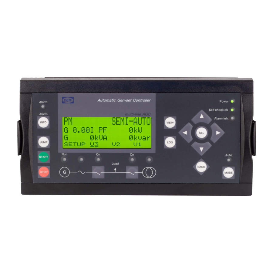
AGC-4 operator's manual 4189340690 UK Display push-buttons and LEDs 2. Display push-buttons and LEDs 2.1 Push-button functions The display unit holds a number of push-button functions which are described below: Automatic Gen-set Controller Power Alarm Self check ok Alarm multi-line AGC Alarm Inh. -
Page 6: Led Functions
AGC-4 operator's manual 4189340690 UK Display push-buttons and LEDs 2.2 LED functions The display unit holds 10 LED functions. The colour is green or red or a combination in different situations. The display LEDs are indicating as follows: Automatic Gen-set Controller... -
Page 7: General
AGC-4 operator's manual 4189340690 UK Display and menu structure 3. Display and menu structure 3.1 General This chapter deals with the display unit including the push-button and LED functions. In addition, the unit menu structure will be presented. 3.2 Display layouts for AGC-4 The display dimensions are H x W = 115 x 220 mm (4.528”... - Page 8 AGC-4 operator's manual 4189340690 UK Display and menu structure Generator breaker and mains breaker control (option Y3) Automatic Gen-set Controller Power Alarm Self check ok Alarm multi-line AGC Alarm Inh. INFO VIEW JUMP Auto START Load BACK STOP MODE Tie breaker and mains breaker control (option Y4)
-
Page 9: Lcd Display
AGC-4 operator's manual 4189340690 UK Display and menu structure Bus tie breaker control (option Y5) Automatic Gen-set Controller Power Alarm Self check ok multi-line AGC Alarm BUS TIE Alarm Inh. INFO VIEW JUMP Auto BACK MODE 3.3 LCD display The display is a backlit LCD text display containing four lines with 20 characters in each line. There is no con- trol of the display light intensity (no dimmer). -
Page 10: View Menu
AGC-4 operator's manual 4189340690 UK Display and menu structure Automatic Gen-set Controller multi-line AGC 400V f-L1 50.00HZ PROTECTION SETUP PROT CTRL POWER SYST 3.4.2 View menu The view menus (V1, V2 and V3) are the daily use menus for the operator. -
Page 11: View Window 1
AGC-4 operator's manual 4189340690 UK Display and menu structure 3.4.4 View window 1 Display of measured values according to the selections made during configuration. For detailed information about configuration, please see the Designer’s Reference Handbook. V1 contains up to 15 different windows which can be selected using the push-buttons located on the right hand side of the display. -
Page 12: View Window 3
AGC-4 operator's manual 4189340690 UK Display and menu structure Windows View 1 View 2 Changes automatically between View 3 Changes automatically between the five first views: View 4 the five first views: View 5 1. View 1 (Start prepare) 1. View 1 (Start prepare) 2. - Page 13 AGC-4 operator's manual 4189340690 UK Display and menu structure Windows View 1 View 2 Changes automatically between View 3 Changes automatically between the five first views: View 4 the five first views: View 5 1. View 1 (Start prepare) 1. View 1 (Start prepare) 2.
-
Page 14: Status Line Text
AGC-4 operator's manual 4189340690 UK Display and menu structure 3.5 Status line text 3.5.1 Standard texts Status text Condition Comment BLOCK Block mode is activated SIMPLE TEST Test mode is activated LOAD TEST FULL TEST SIMPLE TEST ###.#min Test mode activated and test timer counting down LOAD TEST ###.#min... - Page 15 AGC-4 operator's manual 4189340690 UK Display and menu structure Status text Condition Comment GB ON BLOCKED Generator running, GB open and an active "Trip GB" alarm SHUTDOWN OVERRIDE The configurable input is active ACCESS LOCK The configurable input is activated, and the operator...
- Page 16 AGC-4 operator's manual 4189340690 UK Display and menu structure Status text Condition Comment COOLING DOWN Cooling down period is activated and infinite Cooling down tim- er is set to 0.0 s GENSET STOPPING This info is shown when cooling down has finished EXT.
-
Page 17: Texts Only Related To Power Management (Option G5)
AGC-4 operator's manual 4189340690 UK Display and menu structure 3.5.2 Texts only related to power management (option G5) Status text Condition Comment DG unit BLACKOUT ENABLE This info is shown if a CAN failure is present in a pow- er management application. -
Page 18: View Menu Example
AGC-4 operator's manual 4189340690 UK Display and menu structure Status text Condition Comment BROADCAST COMPLE- Successful broadcast of an application. RECEIVE COMPLETED Application received successfully. BROADCAST ABORTED Broadcast terminated. RECEIVE ERROR Application is not received correctly. 3.5.3 View menu example The following is an example of a configured view menu system. -
Page 19: Mode Menu
AGC-4 operator's manual 4189340690 UK Display and menu structure 3.6 Mode menu If the MODE push-button is pushed, a selection of possible running modes appears in the fourth display line. Using the push-buttons moves the cursor, and the appropriate mode can be selected by pressing... -
Page 20: Alarm Handling
AGC-4 operator's manual 4189340690 UK Alarm handling and log list 4. Alarm handling and log list 4.1 Alarm handling When an alarm occurs, the unit will automatically go to the alarm list for display of the alarm. If reading of the alarms is not desired, use the BACK push-button to exit the alarm list. - Page 21 AGC-4 operator's manual 4189340690 UK Alarm handling and log list 2. Select the list which is needed by using the push-buttons and press the SEL push-button. 3. To scroll up and down in the list, use the push-buttons. It is also possible to go to the first (oldest) logging or the last (most recent) logging by placing the cursor...
Need help?
Do you have a question about the AGC-4 and is the answer not in the manual?
Questions and answers
Alarm not listed in manual. Please clarify "30 minute data storage" and "Storage HW Failure"
"30 minute data storage" refers to a function where the DEIF AGC-4 stores operational data for the last 30 minutes. This is useful for diagnostics and analysis.
"Storage HW Failure" is an alarm indicating a hardware failure in the storage component responsible for saving this data. This means the controller may not be able to save or retrieve historical data properly.
This answer is automatically generated
EIC Protect lamp warning problem