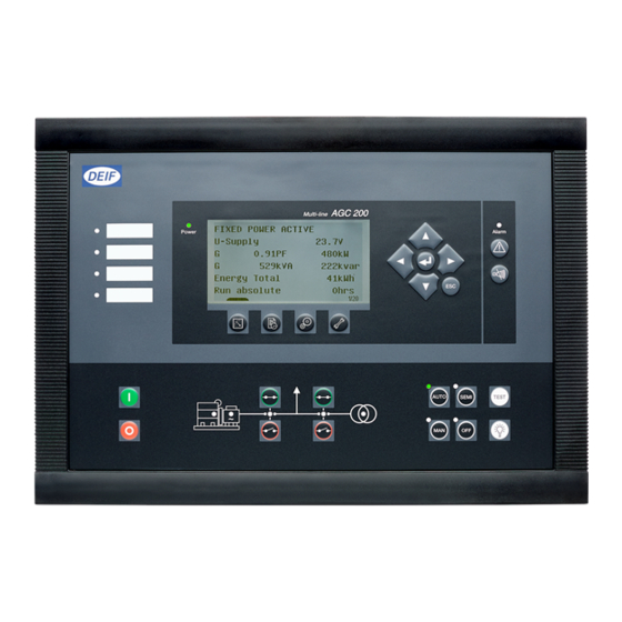
Deif AGC 200 Installation Instructions Manual
Advanced genset controller
Hide thumbs
Also See for AGC 200:
- Operator's manual (25 pages) ,
- General manuallines for commissioning (25 pages) ,
- Quick start manual (21 pages)
Table of Contents
Advertisement
Quick Links
Advertisement
Table of Contents

Related Manuals for Deif AGC 200


Summary of Contents for Deif AGC 200
- Page 1 ● Wiring DEIF A/S · Frisenborgvej 33 · DK-7800 Skive · Tel.: +45 9614 9614 · Fax: +45 9614 9615 · info@deif.com · www.deif.com isenborgvej 33 · DK-7800 Skive · Tel.: +45 9614 9614 · Fax: +45 9614 9615 · info@deif.com · www.deif.com Document no.: 4189340610I...
-
Page 2: Table Of Contents
2.3.9. Multiple gensets, load sharing (power management)..............15 2.3.10. Multiple gensets, power management (AGC 24x and 222 only) ..........16 3. Mounting 3.1. AGC 200 mounting and dimensions.....................17 3.1.1. Mounting of the unit ........................17 3.1.2. Unit dimensions .......................... 17 3.1.3. - Page 3 AGC 200 installation instructions 4189340610 UK 5.1.2. Neutral line (N) ..........................34 5.1.3. Current transformer ground ......................34 5.1.4. Voltage measurement fuses ....................... 34 5.1.5. Breaker wiring ..........................34 5.1.6. 3-phase AGC 213/233/243 ......................35 5.1.7. Single phase AGC 213/233/243 ....................37 5.1.8. 2-phase L1L2 AGC 213/233/243 ....................39 5.1.9.
-
Page 4: General Information
1.1.2 Legal information and disclaimer DEIF takes no responsibility for installation or operation of the generator set. If there is any doubt about how to install or operate the engine/generator controlled by the Multi-line 2 unit, the company responsible for the installation or the operation of the set must be contacted. -
Page 5: Factory Settings
AGC 200 installation instructions General information 4189340610 UK 1.1.5 Factory settings The Multi-line 2 unit is delivered from factory with certain factory settings. These are based on average values and are not necessarily the correct settings for matching the engine/generator set in question. Precautions must be taken to check the settings before running the engine/generator set. -
Page 6: General Product Information
2.1 AGC 200 product information 2.1.1 Introduction The AGC 200 is a part of the DEIF Multi-line 2 product family. AGC 200 is a complete range of multi-function generator protection and control products, integrating all the functions you need into one compact and attrac- tive solution. -
Page 7: Available Can Ports
AGC 200 installation instructions General product information 4189340610 UK 2.1.5 Available CAN ports The table below shows available CAN ports and how each can be configured: CAN A CAN B CAN C AGC 212, 213 Not available Not available External I/O... -
Page 8: Engine Control (Agc 212/213/222/232/242/243)
2.3.1 Standard and optional applications In the following sections, the standard and optional applications of the AGC 200 will be presented. In addition, the correct application configuration for the different applications is listed. It is only possible to use the unit for one of the purposes, for example AMF (Automatic Mains Failure). -
Page 9: Automatic Mains Failure, Amf
AGC 200 installation instructions General product information 4189340610 UK 2.3.2 Automatic Mains Failure, AMF Load AGC 200 Setting 6070 Genset mode DEIF A/S Page 9 of 67... -
Page 10: Island Operation
AGC 200 installation instructions General product information 4189340610 UK 2.3.3 Island operation Load AGC 200 Setting 6070 Genset mode Island operation DEIF A/S Page 10 of 67... -
Page 11: Fixed Power/Base Load
AGC 200 installation instructions General product information 4189340610 UK 2.3.4 Fixed power/base load Load AGC 200 Setting 6070 Genset mode Fixed power DEIF A/S Page 11 of 67... -
Page 12: Peak Shaving
AGC 200 installation instructions General product information 4189340610 UK 2.3.5 Peak shaving Mains breaker AGC 200 (MB) Load Generator breaker (GB) Diesel generator set Setting 6070 Genset mode Peak shaving DEIF A/S Page 12 of 67... -
Page 13: Load Takeover
AGC 200 installation instructions General product information 4189340610 UK 2.3.6 Load takeover Mains breaker AGC 200 (MB) Load Generator breaker (GB) Diesel generator set Setting 6070 Genset mode Load takeover DEIF A/S Page 13 of 67... -
Page 14: Mains Power Export (Fixed Power To Mains)
AGC 200 installation instructions General product information 4189340610 UK 2.3.7 Mains power export (fixed power to mains) Mains breaker AGC 200 (MB) Load Generator breaker (GB) Diesel generator set Setting 6070 Genset mode Mains power export 2.3.8 Multiple gensets, CANshare... -
Page 15: Multiple Gensets, Load Sharing (Power Management)
AGC 200 installation instructions General product information 4189340610 UK 2.3.9 Multiple gensets, load sharing (power management) Load AGC 200 AGC 200 Setting 6070 Genset mode Power management If no mains is configured in a power management system, the genset will automatically be in "island mode", so channel 6071 must be "power management". -
Page 16: Multiple Gensets, Power Management (Agc 24X And 222 Only)
AGC 200 installation instructions General product information 4189340610 UK 2.3.10 Multiple gensets, power management (AGC 24x and 222 only) AGC 245/246 AGC 245 controller (mains) MB17 AGC 246 controller (mains and tie breaker) Load AGC 244 bus tie breaker controller... -
Page 17: Mounting
AGC 200 installation instructions Mounting 4189340610 UK 3. Mounting 3.1 AGC 200 mounting and dimensions 3.1.1 Mounting of the unit The unit is designed for mounting in the panel front. 3.1.2 Unit dimensions 312 (12.28) 87 (3.43) 8 (0.31) 297 (11.69) Dimensions are given in mm (inches). -
Page 18: Panel Cutout
AGC 200 installation instructions Mounting 4189340610 UK 3.1.3 Panel cutout 204 (8.03) Dimensions are given in mm (inches). 3.1.4 Mounting instructions Fasten the unit with the screw clamps supplied with the unit. These are to be tightened 0.15-0.20 Nm - see diagram in the chapter Unit dimensions. -
Page 19: Tightening Torques
AGC 200 installation instructions Mounting 4189340610 UK Mount the gasket as shown in the illustration below. AGC 200 housing Gasket Panel door Furthermore, it is necessary to use all 12 screw clamps to ensure IP65 tightness. 3.1.6 Tightening torques Unit panel door mounting: 0.15-0.20 Nm, 1.4-1.8 lb-in... -
Page 20: Hardware
AGC 200 installation instructions Hardware 4189340610 UK 4. Hardware 4.1 AGC 200 hardware 4.1.1 Unit rear side overview 45 44 43 42 41 40 39 38 37 36 MULTI INPUT 15 14 13 12 11 10 9 GB OFF CAN C... -
Page 21: Terminal Strip Overview, Agc 21X, 222, 232, 233, 242, 243
AGC 200 installation instructions Hardware 4189340610 UK 4.1.2 Terminal strip overview, AGC 21x, 222, 232, 233, 242, 243 AGC 21x: CAN C only. AGC 222: CAN B and C. AGC 23x/24x: CAN A, B and C. AGC 21x, 22x: Terminals 28 to 35 and 22 to 24 are not available. - Page 22 AGC 200 installation instructions Hardware 4189340610 UK Terminal 93 (D+) has two purposes. See chapter 6 for details. The placement of terminals (top, bottom, left, right) is seen from the rear side of the unit. Terminals 77 to 81 are not available in AGC 21x and 22x.
- Page 23 AGC 200 installation instructions Hardware 4189340610 UK Plug #2, communication Term. Function Technical data Description Data+ (A) RS-485 Modbus RTU, max. 115 kBps Data+ (B) CAN A H CAN port A (not 21x, 22x CANshare, power management, AOP-2 and external I/O...
- Page 24 AGC 200 installation instructions Hardware 4189340610 UK Plug #5, relay group 2 Not available for AGC 21x/22x. Term. Function Technical data Description Relay 28 8 A, 30 V DC/250 V AC Configurable Relay 30 8 A, 30 V DC/250 V AC...
- Page 25 AGC 200 installation instructions Hardware 4189340610 UK Plug #8, AC current inputs CT on terminals 59-60: Not available for AGC 21x/22x. Term. Function Technical data Description L1 s1 1 or 5 A AC Current phase L1 L1 s2 L2 s1...
- Page 26 AGC 200 installation instructions Hardware 4189340610 UK Plug #10, mains AC voltage inputs Term. Function Technical data Description 100 to 690 V AC Mains line 1 Not used 100 to 690 V AC Mains line 2 Not used 100 to 690 V AC...
- Page 27 AGC 200 installation instructions Hardware 4189340610 UK Terminals 87 to 90 are configurable in AGC 222. Socket connections Term. Function Technical data Description Memory SD memory Additional memory space for lifetime logging of data PC conn USB B Connection for PC programming...
-
Page 28: Terminal Strip Overview, Agc 244/245/246
AGC 200 installation instructions Hardware 4189340610 UK 4.1.3 Terminal strip overview, AGC 244/245/246 Relays 41 and 43 are not available in AGC 245. Relays 36 and 39 are configurable in AGC 244. DEIF A/S Page 28 of 67... - Page 29 AGC 200 installation instructions Hardware 4189340610 UK Inputs 87 and 88 are configurable in AGC 244. The placement of terminals (top, bottom, left, right) is seen from the rear side of the unit. Input/output lists In the I/O lists below, the following terms will be used in connection with the relay outputs:...
- Page 30 AGC 200 installation instructions Hardware 4189340610 UK Plug #2, communication Term. Function Technical data Description Data+ (A) RS-485 Modbus RTU, max. 115 kBps Data+ (B) CAN A H CAN port A Power management, AOP-2 and external I/O modules CAN A L...
- Page 31 AGC 200 installation instructions Hardware 4189340610 UK Plug #5, relay group 2 Term. Function Technical data Description Relay 28 8 A, 30 V DC/250 V AC Configurable Relay 30 8 A, 30 V DC/250 V AC Configurable Relay 32 8 A, 30 V DC/250 V AC...
- Page 32 AGC 200 installation instructions Hardware 4189340610 UK Plug #8, AC current inputs Term. Function Technical data Description L1 s1 1 or 5 A AC Current phase L1 L1 s2 L2 s1 1 or 5 A AC Current phase L2 L2 s2...
- Page 33 AGC 200 installation instructions Hardware 4189340610 UK Plug #11, digital inputs and breaker positions Term. Function Technical data Description Di 77 Optocoupler Configurable Di 78 Optocoupler Configurable Di 79 Optocoupler Configurable Di 80 Optocoupler Configurable Di 81 Optocoupler Configurable Di 82...
-
Page 34: Wirings
5. Wirings 5.1 AC connections 5.1.1 AC connections The AGC 200 can be wired up in three-phase, single phase or split phase configuration. Contact the switchboard manufacturer for accurate information about required wiring for the specific application. 5.1.2 Neutral line (N) When three-phase distribution systems are used, the neutral line (N) is only necessary if it is a three-phase + neutral system. -
Page 35: 3-Phase Agc 213/233/243
AGC 200 installation instructions Wirings 4189340610 UK 5.1.6 3-phase AGC 213/233/243 AMF, fixed power, peak shaving, load takeover, mains power export. MAINS AGC 200 MAINS VOLTAGE MB OFF FEEDBACK MB ON MB OFF CONTROL MB ON GB OFF LOAD FEEDBACK... - Page 36 AGC 200 installation instructions Wirings 4189340610 UK Wiring indicated with dashed line is optional. For peak shaving, load takeover and mains power export, the configurable current input can be used to measure phase L1 current. The application shown is for pulse breakers.
-
Page 37: Single Phase Agc 213/233/243
AGC 200 installation instructions Wirings 4189340610 UK 5.1.7 Single phase AGC 213/233/243 MAINS AGC 200 MAINS VOLTAGE MB OFF FEEDBACK MB ON MB OFF CONTROL MB ON GB OFF LOAD FEEDBACK GB ON GB OFF CONTROL GB ON GENERATOR VOLTAGE... - Page 38 AGC 200 installation instructions Wirings 4189340610 UK Wiring indicated with dashed line is optional. The application shown is for pulse breakers. Terminals 59 and 60 are not available on AGC 21x and AGC 22x. Be aware that the inputs for feedbacks shown above also need a common wire on terminal 91.
-
Page 39: 2-Phase L1L2 Agc 213/233/243
AGC 200 installation instructions Wirings 4189340610 UK 5.1.8 2-phase L1L2 AGC 213/233/243 MAINS AGC 200 MAINS VOLTAGE MB OFF FEEDBACK MB ON MB OFF CONTROL MB ON GB OFF LOAD FEEDBACK GB ON GB OFF CONTROL GB ON GENERATOR VOLTAGE... - Page 40 AGC 200 installation instructions Wirings 4189340610 UK Wiring indicated with dashed line is optional. The application shown is for pulse breakers. Terminals 59 and 60 are not available on AGC 21x and AGC 22x. Be aware that the inputs for feedbacks shown above also need a common wire on terminal 91.
-
Page 41: 2-Phase L1L3 (Split Phase)
AGC 200 installation instructions Wirings 4189340610 UK 5.1.9 2-phase L1L3 (split phase) MAINS AGC 200 MAINS VOLTAGE MB OFF FEEDBACK MB ON MB OFF CONTROL MB ON GB OFF LOAD FEEDBACK GB ON GB OFF CONTROL GB ON GENERATOR VOLTAGE... - Page 42 AGC 200 installation instructions Wirings 4189340610 UK Wiring indicated with dashed line is optional. The phase angle between L1 and L3 voltages is 180°. The application shown is for pulse breakers. Terminals 59 and 60 are not available on AGC 21x and AGC 22x.
-
Page 43: Island Mode And Power Management (Agc 212/222/232/242/243)
AGC 200 installation instructions Wirings 4189340610 UK 5.1.10 Island mode and power management (AGC 212/222/232/242/243) BUSBAR AGC 200 MAINS VOLTAGE GB OFF FEEDBACK GB ON GB OFF CONTROL GB ON GENERATOR VOLTAGE CONFIGURABLE CURRENT GENERATOR CURRENT GENERATOR DEIF A/S Page 43 of 67... - Page 44 AGC 200 installation instructions Wirings 4189340610 UK Wiring indicated with dashed line is optional. 1-phase and 2-phase systems are also supported. The application shown is for pulse breakers. Terminals 59 and 60 are not available on AGC 21x and AGC 22x.
-
Page 45: Power Management Mains Breaker (Agc 245)
AGC 200 installation instructions Wirings 4189340610 UK 5.1.11 Power management mains breaker (AGC 245) MAINS AGC 200 MAINS VOLTAGE CONFIGURABLE CURRENT MAINS CURRENT MB OFF FEEDBACK MB ON MB OFF CONTROL MB ON LOAD BUSBAR VOLTAGE BUSBAR Wiring indicated with dashed line is optional. - Page 46 AGC 200 installation instructions Wirings 4189340610 UK 1-phase and 2-phase systems are also supported. The application shown is for pulse breakers. Be aware that the inputs for feedbacks shown above also need a common wire on terminal 91. (Terminal 91 is common for 77 to 90).
-
Page 47: Power Management Mains And Tie Breaker (Agc 246)
AGC 200 installation instructions Wirings 4189340610 UK 5.1.12 Power management mains and tie breaker (AGC 246) MAINS AGC 200 MAINS VOLTAGE CONFIGURABLE CURRENT MAINS CURRENT MB OFF FEEDBACK MB ON MB OFF CONTROL MB ON TB OFF LOAD FEEDBACK TB ON... - Page 48 AGC 200 installation instructions Wirings 4189340610 UK 1-phase and 2-phase systems are also supported. The application shown is for pulse breakers. Be aware that the inputs for feedbacks shown above also need a common wire on terminal 91. (Terminal 91 is common for 77 to 90).
-
Page 49: Power Management Agc 244 Btb
AGC 200 installation instructions Wirings 4189340610 UK 5.1.13 Power management AGC 244 BTB BUSBAR B AGC 200 BUSBAR B VOLTAGE BTB OFF FEEDBACK BTB ON BTB OFF CONTROL BTB ON BUSBAR A VOLTAGE CONFIGURABLE CURRENT BUSBAR A CURRENT BUSBAR A Wiring indicated with dashed line is optional. -
Page 50: Dc Connections
12/24V DC 2 (-) 0V DC 5.2.2 Multi-inputs The AGC 200 unit has three multi-inputs, which can be configured to be used as the following input types: 1. 4 to 20 mA 2. Pt100 DEIF A/S Page 50 of 67... -
Page 51: Active Transmitter
AGC 200 installation instructions Wirings 4189340610 UK 3. RMI oil 4. RMI water 5. RMI fuel 6. Digital See the following sub-chapters for installation instructions for these input types. For further information re- garding multi-inputs, see the "Designer's Reference Handbook". -
Page 52: Digital Inputs
AGC 200 installation instructions Wirings 4189340610 UK 5.2.5 Digital inputs Multi-input 1 49 (Common) Wire break monitoring resistor (if needed): R = 240 Ω. 5.2.6 Pt100 2-wire connections Pt100 Multi-input 1 49 (common) DEIF A/S Page 52 of 67... -
Page 53: Rmi
AGC 200 installation instructions Wirings 4189340610 UK 5.2.7 RMI 2-Wire 1-Wire Multi-input 46 Multi-input 46 5.2.8 Magnetic pickup (MPU) MPU/ Tacho input 51 (common) 5.2.9 NPN sensor +12/24V DC +V DC Output W input 0V DC 51 (Common) 0V DC R = 1200Ω@24 V DC, 600Ω@12 V DC... -
Page 54: Pnp Sensor
AGC 200 installation instructions Wirings 4189340610 UK 5.2.10 PNP sensor +V DC +12/24V DC Output W input 0V DC 51 (Common) 0V DC R = 1200Ω@24 V DC, 600Ω@12 V DC 5.2.11 Charger generator, W input Charger gen. W input... -
Page 55: D+ Connection, Terminal 93
AGC 200 installation instructions Wirings 4189340610 UK 5.2.12 D+ connection, terminal 93 Battery +12/24V DC 0V DC Emergency Alarm stop Running Run coil Crank 140 mA Charger generator The D+ connection is used for two purposes: 1: Detection of engine running (in case the RPM input is not used). -
Page 56: Stop Coil
AGC 200 installation instructions Wirings 4189340610 UK 5.2.13 Stop coil +12/24V DC Relay Wire break detection 0V DC Remember to mount the freewheeling diode. The wire break detection is only active when the output is OFF. DEIF A/S Page 56 of 67... -
Page 57: Communication
AGC 200 installation instructions Wirings 4189340610 UK 5.3 Communication 5.3.1 CAN bus Examples with three AGC 242 units connected. Until SW version 4.5x.x it is not possible to mix CAN bus wiring interface A and B. It has to be wired separate- ly, as illustrated below. -
Page 58: Modbus (Option H2)
) twisted pair, shielded, <40 mΏ/m, min. 95 % shield coverage. The AGC 200 has a fail-safe biasing function. It has internal 750 Ω pull-up and pull-down resis- tors. Only one set of pull-up and pull-down resistors should be used at a time. Enable in one unit only. -
Page 59: Can Bus Engine Communication
AGC 200 installation instructions Wirings 4189340610 UK 5.3.3 CAN bus engine communication AGC 200 Eng ine Co mmun ication Modul e CANbus p ort R = 120ohms 1/4W Shield ends must be insulated with tape or insulation tubing. Use shielded twisted cable. -
Page 60: Additional Operator Panel Aop-2 (Option X4)
AGC 200 installation instructions Wirings 4189340610 UK 5.3.5 Additional operator panel AOP-2 (option X4) More information on option X4 can be found in "Option X4 Additional Operator Panel AOP-2", document no. 4189340484. Be aware that two cables can be chosen, and that there is a difference in the colours of the wires. - Page 61 AGC 200 installation instructions Wirings 4189340610 UK CAN 1 CAN 2 Comm. to other units Status relay End resisto r 5V DC Output Power supply Input CAN H CAN L 24V DC If option H8 is used together with AOP-2, the total end resistance of the AOP-2 and the external I/O controller must be 120 Ω.
-
Page 62: Technical Information
AGC 200 installation instructions Technical information 4189340610 UK 6. Technical information 6.1 Technical specifications Accuracy Class 1.0 -40 to 15 to 30 to 70 °C Temperature coefficient: +/-0.2 % of full scale per 10 °C Short circuit: 5 % of 3.5*nominal current... - Page 63 AGC 200 installation instructions Technical information 4189340610 UK Magnetic pick- Voltage: 2 to 70 V peak up input Frequency: 10 to 10000 Hz Resistance: 250 to 3000 Ω Aux. supply 6 to 36 V DC continuously UL/cUL Listed: 9 to 32.5 V DC...
- Page 64 AGC 200 installation instructions Technical information 4189340610 UK Relay outputs, Relays 16 to 20 and 28 to 43: 250 V AC/30 V DC 8 A electrical rating UL/cUL Listed: 250 V AC/30 V DC 6 A General use B300 Pilot duty...
- Page 65 For further information, see chapter 3 "Mounting" Tightening torque Approvals UL/cUL Listed to UL508 UL/cUL Recognized to UL2200 Weight AGC 200: 1.6 kg (3.5 lbs) Option J6: 0.2 kg (0.4 lbs) AOP-2: 0.4 kg (0.9 lbs) DEIF A/S Page 65 of 67...
- Page 66 AGC 200 installation instructions Technical information 4189340610 UK Response times Busbar: (Delay set to Over-/under-voltage: < 50 ms minimum) Over-/under-frequency: < 50 ms Generator: Reverse power: <200 ms Over-current: <200 ms Short circuit: < 40 ms Directional over-current: <100 ms Over-/under-voltage: <200 ms...
- Page 67 AGC 200 installation instructions Technical information 4189340610 UK Positive sequence: < 60 ms Time-dependent under-voltage, U < < 50 ms Under-voltage and reactive power low, U < <250 ms UL markings Wiring: Use 60/75 °C copper conductors only Wire size: AWG 30-12...
Need help?
Do you have a question about the AGC 200 and is the answer not in the manual?
Questions and answers