Table of Contents
Advertisement
Quick Links
Advertisement
Table of Contents

Related Manuals for Deif SGC 421


Summary of Contents for Deif SGC 421
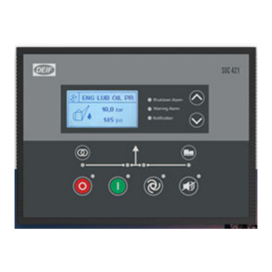
- Page 1 SGC 421 Single Genset Controller User manual...
-
Page 2: Table Of Contents
1. Introduction 1.1 About ................................................... 1.2 Function overview ............................................. 1.3 About the User manual ........................................... 1.3.1 General purpose ..........................................1.3.2 Software versions ..........................................1.4 Warnings and safety ..........................................1.4.1 Symbols for hazard statements ....................................1.4.2 Symbols for general notes ......................................1.4.3 Electrical safety .......................................... - Page 3 3.5.10 Rotary actuator ..........................................3.5.11 Display filter ............................................. 3.5.12 Password ID ............................................ 3.6 Passwords ..............................................4. Modes of operation 4.1 Operation mode ............................................4.2 AUTO mode ..............................................4.2.1 Island ..............................................4.2.2 Engine drive ............................................4.2.3 Automatic mains failure (AMF) ....................................4.2.4 Site battery monitoring .......................................
- Page 4 8. CAN bus engine communication 8.1 Overview ................................................ 8.1.1 About ............................................... 8.1.2 Default settings ..........................................8.1.3 Supported engines .......................................... 8.1.4 Engine values on the display ....................................8.2 Engine communication settings ....................................8.3 Generic J1939 ............................................9. Inputs and outputs 9.1 Digital inputs ...............................................
-
Page 5: Introduction
About The SGC 421 controller contains all the functions needed to protect and control the genset, the genset breaker, and a mains breaker. The values and alarms are shown on the LCD display screen, and operators can control the system from the display. -
Page 6: About The User Manual
• Event log for 100 events with real-time clock stamps • Fuel theft alarm Electronic governing The SGC 421 can do electronic governing for engines with mechanical fuel systems when you have installed a rotary actuator. About the User manual 1.3.1... -
Page 7: Electrical Safety
DEIF A/S reserves the right to change any of the contents of this document without prior notice. The English version of this document always contains the most recent and up-to-date information about the product. DEIF does not take responsibility for the accuracy of translations, and translations might not be updated at the same time as the English document. -
Page 8: Installation
2. Installation Dimensions Dimensions Length: 233.0 mm (9.17 in) Dimensions Height: 173.0 mm (6.81 in) Depth: 38.5 mm (1.52 in) Length: 219.0 mm (8.62 in) Panel cut-out Height: 158.0 mm (6.22 in) Tolerance: ± 0.3 mm (0.01 in) Tools and materials Tools required for mounting Tool Used for... -
Page 9: Mounting
NOTICE Too much torque damages the screw clamps and/or controller housing Do not use power tools during the installation. Materials required for mounting and wiring Materials Used for Four screw clamps Mounting the controller in the front panel Wires and connectors Wiring third party equipment to the controller terminals Cable ties Securing wiring... -
Page 10: Terminals
Terminals Terminal Text Description Connector Power ground BATT + Power supply positive DIG OUT A DC output - A DIG OUT B DC output - B DIG OUT C DC output - C BCP-508-10GN DIG OUT D DC output - D DIG OUT E DC output - E DIG OUT F... - Page 11 Terminal Text Description Connector E-GOV 1 Output for actuator E-GOV 4 Output for actuator BCP-508-4GN E-GOV 3 Output for actuator E-GOV 2 Output for actuator Analogue input auxiliary 0-5 V ANLG AUX 3/DIG 0 4-20 mA (LOP) Digital input O Input from engine speed sensor (inductive) Analogue input auxiliary BCP-508-5GN...
-
Page 12: Wiring
Terminal Text Description Connector MAINS V N Voltage input from mains neutral MAINS V L3 Voltage input from mains phase L3 MAINS V L2 Voltage input from mains phase L2 MAINS V L1 Voltage input from mains phase L1 BCP-508-7GN-4PA GEN V N Voltage input from gen neutral GEN V L3... -
Page 13: Wiring Guidelines - Best Practice For Grounding
Communication Communication ports for CAN (terminals 58 and 59) and RS-485 (terminals 31 and 32) have built-in 120 Ω termination resistors. Digital outputs If a digital output is connected to a relay, the relay must include freewheeling diodes. 2.5.2 Wiring guidelines - best practice for grounding It is important to follow these wiring guidelines to get: •... -
Page 14: Analogue Inputs
2.5.3 Analogue inputs Resistive sensor inputs Wiring for the sensor common point (SCP) for analogue inputs 1 to 3 (terminals 11 to 13). Wiring for the sensor common point (SCP) for analogue input 2 (terminal 12) when you use it as Fuel level sensor with reference to Battery Negative. -
Page 15: Ac Connections
Settings: • Polarity: Close to activate • SW state: Not activated • Logic status: Low 2.5.4 AC connections Three-phase application (4 wires) User manual 4189341355A EN Page 15 of 92... - Page 16 Three-phase application (3 wires) Two-phase application L1/L2 (3 wires) Two-phase application L1/L3 (3 wires) User manual 4189341355A EN Page 16 of 92...
-
Page 17: Rotary Actuator Outputs
Single-phase application (2 wires) Split phase application L1/L2 (3 wires) Split phase application L1/L3 (3 wires) 2.5.5 Rotary actuator outputs The actuator outputs are used when a 4-wired rotary actuator is installed in your application. The integrated electronic governor in the SGC controller is used together with the actuator to create an electronic governing application for mechanical fuel engines. -
Page 18: Current Transformer (Ct) Ground
Actuator connector outputs SGC outputs • ACT 1 is output terminal 17 • ACT 2 is output terminal 18 • ACT 3 is output terminal 19 • ACT 4 is output terminal 20 2.5.6 Current transformer (CT) ground Use one of these methods for the CT ground (S2) connections: 1. -
Page 19: Display And Menus
3. Display and menus Display, buttons, and LEDs Name Function Display Graphical Mains breaker Push to open or close the mains breaker. Stops the genset if manual mode is selected. The controller opens the genset breaker, and Stop the cooling down time starts. If you push the Stop button twice the engine stops immediately. -
Page 20: Display Settings
Display settings 3.2.1 Display To adjust for ambient lighting, configure the display settings. Use the smart connect software to configure the contrast in Module > Display > Contrast. You can also configure the time for when the page on the display changes in Timers > General > Screen Changeover Time. Parameter Range Default... -
Page 21: Load Histogram
Examples of display views 3.3.1 Load histogram The load histogram shows the engine running hours. The running hours are put into load groups. Use the histogram to monitor how long the genset operates at a specific load percentage. The load percentage is calculated using these parameters: •... -
Page 22: Auto Config Exit Mode
4. The display shows this screen: PASSWORD 5. Enter the password: • Use the Up and Down buttons to change the number. • Select a number with the Start button. 6. You can now configure the parameter. 7. To leave the configuration menu, push and hold the Stop/Config button. - Page 23 Parameter Range Default Description (AUTO CLEAR have resolved the condition that activated the WARNINGS) alarm. Language English You can change the display language if the (LANGUAGE English Chinese controller supports multiple languages. SUPPORT) Display (DISPLAY) Parameter Range Default Description Contrast Configure the display contrast with this 0 to 100 % 80 %...
- Page 24 Parameter Range Default Description (LOW BATT MON DELAY) During a site battery failure, the genset Genset Run Duration 1 to 720 minutes 270 minutes operates for the Genset Run duration. This is (GEN RUN DURATION) only for AUTO mode. Cyclic Mode (CYCLIC CONFIG) Parameter Range Default...
-
Page 25: Digital Inputs
Parameter Range Default Description Start Time 00:00 to 23:59 hours 09:59 hours Configure the start time for the sequences. (START TIME) Duration 00 hr 01 min. to 99 hr Configure for how long the genset operates 10 hours, 10 minutes (GEN ON DURATION) 59 min. - Page 26 Parameter Range Default Description Lube Oil Pressure See Digital input (Digital) Source source selection in Not used Select the source from the list. ((DIG) SOURCE) this document Name Auxiliary Input J You can configure the name of the input. (NAME) (Digital) Polarity Close to Activate Close to Activate...
- Page 27 Parameter Range Default Description Always (Digital) Activation If the input is active when the timer expires, the Delay 1 to 180 s controller actives the action for the digital input. ((DIG) ACTIVATION DELAY) If this parameter is enabled, the controller shuts (FLS) Low Fuel Level Enable down the engine when the fuel level is less than...
- Page 28 Parameter Range Default Description Name Auxiliary Input L You can configure the name of the input. (NAME) (Digital) Polarity Close to Activate Close to Activate Select the polarity for the input. ((DIG) POLARITY) Open to Activate None Notification (Digital) Action Warning None Select the action when the input is activated.
- Page 29 Parameter Range Default Description (Digital) Activation If the input is active when the timer expires, the Delay 1 to 180 s controller actives the action for the digital input. ((DIG) ACTIVATION DELAY) If this parameter is enabled, the controller shuts (S1) Shutdown Enable Not enabled...
- Page 30 Parameter Range Default Description S2 Sensor See Digital input (Digital) Source source selection in Not used Select the source from the list. ((DIG) SOURCE) this document Name Auxiliary Input N You can configure the name of the input. (NAME) (Digital) Polarity Close to Activate Close to Activate Select the polarity for the input.
- Page 31 Parameter Range Default Description 0 to 5 V Sensor See Digital input (Digital) Source source selection in Not used Select the source from the list. ((DIG) SOURCE) this document Name Auxiliary Input O You can configure the name of the input. (NAME) (Digital) Polarity Close to Activate...
- Page 32 Parameter Range Default Description (0-5 V) Warning Enable The controller activates a warming alarm when Not enabled (WARNING) Disable this parameter is enabled. (0-5 V) Warning If the monitored value is more than or less than Threshold 0.0 to 1000.0 this set point, the controller activates a warning (WARNING alarm.
- Page 33 Parameter Range Default Description (4-20 mA) Warning Enable The controller activates a warming alarm when Not enabled (WARNING) Disable this parameter is enabled. (4-20 mA) Warning If the monitored value is more than or less than Threshold 0.0 to 1000.0 this set point, the controller activates a warning (WARNING alarm.
-
Page 34: Outputs
3.5.4 Outputs Outputs # (OUT #) Parameter Range Default Description See Digital output Source source selection in Select an output source from the list. (SOURCE) this document Select what the status of the output source is On Activation Energise De-energise when it is active. -
Page 35: Generator
General (GENERAL TIMER) Parameter Range Default Description Power Save Mode Delay If the controller is not in use, the backlight turns 5 to 1800 s 30 s (PWR SAVE MODE off when the timer expires. DELAY) Screen Changeover Time The display page changes when the timer 1 to 1800 s (SCRN CHNGOVER expires. - Page 36 Parameter Range Default Description None Phase Reversal Action Notification Configure the action for phase reversal (PHASE REVERSAL Warning None detection. ACTION) Electrical Trip Shutdown If this parameter is enabled, the load is Auto Load Transfer automatically transferred to the genset when Enable (AUTO LOAD Enabled...
- Page 37 Voltage Monitoring (VOLT MONITOR) Parameter Range Default Description Under-voltage If this parameter is enabled, the controller shuts Shutdown Enable Not enabled down the engine when the voltage is less than (UNDER VOLT Disable the configured set point for under-voltage. SHUTDOWN) Under-voltage Shutdown Threshold 10 to 195 V phase-...
- Page 38 Frequency Monitoring (FREQ MONITOR) Parameter Range Default Description Under-frequency If this parameter is enabled, the controller shuts Shutdown Enable down the engine when the frequency is less Not enabled (UNDER FREQ Disable than the configured set point for under- SHUTDOWN) frequency.
- Page 39 Current Monitoring (CURRENT MONITOR) Parameter Range Default Description CT Ratio 0 to 8000 / 5 150/5 CT ratio. (LOAD CT RATIO) None Notification Over-current Action Warning None Configure the action for over-current. (OVER CURR ACTION) Electrical Trip Shutdown Over-current Threshold The action for over-current is activated when 10 to 200 A (OVER CURR...
-
Page 40: Mains
Parameter Range Default Description Electrical Trip Shutdown Overload Threshold The action for overload is activated when the (OVERLOAD 10 to 200 % 90 % load is more than this set point. THRESHOLD) Overload Monitoring If the load is more than the set point for Delay 1 to 600 s overload when the time expires, the action for... - Page 41 Parameter Range Default Description Phase Reversal Action None Configure the action for phase reversal (PHASE REVERSAL None Notification detection. ACTION) Partial Healthy If this parameter is enabled, a mains failure is Detection Enable Not enabled not detected if one or two of the phases fail. (MAINS PARTIAL Disable This is only for a 3-phase system.
-
Page 42: Engine
Parameter Range Default Description (OF) Trip If the mains frequency is more than this set 26.0 to 75.0 Hz 55 Hz (OF TRIP) point, there is a mains failure. (OF) Return The mains returns when the mains frequency is 25.0 to 74.0 Hz 52 Hz (OF RETURN) less than this set point. - Page 43 Parameter Range Default Description (CHG ALT THRESHOLD) Speed Monitoring (SPEED MONITOR) Parameter Range Default Description Engine Speed Sense Alternator frequency Source Magnetic Pickup Alternator frequency Configure how engine speed is monitored. (SPEED SENSE W-Point Frequency SOURCE) Flywheel Teeth 1 to 300 The number of teeth on the flywheel.
- Page 44 Battery Monitoring (BATTERY MONITOR) Parameter Range Default Description None Low Battery Voltage Notification Configure the action for when the battery Action Warning None voltage is low. (LOW VOLT ACTION) Electrical Trip Shutdown Low Battery Voltage The action for low battery voltage is activated Threshold 8.0 to 31.0 V 8.0 V...
- Page 45 Parameter Range Default Description temperature is more than the set point for the coolant temperature (ENG TEMP LIMIT). Engine Coolant Temp The set point for the engine coolant Threshold 10 to 300 °C 25 °C temperature. (ENG TEMP LIMIT) Coolant Control Parameter Range Default...
- Page 46 Parameter Range Default Description Deutz - EMR KUBOTA Weichai Hatz PERKINS ADEM4 Yuchai YCGCU ECU Cummins Yuchai Bosch Measurements from the ECU Enable Lube Oil Pressure Not enabled Read and monitor the lube oil pressure. Disable Enable Coolant Temperature Not enabled Read and monitor the coolant temperature.
- Page 47 Parameter Range Default Description SGC Source Address 0 to 253 Source address for the SGC. ECU Source Address 0 to 253 Source address for the ECU. ECU Diagnostic Lamps (Amber, Red, Malfunction, Protect) None Notification Configure the action for the ECU diagnostics Action Warning None...
-
Page 48: Maintenance
3.5.9 Maintenance Maintenance (MAINT ALARM) Parameter Range Default Description Alarm Action Notification Notification Configure the alarm action for maintenance. (ACTION) Warning Due At Engine Hours The maintenance timer is based on running (DUE AT ENGINE 10 to 65000 hours 250 hours hours. -
Page 49: Display Filter
Parameter Range Default Description Load Based Droop This is only for load based droop. Select the Droop 0 to 4 % percentage droop. Target Speed 500 to 4000 RPM 500 RPM Target output speed for the engine. Proportional gain for the engine speed Proportional Gain (Kp) 0 to 1000 governor. -
Page 50: Passwords
Parameter Input Range Description Letters: A to Z (PASSWORD 1) #### Numbers: 0 to 9 The password for level 1 access. (PASSWORD 2) #### Numbers: 0 to 9 The password for level 2 access. Passwords The controller is protected from set-up changes with a four digit password. There are two password levels: Level Access... -
Page 51: Modes Of Operation
4. Modes of operation Operation mode The controller has two running modes: • AUTO: The controller operates automatically, and the operator cannot initiate sequences manually. • Manual: The operator has to initiate all sequences. You can do this with the buttons, Modbus commands, or digital inputs. -
Page 52: Engine Drive
4.2.2 Engine drive You can use the SGC to control one engine. The controller has all the necessary functions to control and protect an engine. To use the controller to control an engine drive, go to Generator > Alternator Configuration in the smart connect software. - Page 53 In the smart connect software, go to Mains > Configuration > Mains monitoring and make sure that mains monitoring is enabled. Go to Module in the smart connect software, to make sure that auto exercise, cyclic mode, and site battery monitoring is not enabled. The SGC controller can automatically start the genset and switch to generator supply if there is a mains failure (see the flowchart above).
-
Page 54: Site Battery Monitoring
Minimum voltage and frequency set points Generator > Alternator Configuration Parameter Range Default Min Healthy Voltage 10 to 100 % 40 % Min Healthy Frequency 10 to 100 % 40 % 4.2.4 Site battery monitoring Use this function to monitor the site battery and the shelter temperature. The SGC controls the power sources (mains or genset) to keep the battery charge within the configured set points. - Page 55 operates until the timer for the site battery expires. If the genset starts as a response to the condition of the shelter temperature, then the genset operates until the timer for the shelter temperature expires. If the shelter temperature is more than the high shelter temp set point when the timer expires, the DG run duration timer starts again.
-
Page 56: Cyclic Mode
Parameter Range Default Description timer expires, the controller activates the start sequence for the genset. The genset operates for this time Shelt Temp Run Duration 0 to 720 min 60 min duration when the shelter temperature is too high. Timers Timers >... - Page 57 During normal operations, the mains supplies the load. If there is a mains failure, the controller automatically starts the genset and switch to generator supply (see the flowchart above). Once the genset loading voltage and frequency are more than their minimum set points, the Warm-up delay timer starts. When the Warm-up delay timer expires, the timer for the load transfer delay starts, and the genset breaker closes.
-
Page 58: Remote Start/Stop
4.2.6 Remote start/stop You can configure digital inputs as remote start/stop inputs (latched type input). You can start and stop the genset remotely by activating the configured remote start/stop inputs. To configure the remote start/stop inputs, go to Digital Inputs in the smart connect software and select the source as Remote Start/Stop. -
Page 59: Auto Exercise
Timers Timers > Start/Stop Parameter Range Default Warm-Up Delay 0 to 60 s Load Transfer Delay 1 to 60 s 4.2.7 Auto exercise You can use exercise mode to schedule a maximum of two start/stop sequences for the genset. The sequences can occur daily, weekly, or monthly. -
Page 60: Manual Mode
Manual mode In manual mode, the operator must start all sequences. You can do this with the display buttons, Modbus commands, or digital inputs. Commands in manual mode Command Description The start sequence is started and continues until the genset starts or the maximum Start number of starts attempts is reached. -
Page 61: Test Mode
Command Description The controller ramps down and opens the generator breaker at the breaker open point if Open the genset breaker the mains breaker is closed. The controller opens the generator breaker instantly if the mains breaker is open or the controller is in island mode. Acknowledge alarms Push the acknowledge button to acknowledge an alarm in manual and AUTO mode. -
Page 62: General Functions
5. General functions AC measurement systems The AC system can be three-phase, two-phase, single-phase, or split phase. CAUTION Incorrect configuration is dangerous Configure the correct AC configuration. If in doubt, contact the switchboard manufacturer for information. Nominal settings 5.2.1 Default nominal settings Text Range Default... -
Page 63: Breakers
Text Range Default Note Check the minimum and maximum values the SGC Nominal load current 0 to 8000 A 350 A can read and display. Remember to include the Check the minimum and maximum values the SGC Nominal 4th CT current 0 to 8000 A 800 A can read and display. -
Page 64: Load Calculations
Timers > General Parameter Range Default Breaker Close Delay 0.1 to 30 s Load calculations For automatic mains failure (AMF) applications, you can place the current transformer (CT) on the line from the genset or on the load cable. The load calculations are based on where the CT is placed. If the location of the CT is on the On Alt Output cable, which means the CT is on the genset side, then the load calculations are based on the genset load. - Page 65 Alarms and their causes Alarms Causes/Indication Actions The measured oil pressure is less than the configured Shutdown Low Oil Pressure (Sensor) value. Warning Shutdown Warning Low Oil Pressure (Switch) The switch has measured a low oil pressure. Electrical Trip Notification The measured fuel level is less than the configured Shutdown Low Fuel level (Sensor)
- Page 66 Alarms Causes/Indication Actions Emergency stop is activated. Emergency Stop Shutdown The emergency stop is configured as a digital input, and the input has triggered for longer than the configured time. Shutdown The charge alternator voltage is less than the Warning Charge Fail configured value.
- Page 67 Alarms Causes/Indication Actions Shutdown Warning DG Phase Reversal Alternator phase sequence (L1-L2-L3) is not correct. Electrical Trip Notification Mains Phase Reversal Error during mains operation. Notification Shutdown LOP/Ckt Open (terminal The oil pressure sensor on terminal 26 is not detected Warning (circuit open).
- Page 68 Alarms Causes/Indication Actions Shutdown Breaker close failure. Unable to close the genset Warning Fail To Close Gen Output breaker. Electrical Trip Notification Shutdown Fail To Close Mains Breaker close failure. Unable to close the mains Warning Output breaker. Electrical Trip Notification Shutdown Breaker close failure.
-
Page 69: Engine Functions
6. Engine functions Engine sequences The engine start and stop sequences are started automatically if AUTO mode is selected. In manual mode, the operator has to initiate the sequences. Engine start functions 6.2.1 Start sequence The following drawing shows the start sequence of the genset. Configure the run coil timer to activate the fuel relay output and the idle mode output before pre-heat is completed. - Page 70 Timers > General Parameter Range Default Safety Monitoring Delay 10 to 60 s 10 s Warm-Up Delay 0 to 60 s ISV Pull Signal Timer 0.1 s Engine Engine > Preheat Parameter Range Default Preheat Timer 0 to 1200 s 10 s Engine >...
- Page 71 Start sequence flowchart 1. The controller sends a start signal to the genset. 2. The Start Delay timer is activated. 3. When the Start Delay timer expires, the pre-heating function is activated if this is configured. If pre-heating is not configured, go to step 7 (crank hold). 4.
-
Page 72: Engine Stop Functions
Engine stop functions 6.3.1 Stop sequence The stop sequence is activated if a stop command is given. The stop sequence includes the cooling down time if the stop is a normal or controlled stop. Timers > General Parameter Range Default Engine Cooling Time 0 to 300 s Stop Action... -
Page 73: Stop Sequence Flowchart
6.3.2 Stop sequence flowchart 1. The genset breaker opens if there is a breaker in the application. 2. A stop command is given. You can activate the command with a digital input or Modbus. You can only use the display buttons in manual mode. 3. -
Page 74: Idle Mode
Idle mode The purpose of the idle mode function is to allow the engine to operate at idle speed before ramping up to rated speed. You can activate idle mode using a digital input or a timer. If you have configured an input and a timer for idle mode, then the timer is overruled. -
Page 75: Coolant Temperature
Stop sequence for idle mode You can also activate idle mode during the stop sequence. Go to Engine > Speed Monitoring > Stopping Idle Time to configure the timer for the idle stop time. If you set the timer to 0 seconds, idle mode is not activated during the stop sequence. - Page 76 3. Go to the Outputs tab and select the output you want to use. 4. Use the drop-down list next to the output to select Coolant Heater Control Output as the source. 5. Go to the Engine tab and select Coolant Control. 6.
-
Page 77: Engine Pre-Heater
Engine pre-heater This function is used to control the temperature of the engine before the engine starts. The function is only active when the engine is stopped. A temperature sensor is used to activate an external heating system to keep the engine at a minimum temperature. -
Page 78: Other Functions
Parameter Range Default Description for the engine temperature (Engine Coolant Temp Threshold). Engine Coolant Temp The coolant temperature the engine must reach 10 to 300 °C 25 °C Threshold during pre-heat. Other functions 6.7.1 Maintenance timer The controller has one timer to monitor maintenance intervals. The timer function is based on engine running hours or a due date. - Page 79 Engine stop Cooling down Extended stop Keyswitch output User manual 4189341355A EN Page 79 of 92...
-
Page 80: Modbus
For more information about Modbus in general and the Modbus protocol, refer to the documentation freely available at http://www.modbus.org. Refer to the Modbus tables, available for download at www.deif.com, to see how the controller data is mapped to the Modbus addresses. -
Page 81: Can Bus Engine Communication
NOTE See the ECU user manuals for the ECU protocol technical description and details of each communication value. Other engines and controllers For engines and controllers not listed in this document, contact DEIF. 8.1.2 Default settings The SGC controller is delivered with a set of default settings for engine communication. These settings are not necessarily correct for your engine or genset. -
Page 82: Engine Values On The Display
Engine communication settings Use the DEIF smart connect software to configure engine communication for the SGC controller. Open DEIF smart connect and connect to the SGC controller. Select Start > Engine > Engine Control unit (ECU) to see the engine communication settings. -
Page 83: Generic J1939
See the specific documentation for the engine/ECU for information about the source address. Generic J1939 Basic information • Engine controller/type: A controller that uses generic J1939. • DEIF smart connect: Select Generic J1939. • Complies with the J1939 standard. • Baud rate: 250 kb/s Warnings and shutdowns These standard warnings and shutdowns are supported: •... - Page 84 • Use the Up and Down buttons to go through the alarm list. • oc##: Shows how many times a specific alarm has occurred. • CLRALL: Push ENTER to clear the entire alarm log list. For safety reasons, this requires the master password. NOTE If the controller has no translation text for an SPN diagnostic number, Text N/A is shown.
-
Page 85: Inputs And Outputs
9. Inputs and outputs Digital inputs Source Description Not used The digital input is not used. User configured The digital input is configured by the user. The input is activated when the fuel level is less than the configured value. Low fuel level switch The configured alarm is shown. -
Page 86: Digital Outputs
Source Description • Mains monitoring is enabled and there is a mains failure. The input is deactivated. The is still a mains failure and the mains breaker opens. When this input is activated an alarm is shown on the display. You can V-belt broken switch configure the alarm type. - Page 87 Output source Description This output is activated when the digital input for close mains/open genset Close mains contactor is activated in manual mode. Mains failure This output is activated when there is a mains failure. Common alarm This output is activated when one of the alarm types is activated. Common electrical trip This output is activated when there is an active electrical trip alarm.
- Page 88 Output source Description This output is activated when the over-voltage shutdown alarm for phase L3 phase OV shutdown L3 is activated. This output is activated when the under-voltage shutdown alarm for phase L3 Phase UV Shutdown L3 is activated. This output is activated when the controller shuts down the genset Gen over current because of over-current.
- Page 89 Output source Description Fail to close generator This output is activated when there is a genset breaker failure. Fail to close mains This output is activated when there is a mains breaker failure. This output is activated when the loading voltage has not reached the Loading volt not reached minimum set point during the start sequence.
-
Page 90: Troubleshooting
10. Troubleshooting General troubleshooting Fault Action • Check the battery voltage. • Check the fuse on the battery supply. The controller does not power ON. • Check continuity between battery positive and controller terminal 2. • Check continuity between battery ground and controller terminal 1. The controller display is not •... - Page 91 Fault Action • Check start-relay connection to the terminal on the controller. • Go to the configuration menu on the controller. Make sure the start mode and start relay output polarity are configured correctly. • Check the alternator voltage signal (L1 phase) is received by the controller terminal.
- Page 92 Site battery monitoring troubleshooting Fault Action • Make sure the panel and site are correctly earthed. The site voltage is not consistent • Make sure the connections are wired correctly (terminals 24 and 25). User manual 4189341355A EN Page 92 of 92...
Need help?
Do you have a question about the SGC 421 and is the answer not in the manual?
Questions and answers