Deif CGC 400 Operator's Manual
Compact genset controller
Hide thumbs
Also See for CGC 400:
- Installation instructions manual (25 pages) ,
- Quick start manual (10 pages) ,
- Reference book (96 pages)
Table of Contents
Advertisement
OPERATOR'S MANUAL
Compact Genset Controller, CGC 400
● Push-buttons
● LEDs
● Display and menu structure
● Display readings
● Alarm handling and log list
DEIF A/S · Frisenborgvej 33 · DK-7800 Skive · Tel.: +45 9614 9614 · Fax: +45 9614 9615 · info@deif.com · www.deif.com
Document no.: 4189340787A
SW version: 1.00
Advertisement
Table of Contents

Related Manuals for Deif CGC 400


Summary of Contents for Deif CGC 400
- Page 1 ● Alarm handling and log list DEIF A/S · Frisenborgvej 33 · DK-7800 Skive · Tel.: +45 9614 9614 · Fax: +45 9614 9615 · info@deif.com · www.deif.com isenborgvej 33 · DK-7800 Skive · Tel.: +45 9614 9614 · Fax: +45 9614 9615 · info@deif.com · www.deif.com Document no.: 4189340787A...
-
Page 2: Table Of Contents
CGC 400 Operator's manual 4189340787 1. General information 1.1. Warnings, legal information and safety....................3 1.1.1. Warnings and notes ........................3 1.1.2. Legal information and disclaimer ....................3 1.1.3. Safety issues ..........................3 1.1.4. Electrostatic discharge awareness ....................3 1.1.5. Factory settings ..........................4 1.2. About the operator's manual........................4 1.2.1. -
Page 3: General Information
1.1.2 Legal information and disclaimer DEIF takes no responsibility for installation or operation of the generator set. If there is any doubt about how to install or operate the engine/generator controlled by the unit, the company responsible for the installation or the operation of the set must be contacted. -
Page 4: Factory Settings
CGC 400 Operator's manual 4189340787 General information 1.1.5 Factory settings The unit is delivered from factory with certain factory settings. These are based on average values and are not necessarily the correct settings for matching the engine/generator set in question. Precautions must be taken to check the settings before running the engine/generator set. -
Page 5: Push-Buttons And Leds
CGC 400 Operator's manual 4189340787 Push-buttons and LEDs 2. Push-buttons and LEDs 2.1 Push-button functions The push-buttons on the unit have the following functions: Function Secondary functionality Scroll the display up once Programming: Increase setpoint value Scroll the display down once... -
Page 6: Led Functions
The display unit holds 10 LED functions. Dependent on the situation, the colour of the LEDs is green, red or a combination. The table below describes the functionality of the LEDs on the CGC 400: LED no. LED name LED function... -
Page 7: Display And Menu Structure
CGC 400 Operator's manual 4189340787 Display and menu structure 3. Display and menu structure 3.1 Menu 3.1.1 Menu system The display includes the menu systems listed below which can be used/viewed without password entry: View menu system: This is the commonly used menu system, which contains displaying of the measured values. -
Page 8: Menu Structure Example
CGC 400 Operator's manual 4189340787 Display and menu structure 3.1.3 Menu structure example The figure below is an example of how the menu structure is arranged, and it also shows the meaning of the entry symbols..(up to 20 views) -
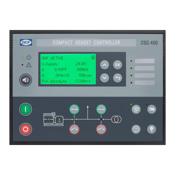
Page 9: Display Functions
CGC 400 Operator's manual 4189340787 Display and menu structure 3.2 Display functions 3.2.1 Functional examples The display indicates both readings and alarms. The examples below are with icons and English language. View examples Service menu Appl. Ver.: 9.90.0 The software version can be found in the Service menu Appl. - Page 10 CGC 400 Operator's manual 4189340787 Display and menu structure Edit value with up and down arrows and save the value by pressing the 1000 -P> OK button. Set point: -5.0% Timer: 0.5 sec Output A: Not used Output B: Not used For detailed information about changing parameters and setup, please see the Designer's Ref- erence Handbook.
-
Page 11: Status Line Text
CGC 400 Operator's manual 4189340787 Status line text 4. Status line text 4.1 Status line text 4.1.1 Standard texts Condition Comment BLOCK Block mode is activated SIMPLE TEST Test mode is activated FULL TEST SIMPLE TEST ###.#min Test mode activated and test timer counting down FULL TEST ###.#min... - Page 12 CGC 400 Operator's manual 4189340787 Status line text Condition Comment START RELAY OFF The start relay is deactivated during the start se- quence MAINS FAILURE Mains failure and mains failure timer expired MAINS FAILURE IN ###s Frequency or voltage measurement is outside the lim-...
-
Page 13: Running Modes
CGC 400 Operator's manual 4189340787 Running modes 5. Running modes 5.1 Running mode overview The unit has four different running modes and one block mode. The different running modes are selected via the display or the PC utility software. For detailed information please see Designer's Reference Handbook. -
Page 14: Alarm Handling And Log List
CGC 400 Operator's manual 4189340787 Alarm handling and log list 6. Alarm handling and log list 6.1 Alarm handling When an alarm occurs, the unit will automatically go to the alarm list for display of the alarm. If reading of the alarms is not desired, use the BACK push-button to exit the alarm list.
Need help?
Do you have a question about the CGC 400 and is the answer not in the manual?
Questions and answers