Deif AGC 200 Operator's Manual
Advanced genset controller
Hide thumbs
Also See for AGC 200:
- Installation instructions manual (67 pages) ,
- Operator's manual (25 pages) ,
- General manuallines for commissioning (25 pages)
Table of Contents
Advertisement
Advertisement
Table of Contents

Related Manuals for Deif AGC 200


Summary of Contents for Deif AGC 200
- Page 1 ● Log list DEIF A/S · Frisenborgvej 33 · DK-7800 Skive · Tel.: +45 9614 9614 · Fax: +45 9614 9615 · info@deif.com · www.deif.com isenborgvej 33 · DK-7800 Skive · Tel.: +45 9614 9614 · Fax: +45 9614 9615 · info@deif.com · www.deif.com Document no.: 4189340607E...
-
Page 2: Table Of Contents
AGC 200 operators manual 4189340607 1. General information 1.1. Warnings, legal information and safety....................3 1.1.1. Warnings and notes ........................3 1.1.2. Legal information and disclaimer ....................3 1.1.3. Safety issues ..........................3 1.1.4. Electrostatic discharge awareness ....................3 1.1.5. Factory settings ..........................3 1.2. -
Page 3: General Information
1.1.2 Legal information and disclaimer DEIF takes no responsibility for installation or operation of the generator set. If there is any doubt about how to install or operate the engine/generator controlled by the Multi-line 2 unit, the company responsible for the installation or the operation of the set must be contacted. -
Page 4: About The Operator's Manual
AGC 200 operators manual 4189340607 General information 1.2 About the operator's manual 1.2.1 General purpose This Operator's Manual mainly includes general product information, display readings, push-button and LED functions, alarm handling descriptions and presentation of the log list. The general purpose of this document is to give the operator important information to be used in the daily operation of the unit. -
Page 5: Agc 200 Variants
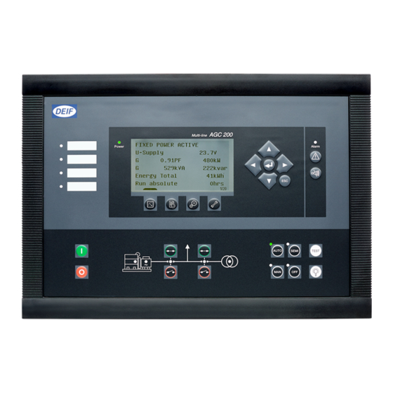
AGC 200 operators manual 4189340607 AGC 200 variants 2. AGC 200 variants 2.1 Front views 2.1.1 Island, AGC 212/222/232/242 DEIF A/S Page 5 of 21... -
Page 6: Automatic Mains Failure, Agc 213/233/243
AGC 200 operators manual 4189340607 AGC 200 variants 2.1.2 Automatic mains failure, AGC 213/233/243 DEIF A/S Page 6 of 21... -
Page 7: Mains, Agc 245
AGC 200 operators manual 4189340607 AGC 200 variants 2.1.3 Mains, AGC 245 DEIF A/S Page 7 of 21... -
Page 8: Mains And Tie Breaker, Agc 246
AGC 200 operators manual 4189340607 AGC 200 variants 2.1.4 Mains and tie breaker, AGC 246 DEIF A/S Page 8 of 21... -
Page 9: Bus Tie Breaker, Agc 244
AGC 200 operators manual 4189340607 AGC 200 variants 2.1.5 Bus tie breaker, AGC 244 DEIF A/S Page 9 of 21... -
Page 10: Display, Push-Buttons And Leds
AGC 200 operators manual 4189340607 Display, push-buttons and LEDs 3. Display, push-buttons and LEDs 3.1 Push-buttons functions The display unit holds a number of push-button functions which are described below: 1. View of measured values 2. Log lists. The list holds 150 events. These events are deleted when the AGC is switched off 3. -
Page 11: Led Functions
AGC 200 operators manual 4189340607 Display, push-buttons and LEDs 3.2 LED functions The display unit holds 10 LED functions. The colour is green or red or a combination in different situations. The display LEDs are indicating as follows: 1. User-configurable LED 2. -
Page 12: Display And Menu Structure
AGC 200 operators manual 4189340607 Display and menu structure 4. Display and menu structure 4.1 About display and menu structures 4.1.1 LCD display The display is a backlit LCD graphical display. The display light intensity, LED indication and contrast can be adjusted from menu 9150. - Page 13 AGC 200 operators manual 4189340607 Display and menu structure MAINS FAILURE U-supply 24.1 V 0.001 PF 0 kW 0 kVA 0 kVAr Energy Total 0 kWh Run Absolute 0 hrs 1/20 In the view menus, various measured values are on display. The views contain up to 20 different windows which can be selected using the push-buttons located on the right hand side of the display.
-
Page 14: Status Line Text
AGC 200 operators manual 4189340607 Display and menu structure 4.1.5 Status line text This table explains the different messages. Status text Condition Comment BLOCK Block mode is activated SIMPLE TEST Test mode is activated LOAD TEST FULL TEST SIMPLE TEST ###.#min... - Page 15 AGC 200 operators manual 4189340607 Display and menu structure Status text Condition Comment SHUTDOWN OVERRIDE The configurable input is active ACCESS LOCK The configurable input is activated, and the operator tries to activate one of the blocked keys GB TRIP EXTERNALLY...
- Page 16 AGC 24x only MOUNT CAN CONNECTOR Connect the power management CAN line AGC 24x only ADAPT IN PROGRESS The AGC 200 is receiving the application that AGC 24x only it has just been connected to DEIF A/S Page 16 of 21...
- Page 17 AGC 200 operators manual 4189340607 Display and menu structure Status text Condition Comment SETUP IN PROGRESS The new AGC is being added to the existing AGC 24x only application SETUP COMPLETED Successful update of the application in all AGC 24x only...
- Page 18 AGC 200 operators manual 4189340607 Display and menu structure Texts only related to power management (AGC 24x and 22xvariants only) Status text Condition Comment DG unit BLACKOUT ENABLE This information is shown if a CAN failure is present in a power management application...
- Page 19 AGC 200 operators manual 4189340607 Display and menu structure Status text Condition Comment RECEIVE ERROR Application is not received correctly View menu example MAINS FAILURE MAINS FAILURE MAINS FAILURE U-supply 24.1 V Event log Setup menu Press Press 0.001 PF...
-
Page 20: Running Modes
4.1.6 Running modes There are five buttons, located in the lower right corner of the AGC 200 display, which can be used to change the running mode. (Some controller types will have less than five buttons). The running mode is changed by pressing one of the buttons. -
Page 21: Alarm Handling And Log List
AGC 200 operators manual 4189340607 Alarm handling and log list 5. Alarm handling and log list 5.1 Alarm handling When an alarm occurs, the unit will automatically go to the alarm list, if selected (setting 6900 Alarm jump) for display of the alarm. If setting 6900 is OFF, you must press to enter the alarm list.
Need help?
Do you have a question about the AGC 200 and is the answer not in the manual?
Questions and answers