Endress+Hauser Proline Prosonic Flow B 200 Operating Instructions Manual
Ultrasonic transit time flowmeter
Hide thumbs
Also See for Proline Prosonic Flow B 200:
- Operating instructions manual (114 pages) ,
- Operating instructions manual (36 pages) ,
- Brief operating instructions (44 pages)
Table of Contents
Advertisement
BA01031D/06/EN/03.15
71283621
Valid as of version
01.02.zz (Device firmware)
AUTHORIZED DISTRIBUTOR:
InstrumentsAndControl.com
Houston, Texas USA
sales@InstrumentsAndControl.com
832-615-3588
Products
Operating Instructions
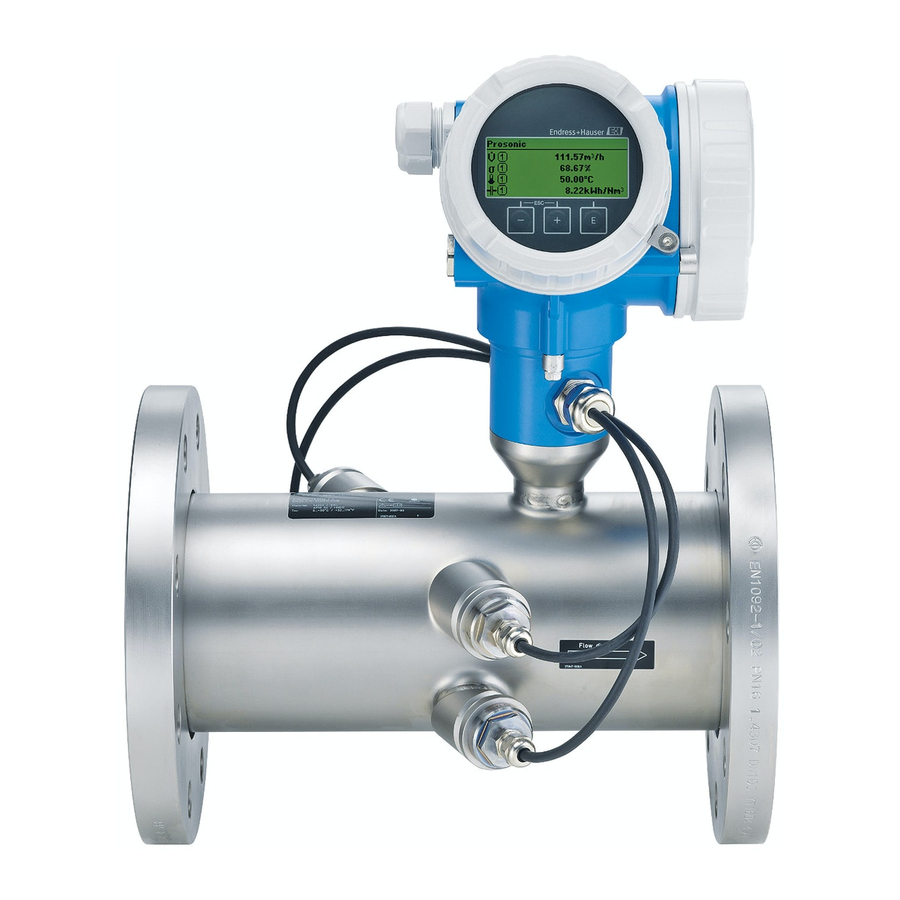
Proline Prosonic Flow B 200
HART
Ultrasonic transit time flowmeter
Solutions
Services
Advertisement
Table of Contents

Subscribe to Our Youtube Channel
Related Manuals for Endress+Hauser Proline Prosonic Flow B 200


Summary of Contents for Endress+Hauser Proline Prosonic Flow B 200
-
Page 1: Operating Instructions
Products Solutions Services BA01031D/06/EN/03.15 71283621 Valid as of version 01.02.zz (Device firmware) Operating Instructions Proline Prosonic Flow B 200 HART Ultrasonic transit time flowmeter AUTHORIZED DISTRIBUTOR: InstrumentsAndControl.com Houston, Texas USA sales@InstrumentsAndControl.com 832-615-3588... - Page 2 • The manufacturer reserves the right to modify technical data without prior notice. Your Endress+Hauser Sales Center will supply you with current information and updates to these instructions. Endress+Hauser...
-
Page 3: Table Of Contents
Proline Prosonic Flow B 200 HART Table of contents Table of contents 6.2.4 Turning the transmitter housing ..21 Document information ....6 6.2.5 Turning the display module . - Page 4 10.5 Advanced settings ..... 84 13.3 Endress+Hauser services ....123 10.5.1 Configuring the totalizer .
- Page 5 Proline Prosonic Flow B 200 HART Table of contents 16.14 Accessories ......147 16.15 Documentation ..... . 148 Index .
-
Page 6: Safety Symbols
Document information Proline Prosonic Flow B 200 HART Document information Document function These Operating Instructions contain all the information that is required in various phases of the life cycle of the device: from product identification, incoming acceptance and storage, to mounting, connection, operation and commissioning through to troubleshooting, maintenance and disposal. - Page 7 • The W@M Device Viewer : Enter the serial number from the nameplate (www.endress.com/deviceviewer) • The Endress+Hauser Operations App: Enter the serial number from the nameplate or scan the 2-D matrix code (QR code) on the nameplate. For a detailed list of the individual documents along with the documentation code →...
- Page 8 Registered trademarks ® HART Registered trademark of the HART Communication Foundation, Austin, USA Applicator ® , FieldCare ® , Field Xpert , HistoROM ® , Heartbeat Technology Registered or registration-pending trademarks of the Endress+Hauser Group Endress+Hauser...
-
Page 9: Basic Safety Instructions
Proline Prosonic Flow B 200 HART Basic safety instructions Basic safety instructions Requirements for the personnel The personnel for installation, commissioning, diagnostics and maintenance must fulfill the following requirements: ‣ Trained, qualified specialists must have a relevant qualification for this specific function and task ‣... - Page 10 Verification for borderline cases: ‣ For special fluids and fluids for cleaning, Endress+Hauser is glad to provide assistance in verifying the corrosion resistance of fluid-wetted materials, but does not accept any warranty or liability as minute changes in the temperature, concentration or level of contamination in the process can alter the corrosion resistance properties.
- Page 11 Proline Prosonic Flow B 200 HART Basic safety instructions IT security We only provide a warranty if the device is installed and used as described in the Operating Instructions. The device is equipped with security mechanisms to protect it against any inadvertent changes to the device settings.
-
Page 12: Product Description
Product description Proline Prosonic Flow B 200 HART Product description The device consists of a transmitter and a sensor. The device is available as a compact version: The transmitter and sensor form a mechanical unit. Product design A0016199 1... - Page 13 • If one of the conditions is not satisfied, contact your Endress+Hauser Sales Center. • Depending on the device version, the CD-ROM might not be part of the delivery! The Technical Documentation is available via the Internet or via the Endress+Hauser Operations App, see the "Product identification"...
- Page 14 "Supplementary device-dependent documentation" → 8 • The W@M Device Viewer: Enter the serial number from the nameplate (www.endress.com/deviceviewer) • The Endress+Hauser Operations App: Enter the serial number from the nameplate or scan the 2-D matrix code (QR code) on the nameplate. 4.2.1...
- Page 15 Proline Prosonic Flow B 200 HART Incoming acceptance and product identification 4.2.2 Sensor nameplate 3 4 5 Order code: Ser.No.: Ext. ord. cd.: ptest= pnom = PS = Materials: Date: A0016420 3 Example of 1st sensor nameplate Manufacturing location...
- Page 16 Storage and transport Proline Prosonic Flow B 200 HART Storage and transport Storage conditions Observe the following notes for storage: • Store in the original packaging to ensure protection from shock. • Do not remove protective covers or protective caps installed on process connections.
- Page 17 Proline Prosonic Flow B 200 HART Storage and transport 5.2.2 Measuring devices with lifting lugs CAUTION Special transportation instructions for devices with lifting lugs ‣ Only use the lifting lugs fitted on the device or flanges to transport the device.
- Page 18 Installation Proline Prosonic Flow B 200 HART Installation Installation conditions No special measures such as supports are necessary. External forces are absorbed by the construction of the device. 6.1.1 Mounting position Mounting location A0015543 Orientation The direction of the arrow on the sensor helps you to install the sensor according to the flow direction (direction of medium flow through the piping).
- Page 19 Proline Prosonic Flow B 200 HART Installation Orientation Compact version Horizontal orientation, transmitter head down * A0015590 Horizontal orientation, transmitter head at side A0015592 * A maximum deviation of only ±3° is permitted for the horizontal alignment of the converters.
- Page 20 Installation Proline Prosonic Flow B 200 HART Two-path version: DN 100 to 200 (4 to 8") 10 × DN 3 × DN 10 × DN 3 × DN 10 × DN 3 × DN 10 × DN 3 × DN A0015553 ...
- Page 21 Proline Prosonic Flow B 200 HART Installation Thermal insulation For optimum temperature and methane fraction measurement (order characteristic for "Sensor version", option 2 "Volume flow + Biogas analysis"), make sure that heat is neither lost nor applied to the sensor. Thermal insulation can ensure that such heat transfer does not take place.
- Page 22 Installation Proline Prosonic Flow B 200 HART max. 350° 8 mm 8 mm A0013713 1. Release the fixing screw. 2. Turn the housing to the desired position. 3. Firmly tighten the securing screw. 6.2.5 Turning the display module The display module can be turned to optimize display readability and operability.
- Page 23 Proline Prosonic Flow B 200 HART Installation Post-mounting check Is the device undamaged (visual inspection)? Does the measuring device conform to the measuring point specifications? For example: • Process temperature → 139 • Process pressure (refer to the section on "Pressure-temperature ratings" in the "Technical Information"...
-
Page 24: Electrical Connection
Electrical connection Proline Prosonic Flow B 200 HART Electrical connection The measuring device does not have an internal circuit breaker. For this reason, assign the measuring device a switch or power-circuit breaker so that the power supply line can be easily disconnected from the mains. -
Page 25: Supply Voltage
Proline Prosonic Flow B 200 HART Electrical connection 7.1.3 Terminal assignment Transmitter 4-20 mA HART connection version with additional inputs and outputs A0020738 A0020739 Maximum number of terminals Maximum number of terminals for order code for Terminals 1 to 6: "Accessory mounted", option NA "Overvoltage... - Page 26 Electrical connection Proline Prosonic Flow B 200 HART Minimum Maximum Order code for "Output" terminal voltage terminal voltage Option C : 4-20 mA HART + 4-20 mA analog • For 4 mA: ≥ DC 16 V DC 30 V • For 20 mA: ≥ DC 12 V Option D: 4-20 mA HART, pulse/frequency/switch ≥...
- Page 27 Proline Prosonic Flow B 200 HART Electrical connection NOTICE Insufficient sealing of the housing! Operational reliability of the measuring device could be compromised. ‣ Use suitable cable glands corresponding to the degree of protection. If measuring device is delivered without cable glands: Provide suitable cable gland for corresponding connecting cable .
- Page 28 Electrical connection Proline Prosonic Flow B 200 HART WARNING Housing degree of protection may be voided due to insufficient sealing of the housing. ‣ Screw in the screw without using any lubricant. The threads on the cover are coated with a dry lubricant.
-
Page 29: Special Connection Instructions
Proline Prosonic Flow B 200 HART Electrical connection Special connection instructions 7.3.1 Connection examples Current output 4-20 mA HART 4...20 mA A0015511 6 Connection example for 4-20 mA HART current output (passive) Automation system with current input (e.g. PLC) Active barrier for power supply with integrated resistor for HART communication (≥... - Page 30 Electrical connection Proline Prosonic Flow B 200 HART Pulse/frequency output – – 12345 A0016801 8 Connection example for pulse/frequency output (passive) Automation system with pulse/frequency input (e.g. PLC) Power supply Transmitter: observe input values Switch output A0016802 9 Connection example for switch output (passive) Automation system with switch input (e.g.
- Page 31 Proline Prosonic Flow B 200 HART Electrical connection HART input 4...20 mA – – – – – – A0016029 11 Connection example for HART input with a common negative Automation system with HART output (e.g. PLC) Resistor for HART communication (≥ 250 Ω): observe maximum load → 26 Active barrier for power supply (e.g.
- Page 32 Electrical connection Proline Prosonic Flow B 200 HART Post-connection check Are cables or the device undamaged (visual inspection)? Do the cables comply with the requirements ? Do the cables have adequate strain relief? Are all the cable glands installed, firmly tightened and leak-tight? Cable run with "water trap"...
- Page 33 Proline Prosonic Flow B 200 HART Operation options Operation options Overview of operation options A0015607 Local operation via display module Computer with operating tool (e.g. FieldCare, AMS Device Manager, SIMATIC PDM) Field Xpert SFX350 or SFX370 Field Communicator 475 Control system (e.g. PLC)
-
Page 34: Menu
Operation options Proline Prosonic Flow B 200 HART Structure and function of the operating menu 8.2.1 Structure of the operating menu For an overview of the operating menu with menus and parameters Operating menu for operators and maintenances Language Operatation... -
Page 35: Display
Proline Prosonic Flow B 200 HART Operation options 8.2.2 Operating philosophy The individual parts of the operating menu are assigned to certain user roles (operator, maintenance etc.). Each user role contains typical tasks within the device lifecycle. Menu/parameter User role and tasks... - Page 36 Operation options Proline Prosonic Flow B 200 HART Access to the operating menu via the local display 8.3.1 Operational display X X X X X X X 1120.50 A0016502 Operational display Device tag Status area Display area for measured values (4-line) Operating elements →...
- Page 37 Proline Prosonic Flow B 200 HART Operation options Methane fraction Mass flow Calorific value Wobbe index Temperature Totalizer The measurement channel number indicates which of the three totalizers is displayed. Output The measurement channel number indicates which of the two current outputs is displayed.
- Page 38 Operation options Proline Prosonic Flow B 200 HART • In the submenu: Omission symbol for Name of current Display symbol for menu operating menu levels in • Submenu • In the wizard: between • Wizard Display symbol for wizard • Parameter ↓...
-
Page 39: Editing View
Proline Prosonic Flow B 200 HART Operation options Locking Symbol Meaning Parameter locked When displayed in front of a parameter name, indicates that the parameter is locked. • By a user-specific access code • By the hardware write protection switch... - Page 40 Operation options Proline Prosonic Flow B 200 HART Exits the input without applying the changes. Clears all entered characters. Text editor Symbol Meaning Toggle • Between upper-case and lower-case letters • For entering numbers • For entering special characters Selection of letters from A to Z.
-
Page 41: Operating Elements
Proline Prosonic Flow B 200 HART Operation options 8.3.4 Operating elements Meaning Minus key In a menu, submenu Moves the selection bar upwards in a choose list. With a Wizard Confirms the parameter value and goes to the previous parameter. - Page 42 Operation options Proline Prosonic Flow B 200 HART • Setup • Conf. backup disp. • Simulation Calling up and closing the context menu The user is in the operational display. 1. Press for 2 s. The context menu opens.
- Page 43 Proline Prosonic Flow B 200 HART Operation options 8.3.6 Navigating and selecting from list Different operating elements are used to navigate through the operating menu. The navigation path is displayed on the left in the header. Icons are displayed in front of the individual menus.
- Page 44 Operation options Proline Prosonic Flow B 200 HART The direct access code consists of a 4-digit number and the channel number, which identifies the channel of a process variable: e.g. 0914-1. In the navigation view, this appears on the right-hand side in the header of the selected parameter.
- Page 45 Proline Prosonic Flow B 200 HART Operation options 8.3.9 Changing the parameters For a description of the editing display - consisting of text editor and numeric editor - with symbols → 39, for a description of the operating elements → 41 Example: Changing the tag name in the "Tag description"...
- Page 46 Operation options Proline Prosonic Flow B 200 HART Ent. access code Invalid or out of range input value Min:0 Max:9999 A0014049-EN 8.3.10 User roles and related access authorization The two user roles "Operator" and "Maintenance" have different write access to the parameters if the customer defines a user-specific access code.
- Page 47 Proline Prosonic Flow B 200 HART Operation options Switching on the keypad lock ‣ The device is in the measured value display. Press the + + keys simultaneously. The message Keylock on appears on the display: The keypad lock is switched on.
- Page 48 Field Xpert SFX350 or SFX370 VIATOR Bluetooth modem with connecting cable Transmitter Via service interface (CDI) A0014019 Service interface (CDI = Endress+Hauser Common Data Interface) of the measuring device Commubox FXA291 Computer with "FieldCare" operating tool with COM DTM "CDI Communication FXA291" Endress+Hauser...
- Page 49 FieldCare Function scope FDT-based plant asset management tool from Endress+Hauser. It can configure all smart field devices in a system and helps you manage them. By using the status information, it is also a simple but effective way of checking their status and condition.
-
Page 50: User Interface
Operation options Proline Prosonic Flow B 200 HART User interface Xxxxxx/…/…/ Device name: Xxxxxxx kg/h Mass flow: 12.34 Device tag: Xxxxxxx Volume flow: 12.34 m /h ³ Status: Good Xxxxxx Mass flow unit: kg/h Access status tooling Maintenance Volume flow unit: m /h ³... - Page 51 Proline Prosonic Flow B 200 HART Operation options 8.4.6 Field Communicator 475 Function scope Industrial handheld terminal from Emerson Process Management for remote configuration and measured value display via HART protocol. Source for device description files See data → 52...
-
Page 52: Transmitter Nameplate
System integration Proline Prosonic Flow B 200 HART System integration Overview of device description files 9.1.1 Current version data for the device Firmware version 01.02.zz • On the title page of the Operating instructions • On transmitter nameplate • Firmware version parameter parameter "Diagnostics"... -
Page 53: Operating Tool
Proline Prosonic Flow B 200 HART System integration The assignment of the measured variables to the dynamic variables can be modified and assigned as desired via local operation and the operating tool using the following parameters: • Expert → Communication → HART output → Output → Assign PV •... - Page 54 System integration Proline Prosonic Flow B 200 HART Burst variable 0 Burst variable 1 Burst variable 2 Burst variable 3 Burst variable 4 Burst variable 5 Burst variable 6 Burst variable 7 Burst trigger mode Burst trigger level Min. update period Max.
- Page 55 Proline Prosonic Flow B 200 HART System integration Parameter Description Selection / User entry Factory setting Burst variable 0 For HART command 9 and 33, assign a • Volume flow Volume flow HART device variable or process variable to • Mass flow burst variable.
- Page 56 System integration Proline Prosonic Flow B 200 HART Parameter Description Selection / User entry Factory setting Min. update period Enter the minimum time span between two Positive integer 1 000 ms burst responses of one burst message. Max. update period Enter the maximum time span between two...
- Page 57 Proline Prosonic Flow B 200 HART Commissioning Commissioning 10.1 Function check Before commissioning the measuring device: ‣ Make sure that the post-installation and post-connection checks have been performed. • "Post-installation check" checklist → 23 • "Post-connection check" checklist → 32 10.2...
- Page 58 Commissioning Proline Prosonic Flow B 200 HART 10.4 Configuring the measuring device The Setup menuwith its guided wizards contains all the parameters needed for standard operation. Navigation to the Setup menu Overview of the wizards in the "Setup" menu ...
- Page 59 Proline Prosonic Flow B 200 HART Commissioning Parameter overview with brief description Parameter Description User entry Factory setting Device tag Enter the name for the measuring point. Max. 32 characters such as Prosonic Flow letters, numbers or special characters (e.g. @, %, /).
- Page 60 Commissioning Proline Prosonic Flow B 200 HART Parameter overview with brief description Parameter Prerequsite Description Selection Factory setting Volume flow unit – Select volume flow unit. Unit choose list Country-specific: • m³/h Result • ft³/min The selected unit applies for: •...
- Page 61 Proline Prosonic Flow B 200 HART Commissioning Parameter Prerequsite Description Selection Factory setting Energy unit – Select energy unit. Unit choose list Country-specific: • kWh • Btu Calorific value unit For the following order code: Select calorific value unit. Unit choose list Country-specific: "Sensor version", option 2...
- Page 62 Commissioning Proline Prosonic Flow B 200 HART 10.4.3 Selecting and setting the medium The Medium selection wizard guides you systematically through all the parameters that have to be configured for selecting and setting the medium. Navigation "Setup" menu → Medium selection...
- Page 63 Proline Prosonic Flow B 200 HART Commissioning Parameter overview with brief description Parameter Prerequsite Description Selection / User Factory setting entry Select gas type – Select measured gas type. • Biogas Biogas • Coal seam gas • Air • Nitrogen N2 • Natural gas •...
- Page 64 Commissioning Proline Prosonic Flow B 200 HART Navigation "Setup" menu → Current input ‣ Current input Current span 4 mA value 20 mA value Failure mode Failure value Parameter overview with brief description Parameter Prerequsite Description Selection / User Factory setting entry Current span –...
- Page 65 Proline Prosonic Flow B 200 HART Commissioning 10.4.5 Configuring the current output The "Current output 1 to 2" wizard guides you systematically through all the parameters that have to be set for configuring the specific current output. Navigation "Setup" menu → Current output 1 to 2 Structure of the wizard Assign curr.
- Page 66 Commissioning Proline Prosonic Flow B 200 HART Assign curr. Energy flow Temperature Methane fraction Calorific value Wobbe index Cal.value calc. Cal.value calc. Gross cal. Net cal. Gross cal. Net cal. value value value value Ref. comb. temp. Current span 4...20 mA 4...20 mA US...
- Page 67 Proline Prosonic Flow B 200 HART Commissioning Parameter overview with brief description Parameter Prerequsite Description Selection / User Factory setting entry Assign current output – Select process variable for • Off Volume flow current output. • Mass flow • Volume flow • Corrected volume flow •...
- Page 68 Commissioning Proline Prosonic Flow B 200 HART Parameter Prerequsite Description Selection / User Factory setting entry Failure mode One of the following options is Define output behavior in • Min. Max. selected in the Assign current alarm condition. • Max. output parameter (→ 67): •...
- Page 69 Proline Prosonic Flow B 200 HART Commissioning Configuring the pulse output Navigation "Setup" menu → Pulse/frequency/switch output Structure of the wizard for the pulse output Operating mode Pulse Assign pulse Corr CH4 Volume flow Correct.vol.flow Energy flow Mass flow volflow Ref.
- Page 70 Commissioning Proline Prosonic Flow B 200 HART Parameter Prerequsite Description Selection / User Factory setting entry Value per pulse One of the following options is Enter measured value at which Signed floating-point Depends on country selected in the Assign pulse a pulse is output.
- Page 71 Proline Prosonic Flow B 200 HART Commissioning Configuring the frequency output Navigation "Setup" menu → Pulse/frequency/switch output Structure of the wizard for the frequency output Operating mode Frequency Assign freq. Corr CH4 Correct.vol.flow Temperature Wobbe index volflow Methane Energy flow...
- Page 72 Commissioning Proline Prosonic Flow B 200 HART Parameter overview with brief description Parameter Prerequsite Description Selection / User Factory setting entry Operating mode – Define the output as a pulse, • Pulse Pulse frequency or switch output. • Frequency • Switch Assign frequency output...
- Page 73 Proline Prosonic Flow B 200 HART Commissioning Parameter Prerequsite Description Selection / User Factory setting entry Maximum frequency value One of the following options is Enter maximum frequency. 0 to 1 000 Hz 1 000 Hz selected in the Assign frequency output parameter (→...
- Page 74 Commissioning Proline Prosonic Flow B 200 HART Parameter Prerequsite Description Selection / User Factory setting entry Failure mode One of the following options is Define output behavior in • Actual value 0 Hz selected in the Assign alarm condition. • Defined value frequency output parameter •...
- Page 75 Proline Prosonic Flow B 200 HART Commissioning Configuring the switch output Navigation "Setup" menu → Pulse/frequency/switch output Structure of the wizard for the switch output Operating mode Switch Switch out funct Diag. behavior Assign diag. beh Alarm or Warning Alarm warning Invert outp.sig.
- Page 76 Commissioning Proline Prosonic Flow B 200 HART Operating mode Switch Switch out funct Limit Assign limit Calorific Methane Energy flow Volume flow Mass flow value fraction Correct. Corr CH4 Totalizer Temperature Wobbe index vol.flow volflow 1/2/3 Reference Reference Reference conditions...
- Page 77 Proline Prosonic Flow B 200 HART Commissioning Operating mode Switch Switch out funct Fl. direct. Status check Assign Assign dir.check status Correct.vol. Low flow cut Mass flow flow Corr CH4 Energy flow Volume flow volflow Failure mode Invert outp.sig. End of wizard A0019227-EN ...
- Page 78 Commissioning Proline Prosonic Flow B 200 HART Parameter Prerequsite Description Selection / User Factory setting entry Assign limit In the Switch output function Select process variable for limit • Volume flow Volume flow parameter the Limit option is function. • Corrected volume selected.
- Page 79 Proline Prosonic Flow B 200 HART Commissioning Navigation "Setup" menu → Display Structure of the wizard Format display Value 1 display 0% bargraph value 1 100% bargraph value 1 Value 2 display Value 3 display 0% bargraph value 3 100% bargraph...
- Page 80 Commissioning Proline Prosonic Flow B 200 HART Parameter overview with brief description Parameter Prerequsite Description Selection / User Factory setting entry Format display A local display is provided. Select how measured values • 1 value, max. size 1 value, max. size are shown on the display.
- Page 81 Proline Prosonic Flow B 200 HART Commissioning Navigation "Setup" menu → Output conditioning Structure of the "Output conditioning" wizard Display damping Damping out. 1 Damping out. 2 Mode output 1 Mode output 2 Forward flow Forward/Reverse Rev. flow comp. End of wizard A0015993-EN ...
- Page 82 Commissioning Proline Prosonic Flow B 200 HART Parameter Prerequsite Description User entry / Factory setting Selection Measuring mode output 2 – Select measuring mode for • Forward flow Forward flow output. • Forward/Reverse flow • Reverse flow • Reverse flow compensation Measuring mode output 2 –...
- Page 83 Proline Prosonic Flow B 200 HART Commissioning Parameter overview with brief description Parameter Prerequsite Description Selection / User Factory setting entry Assign process variable – Select process variable for low • Off flow cut off. • Volume flow • Corrected volume flow •...
-
Page 84: Advanced Settings
Commissioning Proline Prosonic Flow B 200 HART 10.5 Advanced settings The Advanced setup submenu with its submenus contains parameters for specific settings. Navigation to the "Advanced setup" submenu X X X X X X X 20.50 0104-1 Main menu Language... - Page 85 Proline Prosonic Flow B 200 HART Commissioning 10.5.1 Configuring the totalizer In the "Totalizer 1 to 3" submenu the individual totalizer can be configured. Navigation "Setup" menu → Advanced setup → Totalizer 1 to 3 ‣ Totalizer 1 to 3...
- Page 86 Commissioning Proline Prosonic Flow B 200 HART Parameter Prerequsite Description Selection Factory setting Totalizer operation mode One of the following options is Select totalizer calculation • Net flow total Net flow total selected in the Assign process mode. • Forward flow total variable parameter (→...
- Page 87 Proline Prosonic Flow B 200 HART Commissioning 10.5.2 Carrying out additional display configurations In the Display submenu you can set all the parameters associated with the configuration of the local display. Navigation "Setup" menu → Advanced setup → Display ‣...
- Page 88 Commissioning Proline Prosonic Flow B 200 HART Parameter overview with brief description Parameter Prerequsite Description Selection / User Factory setting entry Format display A local display is provided. Select how measured values • 1 value, max. size 1 value, max. size are shown on the display.
- Page 89 Proline Prosonic Flow B 200 HART Commissioning Parameter Prerequsite Description Selection / User Factory setting entry Decimal places 3 A measured value is specified Select the number of decimal • x x.xx in the Value 3 display places for the display value.
- Page 90 Commissioning Proline Prosonic Flow B 200 HART Navigation "Setup" menu → Advanced setup → Administration ‣ Administration Define access code Device reset Parameter overview with brief description Parameter Description User entry / Selection Factory setting Define access code Restrict write-access to parameters to...
- Page 91 Proline Prosonic Flow B 200 HART Commissioning Parameter overview with brief description Parameter Prerequsite Description User interface / Factory setting Selection Operating time – Indicates how long the device Days (d), hours (h), – has been in operation. minutes (m) and...
- Page 92 Commissioning Proline Prosonic Flow B 200 HART Navigation "Diagnostics" menu → Simulation ‣ Simulation Assign simulation process variable Process variable value Simulation current input 1 Value current input 1 Simulation current output 1 to 2 Value current output 1 to 2...
- Page 93 Proline Prosonic Flow B 200 HART Commissioning Parameter overview with brief description Parameter Prerequsite Description Selection / User Factory setting entry Assign simulation process variable – Select a process variable for • Off the simulation process that is • Volume flow activated.
- Page 94 Commissioning Proline Prosonic Flow B 200 HART Parameter Prerequsite Description Selection / User Factory setting entry Switch output simulation The Switch option is selected Switch the simulation of the • Off in the Operating mode switch output on and off. • On parameter.
- Page 95 Proline Prosonic Flow B 200 HART Commissioning parameters automatically after 60 s if the user skips back to the operational display mode from the navigation and editing view. • If write access is activated via access code, it can be also be deactivated only via the access code →...
- Page 96 Commissioning Proline Prosonic Flow B 200 HART 3. Pull out the display module with a gentle rotational movement. To make it easier to access the write protection switch, attach the display module to the edge of the electronics compartment. Display module is attached to the edge of the electronics compartment.
- Page 97 Proline Prosonic Flow B 200 HART Operation Operation 11.1 Adjusting the operating language Information → 57 For information on the operating languages supported by the measuring device → 146 11.2 Configuring the display • Basic settings for local display → 78 •...
- Page 98 Operation Proline Prosonic Flow B 200 HART Flow velocity Process pressure Parameter overview with brief description Parameter Prerequsite Description User interface Volume flow – Displays the volume flow currently Signed floating-point measured. number Dependency The unit is taken from the Volume flow...
- Page 99 Proline Prosonic Flow B 200 HART Operation Parameter Prerequsite Description User interface Flow velocity – Displays the flow velocity currently Signed floating-point calculated. number Dependency The unit is taken from the Velocity unit parameter Process pressure In the Pressure compensation Displays the current process pressure.
- Page 100 Operation Proline Prosonic Flow B 200 HART Navigation "Diagnostics" menu → Measured values → Totalizer ‣ Totalizer Totalizer value 1 to 3 Totalizer overflow 1 to 3 Parameter overview with brief description Parameter Prerequsite Description User interface Totalizer value 1 to 3...
- Page 101 Proline Prosonic Flow B 200 HART Operation Output frequency Switch status Parameter overview with brief description Parameter Prerequsite Description User interface Output current 1 – Displays the current value currently 3.59 to 22.5 mA calculated for the current output. Measured current 1 –...
- Page 102 Operation Proline Prosonic Flow B 200 HART Function scope of the "Reset all totalizers" parameter Options Description Reset + totalize Resets all totalizers to 0 and restarts the totaling process. This deletes all the flow values previously totalized. Navigation "Operation" menu → Operation ‣...
- Page 103 Proline Prosonic Flow B 200 HART Operation Function scope • A total of 1000 measured values can be stored • 4 logging channels • Adjustable logging interval for data logging • Display of the measured value trend for each logging channel in the form of a chart A0016222 ...
- Page 104 Operation Proline Prosonic Flow B 200 HART Parameter overview with brief description Parameter Prerequsite Description Selection / User Factory setting entry Assign channel 1 to 4 The Extended HistoROM Assign process variable to • Off application package is logging channel. • Volume flow available.
-
Page 105: General Troubleshooting
Proline Prosonic Flow B 200 HART Diagnostics and troubleshooting Diagnostics and troubleshooting 12.1 General troubleshooting For local display Problem Possible causes Remedial action Local display dark and no output Supply voltage does not match that Apply the correct supply voltage . - Page 106 Diagnostics and troubleshooting Proline Prosonic Flow B 200 HART For access Problem Possible causes Remedial action No write access to parameters Hardware write protection enabled Set the write protection switch on the main electronics module to the OFF position .
- Page 107 Proline Prosonic Flow B 200 HART Diagnostics and troubleshooting 12.2 Diagnostic information on local display 12.2.1 Diagnostic message Faults detected by the self-monitoring system of the measuring device are displayed as a diagnostic message in alternation with the operational display.
- Page 108 Diagnostics and troubleshooting Proline Prosonic Flow B 200 HART Diagnostic behavior Symbol Meaning Alarm • Measurement is interrupted. • Signal outputs and totalizers assume the defined alarm condition. • A diagnostic message is generated. A0013961 • For local display with touch control: the background lighting changes to red.
-
Page 109: Diagnostic List
Proline Prosonic Flow B 200 HART Diagnostics and troubleshooting 12.2.2 Calling up remedial measures X X X X X X X X X X X X X X 20.50 S801 Supply voltage Menu Diagnostic list Diagnostics 1 S801 Supply voltage... - Page 110 Diagnostics and troubleshooting Proline Prosonic Flow B 200 HART 12.3 Diagnostic information in FieldCare 12.3.1 Diagnostic options Any faults detected by the measuring device are displayed on the home page of the operating tool once the connection has been established.
- Page 111 Proline Prosonic Flow B 200 HART Diagnostics and troubleshooting 12.3.2 Calling up remedy information Remedy information is provided for every diagnostic event to ensure that problems can be rectified quickly: • On the home page Remedy information is displayed in a separate field below the diagnostics information.
- Page 112 Diagnostics and troubleshooting Proline Prosonic Flow B 200 HART Available status signals Configuration as per HART 7 Specification (Condensed Status), in accordance with NAMUR NE107. Symbol Meaning Failure A device error has occurred. The measured value is no longer valid.
- Page 113 Proline Prosonic Flow B 200 HART Diagnostics and troubleshooting Diagnostic Short text Remedy instructions Status Diagnostic number signal behavior [from the [from the factory] factory] Predicted signal 1. Check parameterization in the Warning strength ' M edium' menu 2. Check process conditions 3.
-
Page 114: Switch Output
Diagnostics and troubleshooting Proline Prosonic Flow B 200 HART Diagnostic Short text Remedy instructions Status Diagnostic number signal behavior [from the [from the factory] factory] Processing download Download active, please wait Warning Trim 1 to 2 Carry out trim Warning Configuration 1. -
Page 115: Configurations
Proline Prosonic Flow B 200 HART Diagnostics and troubleshooting Diagnostic Short text Remedy instructions Status Diagnostic number signal behavior [from the [from the factory] factory] Sensor range Check flow velocity Warning Process limit Low flow cut off active! Warning 1. Check low flow cut off... - Page 116 Diagnostics and troubleshooting Proline Prosonic Flow B 200 HART Parameter overview with brief description Parameter Prerequsite Description User interface Actual diagnostics A diagnostic event has occurred. Shows the current occured diagnostic Symbol for diagnostic event along with its diagnostic behavior, diagnostic code information.
- Page 117 Proline Prosonic Flow B 200 HART Diagnostics and troubleshooting / ../Eventlist I1091 Config. change I1157 Mem.err. ev.list 0d01h19m10s F311 Electr. failure A0014008-EN 33 Illustrated using the example of the local display A maximum of 20 event messages can be displayed in chronological order. If the advanced HistoROM function is enabled in the device (order option), up to 100 entries can be displayed.
-
Page 118: Access
Diagnostics and troubleshooting Proline Prosonic Flow B 200 HART Info number Info name I1110 Write protection switch changed I1137 Electronic changed I1151 History reset I1154 Reset terminal voltage min/max I1155 Reset electronic temperature I1156 Memory error trend I1157 Memory error event list... -
Page 119: Device Information
Proline Prosonic Flow B 200 HART Diagnostics and troubleshooting Navigation "Setup" menu → Advanced setup → Administration → Device reset ‣ Administration ‣ Define access code Define access code Confirm access code Device reset Parameter overview with brief description Parameter... - Page 120 Diagnostics and troubleshooting Proline Prosonic Flow B 200 HART Device name Order code Extended order code 1 Extended order code 2 Extended order code 3 ENP version Device revision Device ID Device type Manufacturer ID Parameter overview with brief description...
- Page 121 Proline Prosonic Flow B 200 HART Diagnostics and troubleshooting Parameter Description User interface Factory setting Extended order code 3 Shows the 3rd part of the extended order Character string – code. The extended order code can also be found on the nameplate of the sensor and transmitter in the "Ext.
- Page 122 "Manufacturer' s information" document. The manufacturer' s information is available: • In the Download Area of the Endress+Hauser Internet site: www.endress.com → Download • Specify the following details: –...
-
Page 123: Maintenance Tasks
13.2 Measuring and test equipment Endress+Hauser offers a wide variety of measuring and test equipment, such as W@M or device tests. Your Endress+Hauser Sales Center can provide detailed information on the services. -
Page 124: General Notes
• Spare parts are grouped into logical kits with the associated Installation Instructions. • Repairs are carried out by Endress+Hauser Service or by correspondingly trained customers. • Certified devices can be converted into other certified devices by Endress+Hauser Service or at the factory only. Notes for repair and conversion For repair and modification of a measuring device, observe the following notes: •... - Page 125 • Can be read out via the Serial number parameter in the Device information submenu → 119. 14.3 Endress+Hauser services Contact your Endress+Hauser Sales Center for information on services and spare parts. 14.4 Return The measuring device must be returned if it is need of repair or a factory calibration, or if the wrong measuring device has been delivered or ordered.
- Page 126 Repair Proline Prosonic Flow B 200 HART 14.5.2 Disposing of the measuring device WARNING Danger to personnel and environment from fluids that are hazardous to health. ‣ Ensure that the measuring device and all cavities are free of fluid residues that are hazardous to health or the environment, e.g.
-
Page 127: For The Transmitter
Various accessories, which can be ordered with the device or subsequently from Endress +Hauser, are available for the device. Detailed information on the order code in question is available from your local Endress+Hauser sales center or on the product page of the Endress+Hauser website: www.endress.com. -
Page 128: Process Variables
For details, see "Technical Information" TI00404F Commubox FXA291 Connects Endress+Hauser field devices with a CDI interface (= Endress+Hauser Common Data Interface) and the USB port of a computer or laptop. For details, see the "Technical Information" document TI405C/07... -
Page 129: Installation
The application already contains the data of your Endress+Hauser device. Endress +Hauser also takes care of maintaining and updating the data records. -
Page 130: Technical Data
Technical data Proline Prosonic Flow B 200 HART Technical data 16.1 Application The measuring device is suitable for flow measurement of gases only. Depending on the version ordered, the measuring device can also measure potentially explosive, flammable, poisonous and oxidizing media. - Page 131 External measured values To increase the accuracy of certain measured variables, the automation system can continuously write the operating pressure to the measuring device. Endress+Hauser recommends the use of a pressure measuring device for absolute pressure, e.g. Cerabar M or Cerabar S Various pressure transmitters can be ordered from Endress+Hauser: see "Accessories"...
- Page 132 Technical data Proline Prosonic Flow B 200 HART Current input The measured values are written from the automation system to the measuring device via the current input → 131. HART protocol The measured values are written from the automation system to the measuring device via the HART protocol.
- Page 133 Proline Prosonic Flow B 200 HART Technical data Assignable measured • Volume flow variables • Corrected volume flow • Corrected methane volume flow • Mass flow • Energy flow • Methane fraction • Calorific value • Wobbe index • Temperature...
-
Page 134: Power Supply
Technical data Proline Prosonic Flow B 200 HART Frequency output Failure mode Choose from: • Actual value • 0 Hz • Defined value: 0 to 1 250 Hz Switch output Failure mode Choose from: • Current status • Open • Closed... - Page 135 Proline Prosonic Flow B 200 HART Technical data Minimum Maximum Order code for "Output" terminal voltage terminal voltage 1) 2) Option A : 4-20 mA HART • For 4 mA: ≥ DC 16 V DC 35 V • For 20 mA: ≥ DC 12 V Option B : 4-20 mA HART, pulse/frequency/switch •...
- Page 136 Technical data Proline Prosonic Flow B 200 HART Cable entries • Cable gland: M20 × 1.5 with cable 6 to 12 mm (0.24 to 0.47 in) • Thread for cable entry: – NPT ½" – G ½" Cable specification → 24...
- Page 137 Proline Prosonic Flow B 200 HART Technical data Example for max. measured error (volume flow) 10.0 [m/s] [ft/s] A0015541 35 Example for max. measured error (volume flow) in % o.r. Standard (order code for "Calibration flow", option 1 "Operable flow range 30 : 1") Optional (order code for "Calibration flow", option 2 "Operable flow range 100 : 1")
- Page 138 Technical data Proline Prosonic Flow B 200 HART Current output Additional error, in relation to the span of 16 mA: Temperature coefficient at 0.02 %/10 K zero point (4 mA) Temperature coefficient 0.05 %/10 K with span (20 mA) Pulse/frequency output Temperature coefficient Max.
- Page 139 Proline Prosonic Flow B 200 HART Technical data Electromagnetic • As per IEC/EN 61326 and NAMUR Recommendation 21 (NE 21) compatibility (EMC) • Complies with emission limits for industry as per EN 55011 For details, refer to the Declaration of Conformity.
- Page 140 Technical data Proline Prosonic Flow B 200 HART Weight Weight in SI units Compact version All values (weight) refer to devices with EN (DIN) PN 10/16 flanges. Weight information in [kg]. Order code for "Housing", option C "GT20 two-chamber, aluminum coated"...
- Page 141 Proline Prosonic Flow B 200 HART Technical data Nominal diameter Lap joint flange [in] 316L A105 56.1 83.7 Accessories Replacement tool Weight [kg] Weight [lbs] 3.66 8.07 Flow conditioner Weight in SI units Pressure rating Weight [mm] [kg] PN 10/16...
- Page 142 Technical data Proline Prosonic Flow B 200 HART Cable entries/cable glands A0020640 36 Possible cable entries/cable glands Cable entry in transmitter housing or connection housing with internal thread M20 x 1.5 Cable gland M20 x 1.5 Adapter for cable entry with internal thread G ½" or NPT ½"...
- Page 143 Proline Prosonic Flow B 200 HART Technical data Transmitter neck Cable gland Sensor version Material Cable gland M20 × 1.5 Two-path Stainless steel ,1.4305 Cable gland M12 × 1.5 Single-path Sensor Cable gland Sensor version Material Cable gland M20 × 1.5 Two-path Stainless steel ,1.4305...
- Page 144 Technical data Proline Prosonic Flow B 200 HART 16.11 Operability Local operation Via display module Order code for "Display; Operation", option C "SD02" Order code for "Display; Operation", option E "SD03" A0015546 A0015544 Operation with pushbuttons Operation with touch control Display elements •...
- Page 145 Proline Prosonic Flow B 200 HART Technical data Via remote display and operating module FHX50 A0013137 37 Operating options via FHX50 Housing of remote display and operating module FHX50 SD02 display and operating module, push buttons: cover must be opened for operation...
- Page 146 EC Directives. These are listed in the corresponding EC Declaration of Conformity along with the standards applied. Endress+Hauser confirms successful testing of the device by affixing to it the CE mark. C-Tick symbol The measuring system meets the EMC requirements of the "Australian Communications and Media Authority (ACMA)".
-
Page 147: Application Packages
Proline Prosonic Flow B 200 HART Technical data Pressure Equipment • With the PED/G1/x (x = category) marking on the sensor nameplate, Endress+Hauser Directive confirms compliance with the "Essential Safety Requirements" specified in Annex I of the Pressure Equipment Directive 97/23/EC. -
Page 148: Documentation
• The W@M Device Viewer : Enter the serial number from the nameplate (www.endress.com/deviceviewer) • The Endress+Hauser Operations App: Enter the serial number from the nameplate or scan the 2-D matrix code (QR code) on the nameplate. Standard documentation... - Page 149 Proline Prosonic Flow B 200 HART Technical data Installation Instructions Contents Documentation code Installation Instructions for spare part sets Overview of accessories available for order → 127 Endress+Hauser...
-
Page 150: Index
Index Proline Prosonic Flow B 200 HART Index Design Measuring device ......12 Access authorization to parameters Designated use . - Page 151 Proline Prosonic Flow B 200 HART Index Operating tool (e.g. FieldCare, AMS Device HART certification ......146 Manager, SIMATIC PDM) .
- Page 152 Index Proline Prosonic Flow B 200 HART Measured variables Operational display ......36 Calculated ......130 Operational safety .
- Page 153 Proline Prosonic Flow B 200 HART Index Closing ....... 109 Storage temperature range .
- Page 154 Index Proline Prosonic Flow B 200 HART Tool tip see Help text Tools Electrical connection ..... . 24 Installation ......21 Transport .
- Page 156 www.addresses.endress.com...
Need help?
Do you have a question about the Proline Prosonic Flow B 200 and is the answer not in the manual?
Questions and answers