Endress+Hauser Proline Prosonic Flow B 200 Brief Operating Instructions
Ultrasonic transit time flowmeter
Hide thumbs
Also See for Proline Prosonic Flow B 200:
- Operating instructions manual (156 pages) ,
- Operating instructions manual (114 pages) ,
- Operating instructions manual (36 pages)
Table of Contents
Advertisement
Quick Links
KA01096D/06/EN/03.14
71271640
Products
Brief Operating Instructions
Proline Prosonic Flow B 200
Ultrasonic transit time flowmeter
These Instructions are Brief Operating Instructions; they are
not a substitute for the Operating Instructions pertaining to
the device.
Detailed information about the device can be found in the
Operating Instructions and the other documentation:
• On the CD-ROM supplied (is not included in the delivery for
all device versions).
• Available for all device versions via:
– Internet:
www.endress.com/deviceviewer
– Smart phone/tablet: Endress+Hauser Operations App
Solutions
Services
Advertisement
Table of Contents

Subscribe to Our Youtube Channel
Related Manuals for Endress+Hauser Proline Prosonic Flow B 200


Summary of Contents for Endress+Hauser Proline Prosonic Flow B 200
- Page 1 Solutions Services KA01096D/06/EN/03.14 71271640 Brief Operating Instructions Proline Prosonic Flow B 200 Ultrasonic transit time flowmeter These Instructions are Brief Operating Instructions; they are not a substitute for the Operating Instructions pertaining to the device. Detailed information about the device can be found in the Operating Instructions and the other documentation: •...
- Page 2 Proline Prosonic Flow B 200 Order code 00X00-XXXX0XX0XXX Ser. No.: X000X000000 TAG No.: XXX000 Serial number www.endress.com/deviceviewer Endress+Hauser Operations App A0023555 Endress+Hauser...
-
Page 3: Table Of Contents
Proline Prosonic Flow B 200 Table of contents Table of contents Document information ............4 Symbols used . -
Page 4: Document Information
Document information Proline Prosonic Flow B 200 Document information Symbols used 1.1.1 Safety symbols Symbol Meaning DANGER! DANGER This symbol alerts you to a dangerous situation. Failure to avoid this situation will result in serious or fatal injury. A0011189-EN WARNING! WARNING This symbol alerts you to a dangerous situation. - Page 5 Proline Prosonic Flow B 200 Document information Allen key A0011221 Open-ended wrench A0011222 1.1.4 Symbols for certain types of information Symbol Meaning Allowed Indicates procedures, processes or actions that are allowed. A0011182 Preferred Indicates procedures, processes or actions that are preferred.
-
Page 6: Basic Safety Instructions
Basic safety instructions Proline Prosonic Flow B 200 Symbol Meaning Hazardous area Indicates a hazardous area. A0011187 Safe area (non-hazardous area) Indicates a non-hazardous area. A0011188 Basic safety instructions Requirements for the personnel The personnel must fulfill the following requirements for its tasks: ‣... -
Page 7: Workplace Safety
Verification for borderline cases: ‣ For special fluids and fluids for cleaning, Endress+Hauser is glad to provide assistance in verifying the corrosion resistance of fluid-wetted materials, but does not accept any warranty or liability as minute changes in the temperature, concentration or level of contamination in the process can alter the corrosion resistance properties. -
Page 8: Product Description
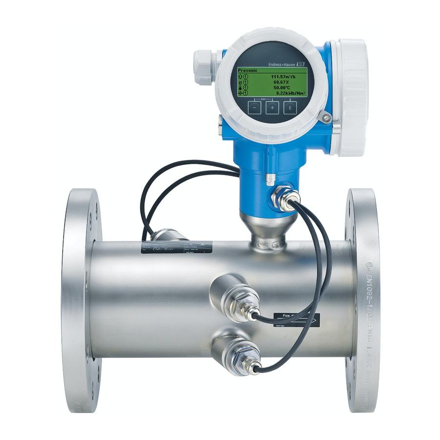
Product description Proline Prosonic Flow B 200 Product description Product design A0016199 1 Important components of a measuring device Electronics compartment cover Display module Main electronics module Cable glands Transmitter housing I/O electronics module Terminals (spring loaded terminals, pluggable) -
Page 9: Incoming Acceptance And Product Identification
(depends on device version) and documents present? • If one of the conditions is not satisfied, contact your Endress+Hauser Sales Center. • Depending on the device version, the CD-ROM might not be part of the delivery! The Technical Documentation is available via the Internet or via the Endress+Hauser Operations App. -
Page 10: Product Identification
• Enter serial numbers from nameplates in W@M Device Viewer (www.endress.com/deviceviewer): All information about the measuring device is displayed. • Enter the serial number from the nameplates into the Endress+Hauser Operations App or scan the 2-D matrix code (QR code) on the nameplate with the Endress+Hauser Operations App: all the information for the measuring device is displayed. -
Page 11: Transporting The Product
Proline Prosonic Flow B 200 Storage and transport Transporting the product WARNING Center of gravity of the measuring device is higher than the suspension points of the webbing slings. Risk of injury if the measuring device slips. ‣ Secure the measuring device from rotating or slipping. - Page 12 Storage and transport Proline Prosonic Flow B 200 A0015605 Endress+Hauser...
-
Page 13: Mounting
Proline Prosonic Flow B 200 Mounting Mounting Installation conditions No special measures such as supports are necessary. External forces are absorbed by the construction of the device. 6.1.1 Mounting position Mounting location A0015543 Orientation The direction of the arrow on the sensor helps you to install the sensor according to the flow direction. - Page 14 Mounting Proline Prosonic Flow B 200 Orientation Compact version Vertical orientation A0015545 Horizontal orientation, transmitter head up * A0015589 Horizontal orientation, transmitter head down * A0015590 Horizontal orientation, transmitter head at side A0015592 * A maximum deviation of only ±3 ° is permitted for the horizontal alignment of the transducers.
- Page 15 Proline Prosonic Flow B 200 Mounting Single-path version: DN 50 (2"), DN 80 (3") 20 × DN 3 × DN 20 × DN 3 × DN 20 × DN 3 × DN 20 × DN 3 × DN A0015453 3 Single-path version: minimum inlet and outlet runs with various flow obstructions 90 °...
- Page 16 Mounting Proline Prosonic Flow B 200 Two-path version: DN 100 to 200 (4 to 8") 10 × DN 3 × DN 10 × DN 3 × DN 10 × DN 3 × DN 10 × DN 3 × DN A0015553 ...
-
Page 17: Mounting The Measuring Device
Proline Prosonic Flow B 200 Mounting nor applied to the sensor. Thermal insulation can ensure that such heat transfer does not take place. Thermal insulation is particularly recommended in situations where there is a large difference between the process temperature and the ambient temperature. This can result in heat convection errors during temperature measurement. -
Page 18: Post-Mounting Check
Mounting Proline Prosonic Flow B 200 6.2.4 Turning the transmitter housing To provide easier access to the connection compartment or display module, the transmitter housing can be turned: max. 350° 8 mm 8 mm A0013713 6.2.5 Turning the display module... - Page 19 Proline Prosonic Flow B 200 Mounting Has the correct orientation for the sensor been selected (→ 13)? • According to sensor type • According to medium temperature • According to medium properties (outgassing, with entrained solids) Does the arrow on the sensor match the direction of flow of the medium through the piping (→ 13)? ...
-
Page 20: Electrical Connection
Electrical connection Proline Prosonic Flow B 200 Electrical connection Connection conditions 7.1.1 Required tools • For cable entries: Use corresponding tools • For securing clamp: Allen key 3 mm • Wire stripper • When using stranded cables: Crimping tool for wire end ferrule •... - Page 21 Proline Prosonic Flow B 200 Electrical connection Transmitter A0018179 4-20 mA HART connection version with additional outputs, without integrated overvoltage protection 1.1 Output 1 (passive): 4-20 mA HART 1.2 Output 2 (passive): no assignment, pulse/frequency/switch output or 4-20 mA 1.3 Ground terminal for cable shield 4-20 mA HART connection version with additional outputs, with integrated overvoltage protection 2.1 Output 1 (passive): 4-20 mA HART...
- Page 22 Electrical connection Proline Prosonic Flow B 200 Calculation of the maximum load Depending on the supply voltage of the power supply unit (U ), the maximum load (R including line resistance must be observed to ensure adequate terminal voltage at the device.
-
Page 23: Connecting The Measuring Device
Proline Prosonic Flow B 200 Electrical connection Connecting the measuring device NOTICE Limitation of electrical safety due to incorrect connection! ‣ For use in potentially explosive atmospheres, observe the information in the device-specific Ex documentation. 7.2.1 Connecting the transmitter Connection via terminals... -
Page 24: Ensuring The Degree Of Protection
Electrical connection Proline Prosonic Flow B 200 Removing a cable 3 (0.12) mm (in) A0013835 Ensuring the degree of protection The measuring device fulfills all the requirements for the IP66/67 degree of protection, Type 4X enclosure. To guarantee IP66/67 degree of protection, Type 4X enclosure, carry out the following steps after the electrical connection: Check that the housing seals are clean and fitted correctly. -
Page 25: Post-Connection Check
Proline Prosonic Flow B 200 Operation options Post-connection check Are cables or the device undamaged (visual inspection)? Do the cables comply with the requirements (→ 20)? Do the cables have adequate strain relief? Are all the cable glands installed, firmly tightened and leak-tight? Cable run with "water trap"... - Page 26 Operation options Proline Prosonic Flow B 200 8.1.2 Operating philosophy The individual parts of the operating menu are assigned to certain user roles. Each user role corresponds to typical tasks within the device lifecycle. For detailed information about the operating philosophy of the instrument, refer to the...
-
Page 27: Access To The Operating Menu Via The Local Display
Proline Prosonic Flow B 200 Operation options Access to the operating menu via the local display X X X X X X 19.184 mA 12.5 X X X X X X Language à 20.50 English Deutsch Español Français User ABC_... - Page 28 Operation options Proline Prosonic Flow B 200 8.2.1 Operational display Status area Status signals A0013956 A0013959 A0013958 A0013957 Failure Function check Out of specification Maintenance required Diagnostic behavior Locking Communication A0013961 A0013962 A0013965 A0013963 Alarm Warning Device locked Remote operation enabled...
- Page 29 Proline Prosonic Flow B 200 Operation options Symbols for diagnostic behavior The diagnostic behavior pertains to a diagnostic event that is relevant to the displayed measured variable. For more information about the symbols, refer to the "Status area" section (→ 28) 8.2.2...
- Page 30 Operation options Proline Prosonic Flow B 200 Operating symbols in the text editor A0014040 A0013981 Clears all entered characters. Toggle • Between upper-case and lower-case letters • For entering numbers • For entering special characters Correction symbols under A0013990 A0013991...
- Page 31 Proline Prosonic Flow B 200 Operation options Meaning Enter key For operational display • Pressing the key briefly opens the operating menu. • Pressing the key for 2 s opens the context menu. In a menu, submenu • Pressing the key briefly: –...
- Page 32 Operation options Proline Prosonic Flow B 200 Press for 2 s. The help text for the selected parameter opens. Press + simultaneously. The help text is closed. 8.2.6 User roles and related access authorization The two user roles "Operator" and "Maintenance" have different write access to the parameters if the customer defines a user-specific access code.
-
Page 33: Access To The Operating Menu Via The Operating Tool
Proline Prosonic Flow B 200 Operation options The keypad lock is enabled and disabled in the same way: The user is in the operational display. ‣ By simultaneously pressing the + + keys. After enabling the keypad lock:... - Page 34 Operation options Proline Prosonic Flow B 200 8.3.1 Via HART protocol A0013764 5 Options for remote operation via HART protocol Control system (e.g. PLC) Transmitter power supply unit, e.g. RN221N (with communication resistor) Connection for Commubox FXA195 and Field Communicator 475 Field Communicator 475 Computer with operating tool (e.g.
-
Page 35: Commissioning
Proline Prosonic Flow B 200 Commissioning 8.3.2 Via service interface (CDI) A0014019 Service interface (CDI = Endress+Hauser Common Data Interface) of the measuring device Commubox FXA291 Computer with "FieldCare" operating tool with COM DTM "CDI Communication FXA291" Commissioning Function check Before commissioning the device, make sure that the post-installation and post-connection checks have been performed. -
Page 36: Setting The Operating Language
Commissioning Proline Prosonic Flow B 200 Setting the operating language Factory setting: English or ordered local language X X X X X X X 20.50 Main menu 0104-1 Language English Display/operat. Setup Language 0104-1 English à Deutsch Español Français Language 0104-1 Ã... -
Page 37: Defining The Tag Name
Proline Prosonic Flow B 200 Commissioning Defining the tag name To enable quick identification of the measuring point within the system, you can enter a unique designation using the Device tag parameter and thus change the factory setting. Navigation path Setup →... - Page 38 Commissioning Proline Prosonic Flow B 200 The device automatically locks the write-protected parameters again if a key is not pressed for 10 minutes in the navigation and editing view. The device locks the write-protected parameters automatically after 60 s if the user skips back to the operational display mode from the navigation and editing view.
-
Page 39: Diagnostic Information
Proline Prosonic Flow B 200 Diagnostic information Display module is attached to the edge of the electronics compartment. Setting the write protection switch (WP) on the main electronics module to the ON position enables the hardware write protection. The Hardware locked option is displayed in the Locking status parameter. In addition, on the local display the -symbol appears in front of the parameters in the header of the operational display and in the navigation view. - Page 40 Diagnostic information Proline Prosonic Flow B 200 X X X X X X X X X X X X X X 20.50 S801 Supply voltage Menu Diagnostic list Diagnostics 1 S801 Supply voltage Diagnostics 2 Diagnostics 3 Supply voltage (ID:203)
- Page 44 www.addresses.endress.com...
Need help?
Do you have a question about the Proline Prosonic Flow B 200 and is the answer not in the manual?
Questions and answers