Endress+Hauser PROline prosonic flow 90 Operating Instructions Manual
Ultrasonic flow measuring system
Hide thumbs
Also See for PROline prosonic flow 90:
- Installation instruction (16 pages) ,
- Installation instruction (8 pages) ,
- Operating instructions manual (114 pages)

Subscribe to Our Youtube Channel
Related Manuals for Endress+Hauser PROline prosonic flow 90


Summary of Contents for Endress+Hauser PROline prosonic flow 90
- Page 1 PROline prosonic flow 90 BA 068D/06/en/12.02 50099981 Ultrasonic Flow Measuring valid from software version: V 1.05.XX (measuring amplifier) V 1.02.XX (communication) System Operating Instructions...
- Page 2 Brief operating instructions PROline Prosonic Flow 90 Brief operating instructions These brief operating instructions explain how to configure your measuring device quickly and easily: Safety instructions Page 7 Please read the safety instructions through carefully. Connecting the transmitter Page 35 Install the sensors using the transmitter software.
- Page 3 PROline Prosonic Flow 90 Brief operating instructions “SENSOR INSTALLATION” Quick Setup Page 60 Use this “Quick Setup” to determine the data required for sensor installation such as sensor spacing (1), cord length, pipe materials, sound velocity in fluids, etc. – The system provides you with the sensor distance for the W/P/U "Clamp On"...
- Page 4 Brief operating instructions PROline Prosonic Flow 90 Endress+Hauser...
-
Page 5: Table Of Contents
PROline Prosonic Flow 90 Table of Contents Table of Contents Safety instructions ....7 Connecting the measuring unit ... . 35 4.2.1... - Page 6 Table of Contents PROline Prosonic Flow 90 Technical data ....91 10.1 Technical data at a glance ....91 10.1.1...
-
Page 7: Safety Instructions
The device must be operated by persons authorized and trained by the plant opera- tor. Strict compliance with the instructions in the Operating Instructions is mandatory. x Endress+Hauser will be happy to assist in clarifying the chemical resistance proper- ties of parts wetted by special fluids, including fluids used for cleaning. -
Page 8: Return
Endress+Hauser: x Always, enclose a fully completed “Declaration of contamination” form. Only then can Endress+Hauser transport, examine and repair a returned device. x Enclose special handling instructions if necessary, for example a safety data sheet as per EN 91/155/EEC. -
Page 9: Identification
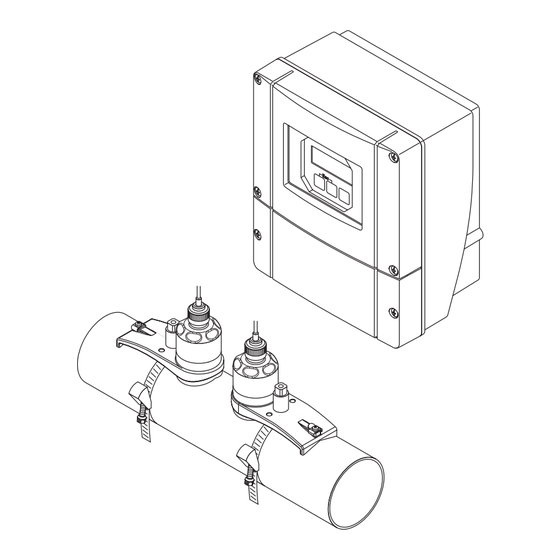
PROline Prosonic Flow 90 2 Identification Identification Device designation The "Prosonic Flow 90" flowmeter system consists of the following components: x Transmitter Prosonic Flow 90 x Measuring sensors Prosonic Flow W and U 2.1.1 Nameplate of the transmitter ENDRESS+HAUSER PROSONIC FLOW 90... -
Page 10: Nameplate Of The Prosonic Flow W Sensors
2 Identification PROline Prosonic Flow 90 2.1.2 Nameplate of the Prosonic Flow W sensors ENDRESS+HAUSER PROSONIC FLOW W XXXXX-XXXXXXXXXXXX Order Code: XA0..D/ 12345678901 RY 2001 Ser.No.: 06/a3/..W-CL-1F-L-B Type: DN100 - DN4000 -20°C (-4°F) ... +80°C (+175°F) OPEN CLOSE IP67... -
Page 11: Ce Mark, Declaration Of Conformity
Laboratory Procedures” and with the EMC requirements of EN 61326/A1. The measuring system described in these Operating Instructions is therefore in con- formity with the statutory requirements of the EC Directives. Endress+Hauser confirms succesful testing of the device by affixing to it the CE mark. - Page 12 2 Identification PROline Prosonic Flow 90 Endress+Hauser...
-
Page 13: Installation
PROline Prosonic Flow 90 3 Installation Installation Incoming acceptance, transport and storage 3.1.1 Incoming acceptance x Check the packaging and the contents for damage. x Check the shipment, make sure nothing is missing and that the scope of supply matches your order. -
Page 14: Installation Conditions
3 Installation PROline Prosonic Flow 90 Installation conditions 3.2.1 Installation dimensions The dimensions and the fitting lengths of the sensors and the transmitter are on Page 97 ff. 3.2.2 Installation location Correct measuring is possible only if the pipe is full. Avoid the following installation loca- tions: x Do not install at the highest point in the run. -
Page 15: Orientation
PROline Prosonic Flow 90 3 Installation 3.2.3 Orientation Vertical orientation Recommended orientation with upward direction of flow (View A). Entrained solids sink down. Gases rise away from the measuring sensor when fluid is not flowing. The piping can be completely drained and protected against build-up. -
Page 16: Inlet And Outlet Runs (Insertion Version)
3 Installation PROline Prosonic Flow 90 3.2.5 Inlet and outlet runs (Insertion version) If possible, install the sensor well clear of assemblies such as valves, T-pieces, elbows, etc. The longest inlet or outlet run must always be taken into account if several flow obstructions are built in. -
Page 17: Installation Instructions
PROline Prosonic Flow 90 3 Installation Installation instructions 3.3.1 Installing tensioning bands (Clamp On) For W sensors DN 50...200 Push one of the supplied threaded bolts on the tensioning band. Run the tensioning band around the pipe without twisting it and push the end through the tensioning band lock (make sure that the screw is pushed up). - Page 18 3 Installation PROline Prosonic Flow 90 Fig. 10: Tensioning band installation for DN 250...4000 For U sensors - DN 15...100 The procedure for installing the tensioning bands for the U sensor is explained on Page 23 in the "Installing the sensor Prosonic Flow U" Section.
-
Page 19: Use Of Weld Bolts For W Sensors
PROline Prosonic Flow 90 3 Installation 3.3.2 Use of weld bolts for W sensors Weld bolts can be used instead of tensioning bands for the following types of installation of the W Clamp On measuring sensors. To determine the sensor spacing, (distance from the center of the first bolt to the center of the second bolt), use the Quick Setup program “Sensor Installation”... -
Page 20: Installing The Prosonic Flow W Measuring Sensors (Clamp On)
3 Installation PROline Prosonic Flow 90 3.3.3 Installing the Prosonic Flow W measuring sensors (Clamp On) 1 or 3 traverses version Fix a tensioning band for small or large nominal diameters as described on Page 17. Install the second tensioning band (threaded bolt on the opposite side). The sec- ond tensioning band must still be moveable. - Page 21 PROline Prosonic Flow 90 3 Installation Push both of the sensor holders onto the pipe over the threaded bolts and tighten the locking nuts using a spanner (AF 13). Fig. 14: Installing the sensor holders Coat the contact surface of the sensors with an even (approx. 1 mm thick) layer of the coupling fluid (from the center to the groove, see Page 67).
- Page 22 3 Installation PROline Prosonic Flow 90 3.3.4 Installing the Prosonic Flow W measuring sensors (Clamp On) 2 or 4 traverses version Fix a tensioning band for small or large nominal diameters as described on Page 17. Do not fasten the second tensioning band. You must still be able to move the sec- ond tensioning band along the pipe.
-
Page 23: Installing The Prosonic Flow U Measuring Sensors (Clamp On)
PROline Prosonic Flow 90 3 Installation 3.3.5 Installing the Prosonic Flow U measuring sensors (Clamp On) In the case of pipes in the DN 15…32 nominal diameter range, use the retaining vee (a) supplied to reinforce the pipe. This retaining vee is only included in the DN 15….40 installation set (see Accessories on Page 69). - Page 24 3 Installation PROline Prosonic Flow 90 Set the sensor distance on the sensor assembly by moving the sensors (c) along the assembly frame and tightening the sensor fixing nuts (d). Preferably, the sensor position is set symmetrically to the rail centre.
- Page 25 PROline Prosonic Flow 90 3 Installation Push down the screws (h) of tensioning band lock and tighten with a screwdriver so the bands cannot slip. If so desired, shorten the tensioning band then to the desired length. " Caution! x Danger of injury! Avoid sharp edges when shortening the tensioning band.
-
Page 26: Term Explanations For Prosonic Flow W (Insertion Version)
3 Installation PROline Prosonic Flow 90 3.3.6 Term explanations for Prosonic Flow W (Insertion version) The graphic below provides you with an overview of the terms used when installing Prosonic Flow W (Insertion version). Fig. 23: Explanation of terms for single path version... -
Page 27: Installing The Measuring Sensors Prosonic Flow W (Single Path Insertion Version)
PROline Prosonic Flow 90 3 Installation 3.3.7 Installing the measuring sensors Prosonic Flow W (single path Insertion version) Determine the installation area (e) on the pipe section: – Installation location: Page 14 – Inlet/outlet runs: Page 16 – Space required by the measuring point approx. 1x pipe diameter. - Page 28 3 Installation PROline Prosonic Flow 90 Mark the sensor distance (a) from the middle line starting from the first drillhole. Project the middle line to the back of the pipe and draw it on. Fig. 26: Installing the measuring sensors, steps 5 and 6 Mark the drillhole on the middle line on the back of the pipe.
- Page 29 PROline Prosonic Flow 90 3 Installation 10. Weld in both sensor holders. After welding, check the distance between the drill holes once again and measure the path length. Note! The path length is given as a measurement in the Quick Setup menu (function “PATH LENGTH”).
-
Page 30: Installing The Wall-Mount Housing
3 Installation PROline Prosonic Flow 90 3.3.8 Installing the wall-mount housing There are various ways of installing the wall-mount transmitter housing: x Direct wall mounting x Panel mounting (with separate mounting kit, accessories o Page 69) x Pipe mounting (with separate mounting kit, accessories o Page 69) "... - Page 31 PROline Prosonic Flow 90 3 Installation Panel mounting Prepare the installation opening in the panel (Fig. 31). Slide the housing through the front of the panel cutout. Screw the fasteners to the wall-mount housing. Screw the threaded rods into the brackets and tighten until the housing is firmly fixed to the panel wall.
-
Page 32: Installation Check
3 Installation PROline Prosonic Flow 90 Installation check Perform the following checks after installing the measuring device on the pipe: Device condition and specifications Notes Is the device damaged (visual inspection)? Does the device correspond to specifications at the measuring point, see Page 89 ff. -
Page 33: Wiring
PROline Prosonic Flow 90 4 Wiring Wiring Warning! When connecting Ex-certified devices, see the notes and diagrams in the Ex-specific supplement to these Operating Instructions. Please do not hesitate to contact your E+H sales office if you have any questions. -
Page 34: Cable Specifications
4 Wiring PROline Prosonic Flow 90 Legend: View A Detail B Connection compartment cover Sensor cable plug, upstream Sensor cable plug, downstream Cable entry (not required) Cable entry (not required) Cable gland cover Rubber seal Cable gland holder Cable fixing sleeves... -
Page 35: Connecting The Measuring Unit
PROline Prosonic Flow 90 4 Wiring Connecting the measuring unit 4.2.1 Connecting the transmitter Warning! x Risk of electric shock. Switch off the power supply before opening the device. Do not install or wire the device while it is connected to the power supply. Failure to comply with this precaution can result in irreparable damage to the electronics. -
Page 36: Terminal Assignment
4 Wiring PROline Prosonic Flow 90 4.2.2 Terminal assignment Terminal No. (inputs/outputs) Order variant 20 (+) / 21 (–) 22 (+) / 23 (–) 24 (+) / 25 (–) 26 (+) / 27 (–) Current output 90***-***********W HART Current output... -
Page 37: Hart Connection
PROline Prosonic Flow 90 4 Wiring 4.2.3 HART connection Users have the following connection options at their disposal: x Direct connection to transmitter by means of terminals 26 / 27 x Connection by means of the 4...20 mA circuit. Note! x The measuring loop's minimum load must be at least 250 : . -
Page 38: Potential Equalisation
4 Wiring PROline Prosonic Flow 90 Potential equalisation For potential equalisation no special measures are necessary. Note! For instruments for use in hazardous areas, observe the corresponding guidelines in the specific Ex documentation. Degree of protection Transmitter (wallmount housing) The transmitter fulfills all the requirements for IP 67 degree of protection. Compliance... -
Page 39: Connection Check
PROline Prosonic Flow 90 4 Wiring Flowrate measuring sensors U (Clamp on) The flowrate measuring sensors U fulfill all the requirements for IP 52 degree of protec- tion. Compliance with the following points is mandatory following installation in the field or servicing, in order to ensure that IP 52 protection is maintained: x Only use cables supplied by E+H with the corresponding sensor connectors. - Page 40 4 Wiring PROline Prosonic Flow 90 Endress+Hauser...
-
Page 41: Operation
PROline Prosonic Flow 90 5 Operation Operation Display and operating elements The local display enables you to read all important parameters directly at the measuring point and configure the device using the “Quick Setup” or the function matrix. The display consists of two lines; this is where measured values and/or status variables (direction of flow, bar graph, etc.) are displayed. -
Page 42: Brief Operating Instructions For The Function Matrix
5 Operation PROline Prosonic Flow 90 Brief operating instructions for the function matrix Note! x Please refer to the general notes on Page 43. x Function descriptions o see the “Description of Device Functions” manual HOME position o F o Entry to the function matrix Select a function group (e.g. -
Page 43: General Notes
There is no need to change these parameters under normal circumstances and conse- quently, they are protected by a special code known only to the E+H service organisa- tion. Please contact Endress+Hauser if you have any questions. 5.2.3 Disabling the programming mode Programming mode is disabled if you do not press an operating element within 60 sec- onds after you return to the HOME position. -
Page 44: Error Messages
5 Operation PROline Prosonic Flow 90 Error messages Type of error Errors that occur during commissioning or measuring operation are displayed immedi- ately. If two or more system or process errors occur, the error with the highest priority is always the one shown on the display. -
Page 45: Communication (Hart)
PROline Prosonic Flow 90 5 Operation Communication (HART) In addition to local operation, the measuring device can also be configured and meas- ured values obtained by means of the HART protocol. Digital communication takes place using the 4...20 mA current output HART (see Page 37). -
Page 46: Device Variables And Process Variables
5 Operation PROline Prosonic Flow 90 Further operating programs x “AMS” operating program (Fisher Rosemount) x “SIMATIC PDM” operating program (Siemens) Note! The HART protocol requires the “4...20mA HART” or “4...20 mA (25 mA) HART” setting in the CURRENT RANGE function (current output 1). -
Page 47: Universal / Common Practice Hart Commands
PROline Prosonic Flow 90 5 Operation 5.4.3 Universal / common practice HART commands The following table contains all the universal and common practice commands sup- ported by Prosonic Flow 90. Command No. Command data Response data HART command / Access type... - Page 48 5 Operation PROline Prosonic Flow 90 Command No. Command data Response data HART command / Access type (numeric data in decimal form) (numeric data in decimal form) Read the primary process none 24 bytes are sent as a response: –...
- Page 49 PROline Prosonic Flow 90 5 Operation Command No. Command data Response data HART command / Access type (numeric data in decimal form) (numeric data in decimal form) – Read TAG, TAG descriptor none – Byte 0 5: TAG name –...
- Page 50 5 Operation PROline Prosonic Flow 90 Command No. Command data Response data HART command / Access type (numeric data in decimal form) (numeric data in decimal form) Common Practice Commands – Write damping value for pri- Byte 0 3: Damping value of the primary proc-...
- Page 51 PROline Prosonic Flow 90 5 Operation Command No. Command data Response data HART command / Access type (numeric data in decimal form) (numeric data in decimal form) Write unit of primary process Set unit of primary process variable Only unit...
- Page 52 5 Operation PROline Prosonic Flow 90 Command No. Command data Response data HART command / Access type (numeric data in decimal form) (numeric data in decimal form) Write assignments of the Setting of the device variables to the four proc-...
-
Page 53: Device Status / Error Messages
PROline Prosonic Flow 90 5 Operation 5.4.4 Device status / Error messages You can read the extended device status, in this case, current error messages, via Com- mand “48”. The command delivers information which are partly coded in bits (see table below). - Page 54 5 Operation PROline Prosonic Flow 90 Byte Error no. Short error description ( Page 74 ff. ) not assigned – not assigned – not assigned – not assigned – not assigned – not assigned – not assigned – not assigned –...
- Page 55 PROline Prosonic Flow 90 5 Operation Byte Error no. Short error description ( Page 74 ff. ) not assigned – not assigned – not assigned – not assigned – not assigned – not assigned – not assigned – not assigned –...
- Page 56 5 Operation PROline Prosonic Flow 90 Byte Error no. Short error description ( Page 74 ff. ) not assigned – Initialization is running. All outputs set to “0”. not assigned – Positive zero return active not assigned – not assigned –...
- Page 57 PROline Prosonic Flow 90 5 Operation Byte Error no. Short error description ( Page 74 ff. ) not assigned – not assigned – not assigned – not assigned – not assigned – not assigned – not assigned – not assigned –...
- Page 58 5 Operation PROline Prosonic Flow 90 Endress+Hauser...
-
Page 59: Commissioning
PROline Prosonic Flow 90 6 Commissioning Commissioning Function check Make sure that all final checks have been completed before you start up your measuring point: x “Installation check” checklist o Page 32 x “Connection check” checklist o Page 39 Commissioning 6.2.1... -
Page 60: Sensor Installation" Quick Setup Menu
6 Commissioning PROline Prosonic Flow 90 6.2.2 “Sensor installation” Quick Setup menu Use this “Quick Setup” to determine the sensor spacing required for sensor installation. ENDRESS+HAUSER Setup Quick Setup Sensor HOME-POSITION Language QS-Sensor ➀ Units Measurement Selection Clamp On Insertion... -
Page 61: Commissioning" Quick Setup Menu
PROline Prosonic Flow 90 6 Commissioning 6.2.3 “Commissioning” Quick Setup menu This Quick Setup menu guides you systematically through the setup procedure for all the major device functions that have to be configured for standard measuring operation. ENDRESS+HAUSER Quick Setup Commission. - Page 62 6 Commissioning PROline Prosonic Flow 90 Note! The display returns to the function cell QUICK SETUP COMMISSIONING if you press the ESC key ( ) during interrogation. ➀ Only the units not yet configured in the current Quick Setup are offered for selection in each cycle.
-
Page 63: Zero Point Adjustment
PROline Prosonic Flow 90 6 Commissioning 6.2.4 Zero point adjustment Consequently, zero point adjustment is generally not necessary. Experience shows that the zero point adjustment is advisable only in special cases: x To achieve highest measuring accuracy also with very small flow rates. - Page 64 6 Commissioning PROline Prosonic Flow 90 Performing a zero point adjustment Operate the system until normal operating conditions resume. Stop the flow (v = 0 m/s). Check the shut-off valves for leaks. Check that operating pressure is correct. Using the local display, select the “ZERO POINT ADJUSTMENT” function in the...
-
Page 65: Current Output: Active/Passive
PROline Prosonic Flow 90 6 Commissioning 6.2.5 Current output: active/passive The current output can be configured as “active” or “passive” by means of various jump- ers on the I/O board. Warning! Risk of electric shock. Exposed components carry dangerous voltages. Make sure that the power supply is switched off before you remove the cover of the electronics com- partment. - Page 66 6 Commissioning PROline Prosonic Flow 90 Endress+Hauser...
-
Page 67: Maintenance
PROline Prosonic Flow 90 7 Maintenance Maintenance The Prosonic Flow 90 flow measuring system requires no special maintenance. Exterior cleaning When cleaning the exterior of measuring devices, always use cleaning agents that do not attack the surface of the housing and the seals. - Page 68 7 Maintenance PROline Prosonic Flow 90 Endress+Hauser...
-
Page 69: Accessories
PROline Prosonic Flow 90 8 Accessories Accessories Various accessories, which can be ordered separately from Endress+Hauser, are avail- able for the transmitter and the sensor. The E+H service organisation can provide detailed information on the order codes of your choice. - Page 70 8 Accessories PROline Prosonic Flow 90 Accessory Description Order Code – Sensor cable set for 5 m sensor cable, PVC, 20...+70 °C DK9SC – Prosonic Flow W sensors 10 m sensor cable, PVC, 20...+70 °C DK9SC – 15 m sensor cable, PVC, 20...+70 °C...
- Page 71 PROline Prosonic Flow 90 8 Accessories Accessory Description Order Code FieldCheck Tester/simulator for testing flowmeters in the DXC10 field. When used in conjunction with the “FieldTool” software package, test results can be imported into a database, printed and used for official cer- tification.
- Page 72 8 Accessories PROline Prosonic Flow 90 Endress+Hauser...
-
Page 73: Trouble-Shooting
PROline Prosonic Flow 90 9 Trouble-shooting Trouble-shooting Trouble-shooting instructions Always start trouble-shooting with the checklist below, if faults occur after start-up or during operation. This takes you directly (via various queries) to the cause of the prob- lem and the appropriate remedial measures. -
Page 74: System Error Messages
9 Trouble-shooting PROline Prosonic Flow 90 System error messages Serious system errors are always recognized by the instrument as “Fault message”, and are shown as a lightning flash ($) on the display. Fault messages immediately affect the inputs and outputs. Simulations and measured-value suppression, on the other hand, are classed and displayed as information messages. - Page 75 PROline Prosonic Flow 90 9 Trouble-shooting Type Error message / No. Cause Remedy / spare part SENSOR DOWN Connection between sensor and – Check the cable connection # 081 transmitter interrupted between the sensor and the transmitter. – Check that the sensor connec- tor is fully screwed in.
- Page 76 9 Trouble-shooting PROline Prosonic Flow 90 Type Error message / No. Cause Remedy / spare part STACK PULSE n The temporarily buffered flow por- 1. Increase the setting for pulse # 347...350 tions (measuring mode for pulsat- weighting ing flow) could not be cleared or 2.
- Page 77 PROline Prosonic Flow 90 9 Trouble-shooting Type Error message / No. Cause Remedy / spare part SIGNAL TOO LOW Attenuation of acoustic measure- – Check to see if the coupling # 391 ment section too high. fluid must be renewed.
-
Page 78: Process Error Messages
9 Trouble-shooting PROline Prosonic Flow 90 Process error messages Process errors can be defined as either “Fault” or “Notice” messages and can thereby be weighted differently. Determination of this is done via the function matrix ( o see the “Description of Device Functions” manual). -
Page 79: Process Errors Without Messages
Returning devices to E+H The procedures on Page 8 must be carried out before you return a flowm- eter requiring repair or calibration to Endress+Hauser. In all cases, enclose a fully completed “Declaration of contamination” form with the flowmeter. You will find a preprinted form at the end of these Operating Instructions. -
Page 80: Response Of Outputs To Errors
9 Trouble-shooting PROline Prosonic Flow 90 Response of outputs to errors Note! The failsafe mode of totalizers, current, pulse and frequency outputs can be customized by means of various functions in the function matrix. You will find detailed information on these procedures in the “Description of Device Functions”... - Page 81 PROline Prosonic Flow 90 9 Trouble-shooting Failsafe mode of outputs and totalizers Process/system error is present Positive zero return is activated Frequency output FALLBACK VALUE Output signal corresponds to Signal output 0 Hz “zero flow” FAILSAFE LEVEL Output of the frequency specified in the FAIL- SAFE VALUE function.
-
Page 82: Spare Parts
9 Trouble-shooting PROline Prosonic Flow 90 Spare parts Chap. 9.1 contains a detailed trouble-shooting guide. The measuring device, more over, provides additional support in the form of continuous self-diagnosis and error mes- sages. Trouble-shooting can entail replacing defective components with tested spare parts. -
Page 83: Removing And Installing Printed Circuit Boards
Remove the cover (4) from the electronics compartment by loosening the screws. Removal of boards (6, 7, 8): Insert a thin pin into the opening (5) and pull the board out of the holder. Installation is the reverse of the removal procedure. " Caution! Use only original Endress+Hauser replacement parts. Endress+Hauser... - Page 84 9 Trouble-shooting PROline Prosonic Flow 90 Fig. 50: Wall-mount housing: removing and installing printed circuit boards Housing cover Electronics module Ribbon cable (display module) Screws of electronics compartment cover Aperture for installing/removing boards Power unit board Amplifier board Sensor signal cable...
-
Page 85: Installation/Removal Of Flowmeter Sensors W "Insertion
PROline Prosonic Flow 90 9 Trouble-shooting Installation/removal of flowmeter sensors W “Insertion” The active part of the flowmeter sensor W “Insertion” can be replaced without interrupt- ing the process. Pull the sensor connector (1) out of the sensor cover (3). -
Page 86: Replacing The Device Fuse
– Power supply 85...260 V AC o 0.8 A slow-blow; 5.2 x 20 mm – Ex-systems o see appropriate Ex documentation Assembly is the reverse of the disassembly procedure. " Caution! Use only original Endress+Hauser replacement parts. Fig. 52: Replacing the device fuse on the power unit board Protective cap Device fuse... -
Page 87: Software History
PROline Prosonic Flow 90 9 Trouble-shooting 9.10 Software history Software version / Changes to software Documentation date Changes/Additions Amplifier V 1.00.00 / 06.2001 Original software. Compatible with: – FieldTool – HART communicator DXR 275 (OS 4.6 and higher) with rev. 1, DD 1. - Page 88 9 Trouble-shooting PROline Prosonic Flow 90 Endress+Hauser...
-
Page 89: Technical Data
PROline Prosonic Flow 90 10 Technical data Technical data 10.1 Technical data at a glance 10.1.1 Application x Measuring the flow rate of fluids in closed piping systems. x Applications in measuring, control and regulation technology for monitoring processes. 10.1.2... -
Page 90: Output
10 Technical data PROline Prosonic Flow 90 10.1.4 Output Output signal Current output: Active/passive selectable, galvanically isolated, time constant selectable (0.05...100 s), full scale value selectable, temperature coefficient: typically 0.005% o.r./°C, resolution: 0.5 µA. x active: 0/4...20 mA, R < 700 : (for HART: R t 250 : ) x passive: 4...20 mA, max. -
Page 91: Power Supply
PROline Prosonic Flow 90 10 Technical data 10.1.5 Power supply Electrical connections see Page 33 ff. Potential equalisation see Page 38 Cable entries Power supply and signal cables (inputs/outputs): x Cable entry M20 x 1.5 or x Cable gland for cables with Ø 6...12 mm x Threaded adapter 1/2"... -
Page 92: Performance Characteristics
10 Technical data PROline Prosonic Flow 90 10.1.6 Performance characteristics x Fluid temperature: +28 °C ± 2 K Reference operating x Ambient temperature: +22 °C ± 2 K conditions x Warm-up period: 30 minutes Installation: x Inlet run >10 x DN x Outlet run >... -
Page 93: Operating Conditions
PROline Prosonic Flow 90 10 Technical data 10.1.7 Operating conditions Installation Installation instructions Any orientation (vertical, horizontal) Restrictions and additional installation instructions o Page 14 ff. Clamp On version o Page 15 Inlet and outlet runs Insertion version o Page 16... - Page 94 10 Technical data PROline Prosonic Flow 90 Shock and vibration according to IEC 68-2-6 resistance Electromagnetic compati- To EN 61326/A1 (IEC 1326) “Emmision to class A requirements” and NAMUR Recom- bility (EMC) mendations NE 21. Process conditions x Flowrate measuring sensors Prosonic Flow W (Clamp On):...
-
Page 95: Mechanical Construction
PROline Prosonic Flow 90 10 Technical data 10.1.8 Mechanical construction Design / dimensions see Page 97 ff. Weight Transmitter housing: x Wall-mount housing: 6.0 kg Measuring sensors: x Flowrate measuring sensors W (Clamp On) incl. mounting rail and tensioning bands: 2.8 kg... -
Page 96: 10.1.10 Certificates And Approvals
(hazardous Zone 2). CE mark The measuring system is in conformity with the statutory requirements of the EC Directives. Endress+Hauser confirms successful testing of the device by affixing to it the CE mark. Other standards and EN 60529: guidelines Degrees of protection by housing (IP code) -
Page 97: Dimensions Of Wall-Mount Housing
PROline Prosonic Flow 90 10 Technical data 10.2 Dimensions of wall-mount housing Fig. 54: Dimensions of wall-mount housing (panel mounting and pipe installation Page 31) Endress+Hauser... -
Page 98: Dimensions Of W Sensors (Clamp On)
10 Technical data PROline Prosonic Flow 90 10.3 Dimensions of W sensors (Clamp On) Fig. 55: Dimensions of W sensor (Clamp On) a = Sensor spacing can be determined using Quick Setup b = Pipe outer diameter (defined by the application) 10.4... -
Page 99: Dimensions Of W Sensors (Insertion Version)
PROline Prosonic Flow 90 10 Technical data 10.5 Dimensions of W sensors (Insertion version) ~ 150 Fig. 57: Dimensions of W sensors (Insertion version) A = View A a = Pipe outer diameter (defined by the application) b = Sensor spacing determinable using Quick Setup... - Page 100 10 Technical data PROline Prosonic Flow 90 Endress+Hauser...
-
Page 101: Index
PROline Prosonic Flow 90 Index Index Accessories ....... 69 Electrical connection Ambient temperature . - Page 102 Index PROline Prosonic Flow 90 Incoming acceptance ..... . . 13 Nameplate Inlet/outlet runs Prosonic Flow 90 transmitter ....9 Clamp On version .
- Page 103 PROline Prosonic Flow 90 Index Safety icons ....... . 8 Zero point adjustment .
- Page 104 Index PROline Prosonic Flow 90 Endress+Hauser...
- Page 105 Declaration of contamination Dear customer, Because of legal determinations and for the safety of our employes and operating equipment we need this “Declaration of contamination” with your signature before your order can be handled. Please put the completely filled in declaration to the instrument and to the shipping documents in any case. Add also safety sheets and/or specific handling instructions if necessary.
- Page 106 Mexico – México, D.F Croatia – Zagreb Tel. (3) 94 40 80, Fax (9) 54 80 38 ❑ Endress+Hauser (México), S.A. de C.V. ❑ Endress+Hauser GmbH+Co. Sweden – Sollentuna Tel. (5) 5 55 68 24 07, Fax (5) 5 55 68 74 59 Malaysia –...
Need help?
Do you have a question about the PROline prosonic flow 90 and is the answer not in the manual?
Questions and answers