Table of Contents
Advertisement
Quick Links
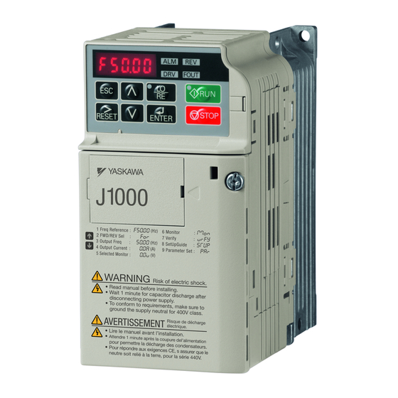
YASKAWA AC Drive-J1000
Compact V/f Control Drive
Quick Start Guide
Type: CIMR-JU
Models: 200 V Class, Three-Phase Input: 0.1 to 5.5 kW
200 V Class, Single-Phase Input: 0.1 to 2.2 kW
400 V Class, Three-Phase Input: 0.2 to 5.5 kW
To properly use the product, read this manual thoroughly and retain
for easy reference, inspection, and maintenance. Ensure the end user
receives this manual.
Contém manual suplementar em Português.
MANUAL NO. TOEP C710606 26B
http://nicontrols.com
Receiving
Mechanical Installation
Electrical Installation
Start-Up Programming &
Operation
Troubleshooting
Periodic Inspection &
Maintenance
Peripheral Devices &
Options
Specifications
Parameter List
Standards Compliance
1
2
3
4
5
6
7
A
B
C
Advertisement
Table of Contents
Troubleshooting

Related Manuals for YASKAWA CIMR-JC4A0002BAA


Summary of Contents for YASKAWA CIMR-JC4A0002BAA
- Page 1 YASKAWA AC Drive-J1000 Compact V/f Control Drive Quick Start Guide Type: CIMR-JU Models: 200 V Class, Three-Phase Input: 0.1 to 5.5 kW 200 V Class, Single-Phase Input: 0.1 to 2.2 kW 400 V Class, Three-Phase Input: 0.2 to 5.5 kW To properly use the product, read this manual thoroughly and retain for easy reference, inspection, and maintenance.
- Page 2 N O R T H E R N INDUSTRIAL W W W . N I C O N T R O L S . C O M ESTABLISHED IN 1978 Northern Industrial Thwaites Close Blackburn Lancashire BB1 2QQ United Kingdom Cert No.
- Page 3 Yaskawa. No patent liability is assumed with respect to the use of the information contained herein. Moreover, because Yaskawa is constantly striving to improve its high-quality products, the information contained in this manual is subject to change without notice.
-
Page 4: Table Of Contents
1.1 Section Safety............18 1.2 Model Number and Nameplate Check....19 Nameplate...............19 1.3 Component Names ..........22 IP20/Open-Chassis ...........22 Front Views .............24 2. MECHANICAL INSTALLATION ......25 YASKAWA ELECTRIC TOEP C710606 26B YASKAWA AC Drive – J1000 Quick Start Guide http://nicontrols.com... - Page 5 DIP Switch S1 Analog Input Signal Selection ......62 3.10 Braking Resistor.............. 64 Installation................. 64 3.11 Interlocking with Connected Machinery ......66 Drive Ready Signal ............. 66 3.12 Wiring Checklist .............. 67 YASKAWA ELECTRIC TOEP C710606 26B YASKAWA AC Drive – J1000 Quick Start Guide http://nicontrols.com...
- Page 6 4.6 Powering Up the Drive ............112 Powering Up the Drive and Operation Status Display ....112 V/f Pattern Setting............. 113 4.7 No-Load Operation Test Run ..........114 No-Load Operation Test Run..........114 YASKAWA ELECTRIC TOEP C710606 26B YASKAWA AC Drive – J1000 Quick Start Guide http://nicontrols.com...
- Page 7 Motor Does Not Rotate Properly after Pressing RUN Button or after Entering External Run Command ......... 150 6. PERIODIC INSPECTION & MAINTENANCE ... 159 6.1 Section Safety..............160 YASKAWA ELECTRIC TOEP C710606 26B YASKAWA AC Drive – J1000 Quick Start Guide http://nicontrols.com...
- Page 8 7.5 Options ................196 Interface Options .............. 196 Other Options ..............196 A. SPECIFICATIONS............197 A.1 Heavy Duty and Normal Duty Ratings......198 A.2 Single/Three-Phase 200 V Class Drives ......199 YASKAWA ELECTRIC TOEP C710606 26B YASKAWA AC Drive – J1000 Quick Start Guide http://nicontrols.com...
- Page 9 C.2 European Standards ............241 CE Low Voltage Directive Compliance ........241 EMC Guidelines Compliance..........242 C.3 UL Standards..............247 UL Standards Compliance ..........247 Drive Motor Overload Protection .......... 252 YASKAWA ELECTRIC TOEP C710606 26B YASKAWA AC Drive – J1000 Quick Start Guide http://nicontrols.com...
-
Page 10: Preface & General Safety
Yaskawa is not responsible for the consequences of ignoring these instructions. PREFACE............10 GENERAL SAFETY...........11 YASKAWA ELECTRIC TOEP C710606 26B YASKAWA AC Drive – J1000 Quick Start Guide http://nicontrols.com... -
Page 11: Preface
Any warnings provided by Yaskawa must be promptly provided to the end user. Yaskawa offers an express warranty only as to the quality of its products in conforming to standards and specifications published in the Yaskawa manual. -
Page 12: General Safety
• When ordering a new copy of the manual due to damage or loss, contact your Yaskawa representative or the nearest Yaskawa sales office and provide the manual number shown on the front cover. -
Page 13: Safety Messages
DC bus voltage is below 50 Vdc. To prevent electric shock, wait at least one minute after all indicators are OFF and measure the DC bus voltage level to confirm safe level. YASKAWA ELECTRIC TOEP C710606 26B YASKAWA AC Drive – J1000 Quick Start Guide http://nicontrols.com... - Page 14 Do not attempt to modify or alter the drive in any way not explained in this manual. Failure to comply could result in death or serious injury. Yaskawa is not responsible for any modification of the product made by the user. This product must not be modified.
- Page 15 Failure to comply may cause damage to the electrical components in the drive. Do not pack the drive in wooden materials that have been fumigated or sterilized. Do not sterilize the entire package after the product is packed. YASKAWA ELECTRIC TOEP C710606 26B YASKAWA AC Drive – J1000 Quick Start Guide http://nicontrols.com...
-
Page 16: Drive Label Warnings
To conform to requirements, make sure to ground the supply neutral for 400V class. Figure i.1 Warning Information Warning Label Figure i.2 Warning Information Position YASKAWA ELECTRIC TOEP C710606 26B YASKAWA AC Drive – J1000 Quick Start Guide http://nicontrols.com... -
Page 17: Warranty Information
Enter press required after changing the keypad frequency reference. Parameter o2-05. Operation interlock when program mode is selected. Parameter b1-08. Standards Compliance Refer to European Standards on page 241 Refer to UL Standards on page 247. YASKAWA ELECTRIC TOEP C710606 26B YASKAWA AC Drive – J1000 Quick Start Guide http://nicontrols.com... -
Page 18: Receiving
This chapter describes the proper inspections to perform after receiving the drive and illustrates the different enclosure types and components. SECTION SAFETY..........18 MODEL NUMBER AND NAMEPLATE CHECK .................19 COMPONENT NAMES........22 YASKAWA ELECTRIC TOEP C710606 26B YASKAWA AC Drive – J1000 Quick Start Guide http://nicontrols.com... -
Page 19: Section Safety
Ensure that the motor is suitable for drive duty and/or the motor service factor is adequate to accommodate the additional heating with the intended operating conditions. YASKAWA ELECTRIC TOEP C710606 26B YASKAWA AC Drive – J1000 Quick Start Guide http://nicontrols.com... -
Page 20: Model Number And Nameplate Check
Lot number O / N Serial number S / N FILE NO : E131457 IP20 PASS YASKAWA ELECTRIC CORPORATION MADE IN JAPAN Figure 1.1 Nameplate Information YASKAWA ELECTRIC TOEP C710606 26B YASKAWA AC Drive – J1000 Quick Start Guide http://nicontrols.com... - Page 21 Current A Capacity kW Current A 0001 0001 0002 0002 0004 0.75 0004 0006 0006 0.75 0010 0010 0012 12.0 0012 12.0 0020 19.6 0020 17.5 YASKAWA ELECTRIC TOEP C710606 26B YASKAWA AC Drive – J1000 Quick Start Guide http://nicontrols.com...
- Page 22 Rated Output Capacity kW Current A Capacity kW Current A 0001 0001 0002 0.75 0002 0004 0004 0.75 0005 0005 0007 0007 0009 0009 0011 11.1 0011 YASKAWA ELECTRIC TOEP C710606 26B YASKAWA AC Drive – J1000 Quick Start Guide http://nicontrols.com...
-
Page 23: Component Names
Figure 1.2 Exploded View of IP20/Open-Chassis Type Components Three-Phase AC200 V CIMR-Jo2A0006B <1> The drives CIMR-JoBA0001B ~ 0003B and CIMR-Jo2A0001B ~ 0004B do not have a cooling fan or a cooling fan cover. YASKAWA ELECTRIC TOEP C710606 26B YASKAWA AC Drive – J1000 Quick Start Guide http://nicontrols.com... - Page 24 Figure 1.3 Exploded view of IP20/Open-Chassis Type Components Three-Phase AC200 V CIMR-Jo2A0012B <1> The drives CIMR-JoBA0006B and CIMR-Jo4A0001B ~ 0004B do not have a cooling fan or a cooling fan cover. YASKAWA ELECTRIC TOEP C710606 26B YASKAWA AC Drive – J1000 Quick Start Guide http://nicontrols.com...
-
Page 25: Front Views
Refer to Control Circuit Wiring on page 52 D – Main circuit terminal Refer to Wiring the Main Circuit Terminal on page Figure 1.4 Front Views of Drives YASKAWA ELECTRIC TOEP C710606 26B YASKAWA AC Drive – J1000 Quick Start Guide http://nicontrols.com... -
Page 26: Mechanical Installation
Mechanical Installation This chapter explains how to properly mount and install the drive. SECTION SAFETY..........26 MECHANICAL INSTALLATION......29 YASKAWA ELECTRIC TOEP C710606 26B YASKAWA AC Drive – J1000 Quick Start Guide http://nicontrols.com... -
Page 27: Section Safety
Do not carry the drive by the front cover. Failure to comply may result in minor or moderate injury from the main body of the drive falling. YASKAWA ELECTRIC TOEP C710606 26B YASKAWA AC Drive – J1000 Quick Start Guide http://nicontrols.com... - Page 28 If the motor is to be operated at a speed higher than the rated speed, consult with the manufacturer. Continuously operating an oil-lubricated motor in the low-speed range may result in burning. YASKAWA ELECTRIC TOEP C710606 26B YASKAWA AC Drive – J1000 Quick Start Guide http://nicontrols.com...
- Page 29 The power transmission mechanism will make noise and experience problems with service life and durability if the motor is operated at a speed higher than the rated speed. YASKAWA ELECTRIC TOEP C710606 26B YASKAWA AC Drive – J1000 Quick Start Guide http://nicontrols.com...
-
Page 30: Mechanical Installation
Remove the temporary cover before startup, as the cover will reduce ventilation and cause the drive to overheat. YASKAWA ELECTRIC TOEP C710606 26B YASKAWA AC Drive – J1000 Quick Start Guide http://nicontrols.com... -
Page 31: Installation Orientation And Spacing
The space required on the left and right sides of the drive are the same for IP20/Open-Chassis drives and IP20/NEMA Type 1 drives using the NEMA Type 1 Kit option. YASKAWA ELECTRIC TOEP C710606 26B YASKAWA AC Drive – J1000 Quick Start Guide http://nicontrols.com... - Page 32 Leave space between the top and bottom of stacked drives for cooling fan replacement if required. Using this method, it is possible to replace the cooling fans later. YASKAWA ELECTRIC TOEP C710606 26B YASKAWA AC Drive – J1000 Quick Start Guide http://nicontrols.com...
-
Page 33: Exterior And Mounting Dimensions
Table 2.2 IP20/Open-Chassis (without an EMC filter) 2-M4 Dimensions (in) Drive Model Voltage Class CIMR-Jo Wt. (lb.) BA0001B Single-Phase BA0002B 200 V Class BA0003B 2A0001B 2A0002B Three-Phase 200 V Class 2A0004B 2A0006B YASKAWA ELECTRIC TOEP C710606 26B YASKAWA AC Drive – J1000 Quick Start Guide http://nicontrols.com... - Page 34 Wt. (lb.) BA0006B Single-Phase 200 V Class BA0010B 2A0010B Three-Phase 2A0012B 200 V Class 2A0020B 4A0001B 4A0002B 4A0004B Three-Phase 4A0005B 400 V Class 4A0007B 4A0009B 4A0011B YASKAWA ELECTRIC TOEP C710606 26B YASKAWA AC Drive – J1000 Quick Start Guide http://nicontrols.com...
- Page 35 2.2 Mechanical Installation This Page Intentionally Blank YASKAWA ELECTRIC TOEP C710606 26B YASKAWA AC Drive – J1000 Quick Start Guide http://nicontrols.com...
-
Page 36: Electrical Installation
TERMINAL BLOCK CONFIGURATION....43 PROTECTIVE COVERS........44 MAIN CIRCUIT WIRING........46 CONTROL CIRCUIT WIRING......52 I/O CONNECTIONS...........59 MAIN FREQUENCY REFERENCE......62 3.10 BRAKING RESISTOR........64 3.11 INTERLOCKING WITH CONNECTED MACHINERY.............66 3.12 WIRING CHECKLIST.........67 YASKAWA ELECTRIC TOEP C710606 26B YASKAWA AC Drive – J1000 Quick Start Guide http://nicontrols.com... -
Page 37: Section Safety
Failure to comply could result in death or serious injury. Installation, maintenance, inspection, and servicing must be performed only by authorized personnel familiar with installation, adjustment, and maintenance of AC drives. YASKAWA ELECTRIC TOEP C710606 26B YASKAWA AC Drive – J1000 Quick Start Guide http://nicontrols.com... - Page 38 Failure to comply could result in death or serious injury by fire. Verify that the rated voltage of the drive matches the voltage of the incoming power supply before applying power. YASKAWA ELECTRIC TOEP C710606 26B YASKAWA AC Drive – J1000 Quick Start Guide http://nicontrols.com...
- Page 39 Do not modify the drive circuitry. Failure to comply could result in damage to the drive and will void warranty. Yaskawa is not responsible for any modification of the product made by the user. This product must not be modified.
-
Page 40: Standard Connection Diagram
NOTICE: Do not connect AC control circuit ground to drive enclosure. Improper drive grounding can cause control circuit malfunction. NOTICE: The minimum load for the multi-function relay output MA-MB-MC is 10 mA. YASKAWA ELECTRIC TOEP C710606 26B YASKAWA AC Drive – J1000 Quick Start Guide http://nicontrols.com... - Page 41 Use only a +24 V internal power supply in sinking mode; the source mode requires an external power supply. Refer to I/O Connections on page <6> Minimum load: 5 Vdc, 10 mA (reference value). YASKAWA ELECTRIC TOEP C710606 26B YASKAWA AC Drive – J1000 Quick Start Guide http://nicontrols.com...
- Page 42 Run command (run on momentary close) Stop command (stop on momentary open) Foward/reverse command (multi-function input: H1-05 = 0) Sequence input common Figure 3.2 3-Wire Sequence YASKAWA ELECTRIC TOEP C710606 26B YASKAWA AC Drive – J1000 Quick Start Guide http://nicontrols.com...
-
Page 43: Main Circuit Connection Diagram
(option) Jumper B1 B2 Drive R/L1 U/T1 S/L2 V/T2 Motor T/L3 W/T3 Three phase 200 Vac — (400 Vac) Figure 3.4 Connecting Three-Phase Main Circuit Terminals YASKAWA ELECTRIC TOEP C710606 26B YASKAWA AC Drive – J1000 Quick Start Guide http://nicontrols.com... -
Page 44: Terminal Block Configuration
CIMR-JBA0006, 0010 CIMR-JBA0001, 0002, 0003 CIMR-J2A0010, 0012, 0020 CIMR-J2A0001, 0002, 0004, 0006 CIMR-J4A0001, 0002, 0004, 0005, 0007, 0009, 0011 Figure 3.5 Main Circuit Terminal Block Configurations YASKAWA ELECTRIC TOEP C710606 26B YASKAWA AC Drive – J1000 Quick Start Guide http://nicontrols.com... -
Page 45: Protective Covers
Apply pressure to the tabs on each side of the terminal cover. Pull the terminal cover away from the drive while pushing in on the tabs to pull the cover free. Figure 3.7 Remove the Terminal Cover on an IP20/Open-Chassis Drive YASKAWA ELECTRIC TOEP C710606 26B YASKAWA AC Drive – J1000 Quick Start Guide http://nicontrols.com... - Page 46 Apply only a small amount of pressure to lock the cover back into place. Figure 3.8 Reattach the Protective Covers on an IP20/Open-Chassis Drive YASKAWA ELECTRIC TOEP C710606 26B YASKAWA AC Drive – J1000 Quick Start Guide http://nicontrols.com...
-
Page 47: Main Circuit Wiring
• Line drop voltage (V) = 3 x wire resistance (Ω/km) x wire length (m) x current (A) x 10 • Refer to instruction manual TOBP C720600 00 for braking unit or braking resistor unit wire gauges. YASKAWA ELECTRIC TOEP C710606 26B YASKAWA AC Drive – J1000 Quick Start Guide http://nicontrols.com... - Page 48 0002 0.8 to 1.0 –, +1, +2 – 18 to 14 M3.5 0004 (7.1 to 8.9) B1, B2 – 18 to 14 0006 18 to 14 YASKAWA ELECTRIC TOEP C710606 26B YASKAWA AC Drive – J1000 Quick Start Guide http://nicontrols.com...
- Page 49 14 to 10 0005 1.2 to 1.5 –, +1, +2 – 14 to 10 0007 (10.6 to 13.3) 0009 B1, B2 – 14 to 10 14 to 10 YASKAWA ELECTRIC TOEP C710606 26B YASKAWA AC Drive – J1000 Quick Start Guide http://nicontrols.com...
-
Page 50: Main Circuit Terminal Power Supply And Motor Wiring
Ground Wiring Follow the precautions to wire the ground for one drive or a series of drives. YASKAWA ELECTRIC TOEP C710606 26B YASKAWA AC Drive – J1000 Quick Start Guide http://nicontrols.com... - Page 51 Refer to Figure 3.9 when using multiple drives. Do not loop the ground wire. A – Correct B – Incorrect Figure 3.9 Multiple Drive Wiring YASKAWA ELECTRIC TOEP C710606 26B YASKAWA AC Drive – J1000 Quick Start Guide http://nicontrols.com...
- Page 52 Improper wiring connections could cause the braking resistor to overheat and cause death or serious injury by fire. Failure to comply may result in damage to the braking circuit or drive. YASKAWA ELECTRIC TOEP C710606 26B YASKAWA AC Drive – J1000 Quick Start Guide http://nicontrols.com...
-
Page 53: Control Circuit Wiring
<2> Use only the +24 V internal power supply in sinking mode; the source mode requires an external power supply. Refer to I/O Connections on page YASKAWA ELECTRIC TOEP C710606 26B YASKAWA AC Drive – J1000 Quick Start Guide http://nicontrols.com... -
Page 54: Control Circuit Terminal Block Functions
4 to 20 mA (250 Ω) or 0 to 20 mA (250 Ω), Frequency Resolution: 1/500 Reference Input +V Analog input power supply +10.5 Vdc (max allowable current 20 mA) AC Frequency reference common 0 Vdc YASKAWA ELECTRIC TOEP C710606 26B YASKAWA AC Drive – J1000 Quick Start Guide http://nicontrols.com... -
Page 55: Terminal Configuration
0 to 10 Vdc (2 mA or less) Resolution: 1/256 Monitor Output AC Monitor common Terminal Configuration A1 +V AC AM AC Figure 3.11 Control Circuit Terminal YASKAWA ELECTRIC TOEP C710606 26B YASKAWA AC Drive – J1000 Quick Start Guide http://nicontrols.com... - Page 56 (mm) d2 (mm) Manufacturer 0.25 (24) AI 0.25-6YE 10.5 0.34 (22) AI 0.34-6TQ 10.5 0.5 (20) AI 0.5-6WH PHOENIX CONTACT 0.75 (18) AI 0.75-6GY AI 1-6RD YASKAWA ELECTRIC TOEP C710606 26B YASKAWA AC Drive – J1000 Quick Start Guide http://nicontrols.com...
-
Page 57: Wiring Procedure
NOTICE: Use shielded twisted-pair cables as indicated to prevent operating faults. Improper wiring practices could result in drive or equipment malfunction due to electrical interference. Connect control wires as shown in the following figure: YASKAWA ELECTRIC TOEP C710606 26B YASKAWA AC Drive – J1000 Quick Start Guide http://nicontrols.com... - Page 58 50 meters when using an analog signal from a remote source to supply the frequency reference. Failure to comply could result in poor system performance. YASKAWA ELECTRIC TOEP C710606 26B YASKAWA AC Drive – J1000 Quick Start Guide http://nicontrols.com...
- Page 59 +10 Vdc (20 kΩ) 4 to 20 mA (250 Ω)/ 0 to 20 mA (250 Ω) Figure 3.15 Wiring the Frequency Reference to the Control Circuit Terminals (External Reference) YASKAWA ELECTRIC TOEP C710606 26B YASKAWA AC Drive – J1000 Quick Start Guide http://nicontrols.com...
-
Page 60: I/O Connections
Set Value Details SINK Sinking Mode (0 V common): default setting SOURCE Sourcing Mode (+24 V common) DIP Switch S3 SOURCE SINK Figure 3.16 DIP Switch S3 YASKAWA ELECTRIC TOEP C710606 26B YASKAWA AC Drive – J1000 Quick Start Guide http://nicontrols.com... - Page 61 FWD Run/Stop REV Run/Stop External Fault N.O. Fault Reset Multi-step Speed 1 SINK +24 V SOURCE Figure 3.17 Sinking Mode: Sequence from NPN Transistor (0 V Common) YASKAWA ELECTRIC TOEP C710606 26B YASKAWA AC Drive – J1000 Quick Start Guide http://nicontrols.com...
- Page 62 External Fault N.O. Fault reset External power supply Multi-step speed 1 +24V SINK +24V SOURCE Figure 3.18 Source Mode: Sequence from PNP Transistor (+24 V Common) YASKAWA ELECTRIC TOEP C710606 26B YASKAWA AC Drive – J1000 Quick Start Guide http://nicontrols.com...
-
Page 63: Main Frequency Reference
0 to 20 mA input Main speed frequency frequency reference reference (voltage input) (current input) Frequency reference Frequency common reference common DIP Switch S1 Figure 3.19 DIP Switch S1 YASKAWA ELECTRIC TOEP C710606 26B YASKAWA AC Drive – J1000 Quick Start Guide http://nicontrols.com... - Page 64 1: 0 to +10 V, bipolar input (negative 0 to 3 terminal A1 signal frequency reference changes the direction) level selection 2: 4 to 20 mA 3: 0 to 20 mA YASKAWA ELECTRIC TOEP C710606 26B YASKAWA AC Drive – J1000 Quick Start Guide http://nicontrols.com...
-
Page 65: 3.10 Braking Resistor
Remove drive front cover. Use a voltmeter to verify that voltage is disconnected from incoming power terminals and that the DC bus no longer holds a charge. YASKAWA ELECTRIC TOEP C710606 26B YASKAWA AC Drive – J1000 Quick Start Guide http://nicontrols.com... - Page 66 1: Enabled. Braking Resistor is protected from overheat. L3-04: Stall Prevention During 0: Stall prevention disabled. Decel Operate the system and verify the required deceleration rate is obtained during dynamic braking or stopping. YASKAWA ELECTRIC TOEP C710606 26B YASKAWA AC Drive – J1000 Quick Start Guide http://nicontrols.com...
-
Page 67: 3.11 Interlocking With Connected Machinery
• when a fault such as overvoltage or undervoltage is triggered as soon as the Run command is entered • when the drive is in the Programming mode and will not accept a Run command even when entered. YASKAWA ELECTRIC TOEP C710606 26B YASKAWA AC Drive – J1000 Quick Start Guide http://nicontrols.com... -
Page 68: 3.12 Wiring Checklist
• If the cable between the drive and motor exceeds 50 m, adjust the carrier frequency (C6-02) accordingly. Properly ground the drive. Review page 49. Tightly fasten all terminal screws (control circuit terminals, grounding terminals). Refer Table 3.2 through Table 3.4.. YASKAWA ELECTRIC TOEP C710606 26B YASKAWA AC Drive – J1000 Quick Start Guide http://nicontrols.com... - Page 69 Ensure that no frayed wires on the terminal block are touching other terminals or connections. Properly separate control circuit wiring and main circuit wiring. Analog signal line wiring should not exceed 50 m. YASKAWA ELECTRIC TOEP C710606 26B YASKAWA AC Drive – J1000 Quick Start Guide http://nicontrols.com...
-
Page 70: Start-Up Programming & Operation
START-UP FLOWCHART........87 BASIC OPERATION..........88 POWERING UP THE DRIVE......112 NO-LOAD OPERATION TEST RUN....114 TEST RUN WITH LOAD CONNECTED.....116 VERIFYING AND BACKING UP PARAMETER SETTINGS............117 4.10 TEST RUN CHECKLIST........119 YASKAWA ELECTRIC TOEP C710606 26B YASKAWA AC Drive – J1000 Quick Start Guide http://nicontrols.com... -
Page 71: Section Safety
Failure to comply could result in death or serious injury. Installation, maintenance, inspection, and servicing must be performed only by authorized personnel familiar with installation, adjustment and maintenance of AC drives. YASKAWA ELECTRIC TOEP C710606 26B YASKAWA AC Drive – J1000 Quick Start Guide http://nicontrols.com... - Page 72 Do not use improper combustible materials. Failure to comply could result in death or serious injury by fire. Attach the drive to metal or other noncombustible material. YASKAWA ELECTRIC TOEP C710606 26B YASKAWA AC Drive – J1000 Quick Start Guide http://nicontrols.com...
- Page 73 Do not modify the drive circuitry. Failure to comply could result in damage to the drive and will void warranty. Yaskawa is not responsible for any modification of the product made by the user. This product must not be modified.
-
Page 74: Using The Digital Led Operator
To conform to requirements, make sure to ground the supply neutral for 400V class. 危 険 けが、感電のおそれがあります。 据え付け、運転の前には必ず取扱説明書を読むこと。 通電中および電源遮断後 分以内はフロントカバーを 外さないこと。 400V 級インバータの場合は、電源の中性点が接地 されていることを確認すること。( 対応) YASKAWA ELECTRIC TOEP C710606 26B YASKAWA AC Drive – J1000 Quick Start Guide http://nicontrols.com... - Page 75 Lit while the operator (LOCAL) is selected to run the drive. ALM LED Light REV LED Light Refer to LED Screen Displays on page DRV LED Light FOUT LED Light YASKAWA ELECTRIC TOEP C710606 26B YASKAWA AC Drive – J1000 Quick Start Guide http://nicontrols.com...
-
Page 76: Digital Text Display
Flashing Table 4.2 Digital Text Display Text Text Text Text <1> <1> None None <1> Displayed in two digits. YASKAWA ELECTRIC TOEP C710606 26B YASKAWA AC Drive – J1000 Quick Start Guide http://nicontrols.com... -
Page 77: Led Screen Displays
• During stop by frequency reference is interlock operation. As shown <1> Refer to Figure 4.1 for the difference between “flashing” and “flashing quickly”. YASKAWA ELECTRIC TOEP C710606 26B YASKAWA AC Drive – J1000 Quick Start Guide http://nicontrols.com... - Page 78 Figure 4.1 RUN LED Status and Meaning Drive output frequency during stop STOP STOP 6 Hz 0 Hz Frequency setting RUN LED Flashing Figure 4.2 RUN LED and Drive Operation YASKAWA ELECTRIC TOEP C710606 26B YASKAWA AC Drive – J1000 Quick Start Guide http://nicontrols.com...
-
Page 79: Menu Structure For Digital Led Operator
Monitor Display Verify Menu Set Up Mode Parameter Setting Mode Figure 4.3 Digital LED Operator Screen Structure <1> Reverse can only be selected when LOCAL is set. YASKAWA ELECTRIC TOEP C710606 26B YASKAWA AC Drive – J1000 Quick Start Guide http://nicontrols.com... -
Page 80: The Drive And Programming Modes
Programming Mode Functions Setup Group Parameters (Changing parameters) STOP All Parameters STOP <1> The enlarged illustration of the LED indicates that the LED is on. STOP YASKAWA ELECTRIC TOEP C710606 26B YASKAWA AC Drive – J1000 Quick Start Guide http://nicontrols.com... -
Page 81: Navigating The Drive And Programming Modes
LOCAL is selected Output Frequency Display Monitors the frequency output by the drive. Drive Mode STOP Output Current Display Monitors the output current of the drive. STOP YASKAWA ELECTRIC TOEP C710606 26B YASKAWA AC Drive – J1000 Quick Start Guide http://nicontrols.com... - Page 82 F 0.00 (0 Hz) to F 6.00 (6 Hz) while in Drive Mode. This example assumes the drive is set to LOCAL. YASKAWA ELECTRIC TOEP C710606 26B YASKAWA AC Drive – J1000 Quick Start Guide http://nicontrols.com...
- Page 83 In this example, the source of the frequency reference is changed from the control circuit terminals to the LED Operator (i.e., b1-01 is changed from 1 to 0). YASKAWA ELECTRIC TOEP C710606 26B YASKAWA AC Drive – J1000 Quick Start Guide http://nicontrols.com...
-
Page 84: Changing Parameter Settings Or Values
This example explains changing C1-01 (Acceleration Time 1) from 10.0 seconds (default) to 20.0 seconds. Step Display/Result Turn on the power to the drive. The initial display appears. Press the key until the Setup Mode Screen appears. YASKAWA ELECTRIC TOEP C710606 26B YASKAWA AC Drive – J1000 Quick Start Guide http://nicontrols.com... -
Page 85: Verifying Parameter Changes: Verify Menu
To check the list of edited parameters: Step Display/Result Turn on the power to the drive. The initial display appears. Press until the display shows the “Verify” representation. YASKAWA ELECTRIC TOEP C710606 26B YASKAWA AC Drive – J1000 Quick Start Guide http://nicontrols.com... -
Page 86: Switching Between Local And Remote
Press . The LO/RE light will light up. The drive is now in Local. STOP To set the drive for REMOTE operation, press the key again. YASKAWA ELECTRIC TOEP C710606 26B YASKAWA AC Drive – J1000 Quick Start Guide http://nicontrols.com... -
Page 87: Parameters Available In The Setup Group
Terminal AM Gain Setting d1-02 Frequency Reference 2 L1-01 Motor Protection Function Selection d1-03 Frequency Reference 3 Stall Prevention Selection during L3-04 Deceleration d1-04 Frequency Reference 4 YASKAWA ELECTRIC TOEP C710606 26B YASKAWA AC Drive – J1000 Quick Start Guide http://nicontrols.com... -
Page 88: Start-Up Flowchart
Fine tune parameters. Adjust application settings if necessary. Check the machine operation and verify parameter settings. Drive is ready to run the application. Figure 4.6 Basic Start-Up YASKAWA ELECTRIC TOEP C710606 26B YASKAWA AC Drive – J1000 Quick Start Guide http://nicontrols.com... -
Page 89: Basic Operation
0 to 10 Vdc with lower reference limit. Set H3-01 to “1” if 0 to 10 Vdc input without lower limit is required. Set DIP Switch S1 for voltage input (position “V”). YASKAWA ELECTRIC TOEP C710606 26B YASKAWA AC Drive – J1000 Quick Start Guide http://nicontrols.com... - Page 90 V (+10.5 V, 20 mA power supply) 0 or 4 to 20 mA input Main Frequency (current input) Analog common Figure 4.8 Current Input for the Frequency Reference YASKAWA ELECTRIC TOEP C710606 26B YASKAWA AC Drive – J1000 Quick Start Guide http://nicontrols.com...
-
Page 91: Run Command Input Selection: B1-02
4. The motor should accelerate up to 6 Hz while the RUN light is on. STOP 5. Press the key to stop the motor. The RUN light will flash until the motor comes to a complete stop. flashing YASKAWA ELECTRIC TOEP C710606 26B YASKAWA AC Drive – J1000 Quick Start Guide http://nicontrols.com... - Page 92 Stops when S1 and S2 are open (Stop button pushed) FWD/REV Command <1> Digital Input Common Figure 4.10 Example Wiring Diagram for 3-Wire Sequence Using Terminal S5 YASKAWA ELECTRIC TOEP C710606 26B YASKAWA AC Drive – J1000 Quick Start Guide http://nicontrols.com...
-
Page 93: Stopping Method Selection: B1-03
Decelerates according to the specified deceleration time Minimum Output Freq. (E1-09) Decel Time (C1-02, etc.) DC Injection Current (b2-02) DC Injection Braking Figure 4.11 Ramp to Stop YASKAWA ELECTRIC TOEP C710606 26B YASKAWA AC Drive – J1000 Quick Start Guide http://nicontrols.com... -
Page 94: Acceleration/Deceleration: C1-01 To C1-04
Set an acceptable deceleration time in parameter C1-09 when using the Fast-stop feature. YASKAWA ELECTRIC TOEP C710606 26B YASKAWA AC Drive – J1000 Quick Start Guide http://nicontrols.com... - Page 95 S-curve characteristics switching between forward and reverse. Forward Run Command Reverse Run Command C2-04 C2-02 C2-03 Output Frequency C2-01 C2-04 C2-01 C2-03 C2-02 Figure 4.13 S-Curve Characteristics YASKAWA ELECTRIC TOEP C710606 26B YASKAWA AC Drive – J1000 Quick Start Guide http://nicontrols.com...
-
Page 96: Drive Duty And Carrier Frequency Selection: C6-01 And C6-02
1. By selecting HD/ND, motor parameter E2 is changed to the value for the maximum applicable motor. 2. Swing PWM uses 2.0 kHz carrier frequency as a base. The application of special PWM patterns keeps the audible noise of the motor low. YASKAWA ELECTRIC TOEP C710606 26B YASKAWA AC Drive – J1000 Quick Start Guide http://nicontrols.com... - Page 97 Note: In Heavy Duty mode the maximum rated output current is equal to the 8/10 kHz value, even if the carrier frequency is reduced. YASKAWA ELECTRIC TOEP C710606 26B YASKAWA AC Drive – J1000 Quick Start Guide http://nicontrols.com...
-
Page 98: Multi-Step Speed Operation (4-Step Speed)
Frequency reference when multi-function input “Multi-Step Speed Reference 1, d1-04 Frequency Reference 4 2" (H1-oo = 3 and 4) are both on. Setting unit: set by o1-03. YASKAWA ELECTRIC TOEP C710606 26B YASKAWA AC Drive – J1000 Quick Start Guide http://nicontrols.com... - Page 99 Set up external switches SW1 and SW2. Drive Three-Phase, 200 Vac U/T1 R/L1 (400 Vac) V/T2 S/L2 T/L3 W/T3 Figure 4.14 Control Terminals for 4 Multi-Step Speeds YASKAWA ELECTRIC TOEP C710606 26B YASKAWA AC Drive – J1000 Quick Start Guide http://nicontrols.com...
- Page 100 2. d1-02 = 20 Hz: Step 2 3. d1-03 = 50 Hz: Step 3 4. d1-04 = 60 Hz: Step 4 Press the key until the initial display appears. turns on. YASKAWA ELECTRIC TOEP C710606 26B YASKAWA AC Drive – J1000 Quick Start Guide http://nicontrols.com...
- Page 101 When b1-01 = 0 and the run command is given, the drive uses the frequency set to d1-01. When b1-01 = 1 and the run command is given, the drive uses the frequency reference value input to analog control terminal A1. YASKAWA ELECTRIC TOEP C710606 26B YASKAWA AC Drive – J1000 Quick Start Guide http://nicontrols.com...
-
Page 102: E1: V/F Characteristics
Set the input voltage for the drive. Refer to E1-01: Input Voltage Setting on page 218. Set the V/f pattern. Refer to V/f Pattern Settings E1-04 to E1-10 on page 218. YASKAWA ELECTRIC TOEP C710606 26B YASKAWA AC Drive – J1000 Quick Start Guide http://nicontrols.com... - Page 103 Example B Example C 60 Hz Example D 72 Hz (default) 1.5 3 1.5 3 1.5 3 1.3 2.5 Frequency (Hz) Frequency (Hz) Frequency (Hz) Frequency (Hz) YASKAWA ELECTRIC TOEP C710606 26B YASKAWA AC Drive – J1000 Quick Start Guide http://nicontrols.com...
- Page 104 Maximum Output Frequency 40.0 to 400.0 Hz 60 Hz <1> E1-05 Maximum Voltage 230 V 0.0 to 255.0 V E1-06 Base Frequency 0.0 to 400.0 Hz 60 Hz YASKAWA ELECTRIC TOEP C710606 26B YASKAWA AC Drive – J1000 Quick Start Guide http://nicontrols.com...
-
Page 105: Motor Parameters: E2-01 To E2-03
Calculate and set the motor rated slip based on the rated speed described on the motor nameplate. E2-02 Motor Rated Slip Motor rated slip = Motor rated frequency [Hz] - Rated speed [r/min] x No. of motor poles / 120. YASKAWA ELECTRIC TOEP C710606 26B YASKAWA AC Drive – J1000 Quick Start Guide http://nicontrols.com... -
Page 106: Digital Output: H2-01
LED operator. Analog outputs corresponding to these monitors can be obtained on analog output terminal AM when programmed with parameter group H4. Some Group U monitors are not available as analog outputs. YASKAWA ELECTRIC TOEP C710606 26B YASKAWA AC Drive – J1000 Quick Start Guide http://nicontrols.com... - Page 107 Top Screen. Adjusting the Analog Output Terminal Voltage with H4-02 and H4-03 Note: This example continues from Step 3 in the previous example. YASKAWA ELECTRIC TOEP C710606 26B YASKAWA AC Drive – J1000 Quick Start Guide http://nicontrols.com...
-
Page 108: Motor Protection: L1-01 And L1-02
When multiple motors are used with a single drive, separate overload devices are required to properly protect the individual motor branches. YASKAWA ELECTRIC TOEP C710606 26B YASKAWA AC Drive – J1000 Quick Start Guide http://nicontrols.com... - Page 109 NOTICE: Inadequate motor protection could result in damage to the motor. Configure a motor thermal overload to disconnect main power to the drive when tripped. When using a thermal relay, disable the motor protection function (L1-01 = “0”). YASKAWA ELECTRIC TOEP C710606 26B YASKAWA AC Drive – J1000 Quick Start Guide http://nicontrols.com...
- Page 110 Figure 4.19 illustrates motor protection operation time characteristics. Operation Time (minutes) Cold Start Hot Start Motor Current (%) E2-01 = 100% Figure 4.19 Motor Protection Operation YASKAWA ELECTRIC TOEP C710606 26B YASKAWA AC Drive – J1000 Quick Start Guide http://nicontrols.com...
-
Page 111: Drive Status Monitors: U1-01 To U4-13
U2-02 Previous Fault U1-10 Input Terminal Status U4-01 Accumulated Operation Time U1-11 Output Terminal Status U4-04 Cooling Fan Maintenance U1-13 Terminal A1 Input Voltage U4-05 Capacitor Maintenance YASKAWA ELECTRIC TOEP C710606 26B YASKAWA AC Drive – J1000 Quick Start Guide http://nicontrols.com... - Page 112 4.5 Basic Operation Parameter Name Page Parameter Name Page U4-07 IGBT Maintenance U4-09 LED Check U4-08 Heatsink Temperature U4-13 Peak Hold Current YASKAWA ELECTRIC TOEP C710606 26B YASKAWA AC Drive – J1000 Quick Start Guide http://nicontrols.com...
-
Page 113: Powering Up The Drive
Refer to Fault Displays, Fault Causes and Possible Solutions on page 130 for more information and possible solution. are lit. STOP Main circuit low voltage (ex) STOP YASKAWA ELECTRIC TOEP C710606 26B YASKAWA AC Drive – J1000 Quick Start Guide http://nicontrols.com... -
Page 114: V/F Pattern Setting
If the V/f pattern voltage is increased motor torque may also increase. However, if the V/f voltage is set too high these problems may occur: • Excessive motor current. • Motor overheat or vibration. YASKAWA ELECTRIC TOEP C710606 26B YASKAWA AC Drive – J1000 Quick Start Guide http://nicontrols.com... -
Page 115: No-Load Operation Test Run
Display/Result 1. Turn on the power to the drive. The initial display appears. 2. Press the key to select LOCAL. The LO/RE LED will turn STOP YASKAWA ELECTRIC TOEP C710606 26B YASKAWA AC Drive – J1000 Quick Start Guide http://nicontrols.com... - Page 116 STOP STOP 6. The drive should operate normally. Press to stop the motor. RUN flashes until the motor comes to a complete stop. Flashing YASKAWA ELECTRIC TOEP C710606 26B YASKAWA AC Drive – J1000 Quick Start Guide http://nicontrols.com...
-
Page 117: Test Run With Load Connected
• Correct any problems that occurs with hunting, oscillation, or other control-related issues. YASKAWA ELECTRIC TOEP C710606 26B YASKAWA AC Drive – J1000 Quick Start Guide http://nicontrols.com... -
Page 118: Verifying And Backing Up Parameter Settings
The copy unit is an external option connected to the drive to copy parameter settings to another drive. It includes a USB adapter to connect the drive to a PC. YASKAWA ELECTRIC TOEP C710606 26B YASKAWA AC Drive – J1000 Quick Start Guide http://nicontrols.com... - Page 119 Drive Wizard Plus can load, store, and copy drive parameter settings. For details, refer to Help in the Drive Wizard Plus software. The installation files can be obtained at no charge from: U.S.: http://www.yaskawa.com YASKAWA ELECTRIC TOEP C710606 26B YASKAWA AC Drive – J1000 Quick Start Guide http://nicontrols.com...
-
Page 120: 4.10 Test Run Checklist
(H3-03) until the frequency reference value reaches the desired value. Bias adjustment: Set the minimum voltage/current signal and adjust the analog input bias (H3-04) until the frequency reference value reaches the desired minimum value. YASKAWA ELECTRIC TOEP C710606 26B YASKAWA AC Drive – J1000 Quick Start Guide http://nicontrols.com... - Page 121 4.10 Test Run Checklist This Page Intentionally Blank YASKAWA ELECTRIC TOEP C710606 26B YASKAWA AC Drive – J1000 Quick Start Guide http://nicontrols.com...
-
Page 122: Troubleshooting
MOTOR PERFORMANCE FINE TUNING..125 DRIVE ALARMS, FAULTS, AND ERRORS..127 FAULT DETECTION........130 ALARM DETECTION........140 OPERATOR PROGRAMMING ERRORS..145 DIAGNOSING AND RESETTING FAULTS..147 TROUBLESHOOTING WITHOUT FAULT DISPLAY............149 YASKAWA ELECTRIC TOEP C710606 26B YASKAWA AC Drive – J1000 Quick Start Guide http://nicontrols.com... -
Page 123: Section Safety
Failure to comply could result in death or serious injury. Installation, maintenance, inspection and servicing must be performed only by authorized personnel familiar with installation, adjustment and maintenance of AC drives. YASKAWA ELECTRIC TOEP C710606 26B YASKAWA AC Drive – J1000 Quick Start Guide http://nicontrols.com... - Page 124 Do not use improper combustible materials. Failure to comply could result in death or serious injury by fire. Attach the drive to metal or other noncombustible material. YASKAWA ELECTRIC TOEP C710606 26B YASKAWA AC Drive – J1000 Quick Start Guide http://nicontrols.com...
- Page 125 Failure to comply could result in damage to the drive and will void warranty. Yaskawa is not responsible for modification of the product made by the user. Check all the wiring after installing the drive and connecting other devices to ensure that all connections are correct.
-
Page 126: Motor Performance Fine Tuning
This section offers helpful information for counteracting oscillation, hunting, or other faults that occur while performing a trial run. Note: This section describes parameters that are commonly edited. Consult Yaskawa for more information on detailed settings and fine-tuning the drive. Parameters for Tuning the Drive Table 5.1 Parameters for Tuning the Drive... -
Page 127: Motor Hunting And Oscillation Control Parameters
• Adjustment is not normally required because Stall Prevention is enabled as a through L3-06) default. Disable Stall Prevention during deceleration (L3-04 = “0”) when using a braking resistor. YASKAWA ELECTRIC TOEP C710606 26B YASKAWA AC Drive – J1000 Quick Start Guide http://nicontrols.com... -
Page 128: Drive Alarms, Faults, And Errors
Check the LED operator for information about possible faults if the drive or motor fails to operate. Refer to Using the Digital LED Operator on page If problems occur that are not covered in this manual, contact the nearest Yaskawa representative with the following information: • Drive model •... -
Page 129: Alarm And Error Displays
<2> Displayed as when occurring at drive power up. When one of the faults occurs after successfully starting the drive, the display will show YASKAWA ELECTRIC TOEP C710606 26B YASKAWA AC Drive – J1000 Quick Start Guide http://nicontrols.com... - Page 130 Drive Unit Setting Error oPE05 Error Parameter Setting Range oPE02 oPE10 V/f Data Setting Error Error oPE03 Multi-Function Input Setting oPE11 Carrier Frequency Setting Error Error YASKAWA ELECTRIC TOEP C710606 26B YASKAWA AC Drive – J1000 Quick Start Guide http://nicontrols.com...
-
Page 131: Fault Detection
CPF17 – A timing error occurred during an internal process CPF18 – CPU error (CPU operates incorrectly due to noise, etc.) Cause Possible Solution Hardware is damaged. Replace the drive. YASKAWA ELECTRIC TOEP C710606 26B YASKAWA AC Drive – J1000 Quick Start Guide http://nicontrols.com... - Page 132 CPF20 or CPF21 • FLASH memory error (ROM error). • Watchdog circuit exception (self-diagnostic error). • Clock error. Cause Possible Solution Hardware is damaged. Replace the drive. YASKAWA ELECTRIC TOEP C710606 26B YASKAWA AC Drive – J1000 Quick Start Guide http://nicontrols.com...
- Page 133 External Fault (input terminal S4) External fault at multi-function input terminal S4. External Fault (input terminal S5) External fault at multi-function input terminal S5. Cause Possible Solution YASKAWA ELECTRIC TOEP C710606 26B YASKAWA AC Drive – J1000 Quick Start Guide http://nicontrols.com...
- Page 134 Cause Possible Solution The motor has been damaged due • Check the insulation resistance. to overheating or the motor • Replace the motor. insulation is damaged. YASKAWA ELECTRIC TOEP C710606 26B YASKAWA AC Drive – J1000 Quick Start Guide http://nicontrols.com...
- Page 135 The motor cable is too long Use a larger drive. LED Operator Display Fault Name Option Unit Fault oFA01 Replace the option unit. Cause Possible Solution YASKAWA ELECTRIC TOEP C710606 26B YASKAWA AC Drive – J1000 Quick Start Guide http://nicontrols.com...
- Page 136 • Check the rated frequency indicated on the motor nameplate. The motor base frequency for the drive input power is set too low. • Enter the rated frequency to E1-06 (Base Frequency). YASKAWA ELECTRIC TOEP C710606 26B YASKAWA AC Drive – J1000 Quick Start Guide http://nicontrols.com...
- Page 137 There is a fault on the machine side Check the status of the load. Remove the cause of the fault. (e.g., the machine is locked up). YASKAWA ELECTRIC TOEP C710606 26B YASKAWA AC Drive – J1000 Quick Start Guide http://nicontrols.com...
- Page 138 Drive fails to operate properly due • Review the section on handling noise interference and check the control circuit to noise interference. lines, main circuit lines and ground wiring. YASKAWA ELECTRIC TOEP C710606 26B YASKAWA AC Drive – J1000 Quick Start Guide http://nicontrols.com...
- Page 139 Recalculate braking load and braking power. Then try reducing the braking load Excessive braking inertia. and checking the braking resistor settings and improve braking capacity. YASKAWA ELECTRIC TOEP C710606 26B YASKAWA AC Drive – J1000 Quick Start Guide http://nicontrols.com...
- Page 140 The contactor on the inrush prevention circuit is damaged. • Check monitor U4-06 for the performance life of the inrush prevention circuit. • Replace the drive if U4-06 exceeds 90%. YASKAWA ELECTRIC TOEP C710606 26B YASKAWA AC Drive – J1000 Quick Start Guide http://nicontrols.com...
-
Page 141: Alarm Detection
LED Operator Display Minor Fault Name MEMOBUS/Modbus Communication Error Control data was not received correctly for two seconds. Minor Fault Cause Possible Solutions (H2-01 = 10) YASKAWA ELECTRIC TOEP C710606 26B YASKAWA AC Drive – J1000 Quick Start Guide http://nicontrols.com... - Page 142 Note: When minor fault EF detected, motor ramps to stop. LED Operator Display Minor Fault Name External fault (input terminal S1) External fault at multi-function input terminal S1. YASKAWA ELECTRIC TOEP C710606 26B YASKAWA AC Drive – J1000 Quick Start Guide http://nicontrols.com...
- Page 143 • Check for dust or foreign materials clogging cooling fan. • Clear debris caught in the fan that restricts air circulation. YASKAWA ELECTRIC TOEP C710606 26B YASKAWA AC Drive – J1000 Quick Start Guide http://nicontrols.com...
- Page 144 (H2-01 = 10) MEMOBUS/Modbus test has This verifies that the test was successful. No output finished normally. LED Operator Display Minor Fault Name MEMOBUS/Modbus Communication Test Mode Error YASKAWA ELECTRIC TOEP C710606 26B YASKAWA AC Drive – J1000 Quick Start Guide http://nicontrols.com...
- Page 145 Air inside the drive is too hot. • Check the temperature inside the drive. The CHARGE indicator light • Replace the drive. is broken or disconnected. YASKAWA ELECTRIC TOEP C710606 26B YASKAWA AC Drive – J1000 Quick Start Guide http://nicontrols.com...
-
Page 146: Operator Programming Errors
Run command for a 2-Wire sequence was set, but forward/ Correctly set functions that need to be enabled in reverse command for a 2-Wire sequence was not. combination with other functions. YASKAWA ELECTRIC TOEP C710606 26B YASKAWA AC Drive – J1000 Quick Start Guide http://nicontrols.com... - Page 147 C6-05 is less than or equal to 6, the drive operates at C6-03. Correct the parameter settings. Upper and lower limits between C6-02 and C6-05 contradict each other. YASKAWA ELECTRIC TOEP C710606 26B YASKAWA AC Drive – J1000 Quick Start Guide http://nicontrols.com...
-
Page 148: Diagnosing And Resetting Faults
Press to display the parameter setting screen. Press and > until U2-02 (Fault History) is displayed. Press to view previous fault (here, EF3). YASKAWA ELECTRIC TOEP C710606 26B YASKAWA AC Drive – J1000 Quick Start Guide http://nicontrols.com... -
Page 149: Fault Reset Methods
(H1-04 = 12) If the above methods do not reset the fault, turn off the drive main power supply. Reapply power after LED operator display is out. YASKAWA ELECTRIC TOEP C710606 26B YASKAWA AC Drive – J1000 Quick Start Guide http://nicontrols.com... -
Page 150: Troubleshooting Without Fault Display
• Set a new password to parameter A1-05. • Check the drive input power voltage by looking at the DC bus voltage (U1-07). Undervoltage was detected. • Check all main circuit wiring. YASKAWA ELECTRIC TOEP C710606 26B YASKAWA AC Drive – J1000 Quick Start Guide http://nicontrols.com... -
Page 151: Motor Does Not Rotate Properly After Pressing Run Button Or After Entering External Run Command
• Check if H3-02 has been set to the proper values. but no voltage (current) has been • Check if the analog input value has been set properly. provided. YASKAWA ELECTRIC TOEP C710606 26B YASKAWA AC Drive – J1000 Quick Start Guide http://nicontrols.com... - Page 152 2. Motor Shaft Note: Check the motor specifications for the forward and reverse directions. The motor specifications will vary depending on the manufacturer of the motor. YASKAWA ELECTRIC TOEP C710606 26B YASKAWA AC Drive – J1000 Quick Start Guide http://nicontrols.com...
- Page 153 • Although the drive has a Stall Prevention function and a Torque Compensation Limit function, accelerating too quickly or trying to drive an excessively large load can exceed the capabilities of the motor. YASKAWA ELECTRIC TOEP C710606 26B YASKAWA AC Drive – J1000 Quick Start Guide http://nicontrols.com...
- Page 154 A1 (parameter H3-03). Poor Speed Control Accuracy Cause Possible Solutions Slip compensation function disabled or Adjust the slip compensation gain (C3-01). set up incorrectly. YASKAWA ELECTRIC TOEP C710606 26B YASKAWA AC Drive – J1000 Quick Start Guide http://nicontrols.com...
- Page 155 • Reduce the length of the cable used between the drive and the motor. • Install a noise filter or reactor on the output side of the drive. YASKAWA ELECTRIC TOEP C710606 26B YASKAWA AC Drive – J1000 Quick Start Guide http://nicontrols.com...
- Page 156 • Increase the value of b2-03 (DC Injection Braking Time at start). is trying to start it. • Set a multi-function input terminal for external Speed Search command (H1-oo=“61” or “62” during restart). YASKAWA ELECTRIC TOEP C710606 26B YASKAWA AC Drive – J1000 Quick Start Guide http://nicontrols.com...
- Page 157 REMOTE mode. A run command will not be issued. Exit to the Drive mode and cycle the The drive is not in Drive Mode. run command. YASKAWA ELECTRIC TOEP C710606 26B YASKAWA AC Drive – J1000 Quick Start Guide http://nicontrols.com...
- Page 158 • Install an Output Noise Filter at the motor terminals. waveform. • Use conduit. Metal can shield electrical noise. • Ground the drive and motor. • Separate main circuit wiring from control wiring. YASKAWA ELECTRIC TOEP C710606 26B YASKAWA AC Drive – J1000 Quick Start Guide http://nicontrols.com...
- Page 159 • Change the Carrier Frequency Selection (C6-02) to lower the carrier operate and cut off the drive input power. frequency. Note: Leakage current increases in proportion to cable length. YASKAWA ELECTRIC TOEP C710606 26B YASKAWA AC Drive – J1000 Quick Start Guide http://nicontrols.com...
-
Page 160: Periodic Inspection & Maintenance
This chapter describes the periodic inspection and maintenance of the drive to ensure that it receives the proper care to maintain overall performance. SECTION SAFETY...........160 INSPECTION...........163 PERIODIC MAINTENANCE......167 DRIVE COOLING FANS........170 YASKAWA ELECTRIC TOEP C710606 26B YASKAWA AC Drive – J1000 Quick Start Guide http://nicontrols.com... -
Page 161: Section Safety
Failure to comply could result in death or serious injury. Remove all metal objects such as watches and rings, secure loose clothing, and wear eye protection before beginning work on the drive. YASKAWA ELECTRIC TOEP C710606 26B YASKAWA AC Drive – J1000 Quick Start Guide http://nicontrols.com... - Page 162 Do not use improper combustible materials. Failure to comply could result in death or serious injury by fire. Attach the drive to metal or other noncombustible material. YASKAWA ELECTRIC TOEP C710606 26B YASKAWA AC Drive – J1000 Quick Start Guide http://nicontrols.com...
- Page 163 Do not modify the drive circuitry. Failure to comply could result in damage to the drive and will void warranty. Yaskawa is not responsible for any modification of the product made by the user. This product must not be modified.
-
Page 164: Inspection
• Inspect for abnormal heat generated • Loose connections Cooling from the drive or motor and visible • Check for dirty heatsink or motor. discoloration. • Ambient temperature YASKAWA ELECTRIC TOEP C710606 26B YASKAWA AC Drive – J1000 Quick Start Guide http://nicontrols.com... -
Page 165: Recommended Periodic Inspection
DC bus voltage is below 50 Vdc. To prevent electric shock, wait at least one minute after all indicators are OFF and measure the DC bus voltage level to confirm safe level. YASKAWA ELECTRIC TOEP C710606 26B YASKAWA AC Drive – J1000 Quick Start Guide http://nicontrols.com... - Page 166 Refer to Drive Cooling Fans on Cooling Fan • Check for damaged or missing fan page 170 for information on blades. cleaning or replacing the cooling fan. YASKAWA ELECTRIC TOEP C710606 26B YASKAWA AC Drive – J1000 Quick Start Guide http://nicontrols.com...
- Page 167 Note: Periodic inspections should be performed every one or two years. The drive, however, may require more frequent inspection due to poor environments or rigorous use. YASKAWA ELECTRIC TOEP C710606 26B YASKAWA AC Drive – J1000 Quick Start Guide http://nicontrols.com...
-
Page 168: Periodic Maintenance
• IGBT Replacement Parts Table 6.3 contains the estimated performance life of components that require replacement during the life of the drive. Only use Yaskawa replacement parts for the appropriate drive model and revision. Table 6.3 Estimated Performance Life Component... - Page 169 This alarm message will be output only if the Maintenance Monitor function is assigned to one of the digital outputs (H2-oo = 2F). The alarm will also trigger a digital output that is programmed for alarm indication (H2- oo = 10). YASKAWA ELECTRIC TOEP C710606 26B YASKAWA AC Drive – J1000 Quick Start Guide http://nicontrols.com...
- Page 170 If the Maintenance Monitor is not reset, the drive will not have the correct value of the performance life for the new component. YASKAWA ELECTRIC TOEP C710606 26B YASKAWA AC Drive – J1000 Quick Start Guide http://nicontrols.com...
-
Page 171: Drive Cooling Fans
Three-Phase 200 V Class 2A0001 – 2A0002 – 2A0004 – 2A0006 2A0010 2A0012 2A0020 Three-Phase 400 V Class 4A0001 – 4A0002 – 4A0004 – 4A0005 4A0007 4A0009 4A0011 YASKAWA ELECTRIC TOEP C710606 26B YASKAWA AC Drive – J1000 Quick Start Guide http://nicontrols.com... -
Page 172: Cooling Fan Replacement
Depress the right and left sides of the fan cover tabs and pull upward. Remove the fan cover from the top of the drive. The following figure illustrates a drive with a single cooling fan. YASKAWA ELECTRIC TOEP C710606 26B YASKAWA AC Drive – J1000 Quick Start Guide http://nicontrols.com... - Page 173 Figure 6.1 Remove the Cooling Fan Cover Remove the fan cable carefully, disconnect the pluggable connector and remove the fan. Figure 6.2 Disconnect and Remove the Fan YASKAWA ELECTRIC TOEP C710606 26B YASKAWA AC Drive – J1000 Quick Start Guide http://nicontrols.com...
- Page 174 C – Front B – Back Figure 6.3 Cooling Fan Orientation Ensure the connectors are properly connected and place the cable back into the recess of the drive. YASKAWA ELECTRIC TOEP C710606 26B YASKAWA AC Drive – J1000 Quick Start Guide http://nicontrols.com...
- Page 175 Ensure that the left and right tabs are locked back into place. Align the left and right cover tabs to install the fan cover back on the top of the drive. Figure 6.5 Installation YASKAWA ELECTRIC TOEP C710606 26B YASKAWA AC Drive – J1000 Quick Start Guide http://nicontrols.com...
-
Page 176: Peripheral Devices & Options
This chapter explains the installation of available peripheral devices and options for the drive. SECTION SAFETY...........176 DRIVE OPTIONS AND PERIPHERAL DEVICES............178 CONNECTING PERIPHERAL DEVICES...180 INSTALLING PERIPHERAL DEVICES....182 OPTIONS............196 YASKAWA ELECTRIC TOEP C710606 26B YASKAWA AC Drive – J1000 Quick Start Guide http://nicontrols.com... -
Page 177: Section Safety
Failure to comply could result in death or serious injury. Installation, maintenance, inspection and servicing must be performed only by authorized personnel familiar with installation, adjustment and maintenance of AC drives. YASKAWA ELECTRIC TOEP C710606 26B YASKAWA AC Drive – J1000 Quick Start Guide http://nicontrols.com... - Page 178 Failure to comply may result in ESD damage to the drive circuitry. Never connect or disconnect the motor from the drive while the drive is outputting voltage. Improper equipment sequencing could result in damage to the drive. YASKAWA ELECTRIC TOEP C710606 26B YASKAWA AC Drive – J1000 Quick Start Guide http://nicontrols.com...
-
Page 179: Drive Options And Peripheral Devices
Drive Options and Peripheral Devices The following table of peripheral devices lists the names of the various devices/options available for Yaskawa drives. Contact Yaskawa or your Yaskawa agent to order these peripheral devices. • Peripheral Device Selection: Refer to Yaskawa catalog for selection and part numbers. - Page 180 Communication Options RS-422/485 Serial Interface for RS-422/RS-485 communications using the SI-485/J Communications Interface MEMOBUS/Modbus RTU protocol <1> Contact Yaskawa or your nearest Yaskawa representative for more information. YASKAWA ELECTRIC TOEP C710606 26B YASKAWA AC Drive – J1000 Quick Start Guide http://nicontrols.com...
-
Page 181: Connecting Peripheral Devices
PC. Use the USB Copy Unit with an RJ-45 cable and USB cable as shown in Figure 7.1 to connect the drive to a PC. YASKAWA ELECTRIC TOEP C710606 26B YASKAWA AC Drive – J1000 Quick Start Guide http://nicontrols.com... - Page 182 The default setting for the drive is to not trigger an output terminal that indicates a fault restart is being performed (L5-02 = 0). YASKAWA ELECTRIC TOEP C710606 26B YASKAWA AC Drive – J1000 Quick Start Guide http://nicontrols.com...
-
Page 183: Installing Peripheral Devices
OFF when errors are output by using magnetic contactor (MC) as shown in the following figure. Drive MCCB R/L1 S/L2 T/L3 Power Supply Figure 7.2 Connecting an MCCB YASKAWA ELECTRIC TOEP C710606 26B YASKAWA AC Drive – J1000 Quick Start Guide http://nicontrols.com... -
Page 184: Application Precautions When Installing A Gfci
2. Set up a delay for the MC so that it does not open prematurely for the drive to continue operating through momentary power loss. YASKAWA ELECTRIC TOEP C710606 26B YASKAWA AC Drive – J1000 Quick Start Guide http://nicontrols.com... -
Page 185: Connecting An Ac Reactor Or Dc Link Choke
Connecting an AC Reactor R/L1 S/L2 T/L3 A – Power supply C – AC reactor B – MCCB D – Drive Figure 7.3 Connecting an AC Reactor YASKAWA ELECTRIC TOEP C710606 26B YASKAWA AC Drive – J1000 Quick Start Guide http://nicontrols.com... -
Page 186: Connecting A Surge Suppressor
This also prevents noise from entering the drive from the power supply. • Use a noise filter specifically designed for AC drives. • Install the noise filter as close as possible to the drive. YASKAWA ELECTRIC TOEP C710606 26B YASKAWA AC Drive – J1000 Quick Start Guide http://nicontrols.com... - Page 187 Output-Side Noise Filter A noise filter on the output side of the drive reduces inductive noise and radiated noise. Figure illustrates an example of output-side noise filter wiring. YASKAWA ELECTRIC TOEP C710606 26B YASKAWA AC Drive – J1000 Quick Start Guide http://nicontrols.com...
- Page 188 E – Separate at least 30 cm B – Drive F – Controller C – Shielded motor cable G – Signal line D – Motor Figure 7.8 Preventing Induced Noise YASKAWA ELECTRIC TOEP C710606 26B YASKAWA AC Drive – J1000 Quick Start Guide http://nicontrols.com...
-
Page 189: Zero-Phase Reactor
D – Drive B – MCCB E – Zero-phase reactor on C – Zero-phase reactor on output side input side F – Motor Figure 7.10 Zero-Phase Reactor YASKAWA ELECTRIC TOEP C710606 26B YASKAWA AC Drive – J1000 Quick Start Guide http://nicontrols.com... -
Page 190: Installing Fuses On The Input Side
AC drives in order to prevent nuisance trips or overheat of the motor at low speeds: • Low speed motor operation • Use of multiple motors on a single AC drive YASKAWA ELECTRIC TOEP C710606 26B YASKAWA AC Drive – J1000 Quick Start Guide http://nicontrols.com... -
Page 191: Nema Type 1 Kit
The drive does not retain NEMA Type 1 integrity with the top cover removed. Refer to Installation Orientation and Spacing on page 30 for installation instructions. YASKAWA ELECTRIC TOEP C710606 26B YASKAWA AC Drive – J1000 Quick Start Guide http://nicontrols.com... - Page 192 Do not allow ice to develop on the drive. Refer to Installation Environment on page 29 for all other installation environment specifications. YASKAWA ELECTRIC TOEP C710606 26B YASKAWA AC Drive – J1000 Quick Start Guide http://nicontrols.com...
- Page 193 Single-Phase 200 V Class BA0001B 020564A 0.06 BA0002B 020564A 0.06 BA0003B 020564B 0.06 Three-Phase 200 V Class 2A0001B 020564A 0.06 2A0002B 020564A 0.06 2A0004B 020564A 0.06 2A0006B 020564A 0.06 YASKAWA ELECTRIC TOEP C710606 26B YASKAWA AC Drive – J1000 Quick Start Guide http://nicontrols.com...
- Page 194 020564G 0.18 0.06 4A0002B 020564G 0.18 0.06 4A0004B 020564C 0.18 0.06 4A0005B 020564J 0.18 0.06 4A0007B 020564J 0.18 0.06 4A0009B 020564J 0.18 0.06 4A0011B 020564H 0.18 YASKAWA ELECTRIC TOEP C710606 26B YASKAWA AC Drive – J1000 Quick Start Guide http://nicontrols.com...
- Page 195 (Figure 7.12, A). Figure 7.12 Remove the Terminal Cover Loosen two screws attaching the conduit bracket (Figure 7.13, A) to remove. YASKAWA ELECTRIC TOEP C710606 26B YASKAWA AC Drive – J1000 Quick Start Guide http://nicontrols.com...
- Page 196 A – Pass power wiring and control signal wiring through different exit holes at the bottom of the drive. Figure 7.14 Reattach the Protective Covers and Conduit Bracket YASKAWA ELECTRIC TOEP C710606 26B YASKAWA AC Drive – J1000 Quick Start Guide http://nicontrols.com...
-
Page 197: Options
Contact Yaskawa or your Yaskawa agent to order options. • Option Selection: Refer to Yaskawa catalog for more details on option card selection and part numbers. • Option Installation: Refer to option unit manual for option unit installation instructions. -
Page 198: Specifications
A.2 SINGLE/THREE-PHASE 200 V CLASS DRIVES............199 A.3 THREE-PHASE 400 V CLASS DRIVES.... 201 A.4 DRIVE SPECIFICATIONS........ 202 A.5 DRIVE WATT LOSS DATA.......205 A.6 DRIVE DERATING DATA.........207 YASKAWA ELECTRIC TOEP C710606 26B YASKAWA AC Drive – J1000 Quick Start Guide http://nicontrols.com... -
Page 199: Heavy Duty And Normal Duty Ratings
Differences between HD ratings and ND ratings for the drive include rated input and output current, overload capacity, carrier frequency, and current limit. The default setting is for ND (C6-01 = 1). YASKAWA ELECTRIC TOEP C710606 26B YASKAWA AC Drive – J1000 Quick Start Guide http://nicontrols.com... -
Page 200: Single/Three-Phase 200 V Class Drives
Input current rating varies depending on the power supply transformer, input reactor, wiring connections, and power supply impedance. <4> Rated motor capacity is calculated with a rated output voltage of 220 V. YASKAWA ELECTRIC TOEP C710606 26B YASKAWA AC Drive – J1000 Quick Start Guide http://nicontrols.com... - Page 201 Differences between Heavy Duty (HD) ratings and Normal Duty (ND) ratings for the drive include rated input and output current, overload capacity, carrier frequency and current limit. Set parameter C6-01 to “0” for HD or “1” for ND (default). YASKAWA ELECTRIC TOEP C710606 26B YASKAWA AC Drive – J1000 Quick Start Guide http://nicontrols.com...
-
Page 202: Three-Phase 400 V Class Drives
Differences between Heavy Duty (HD) ratings and Normal Duty (ND) ratings for the drive include rated input and output current, overload capacity, carrier frequency and current limit. Set parameter C6-01 to “0” for HD or “1” for ND (default). YASKAWA ELECTRIC TOEP C710606 26B YASKAWA AC Drive – J1000 Quick Start Guide http://nicontrols.com... -
Page 203: Drive Specifications
• Torque Compensation • Jump Frequencies (reference dead band) • Frequency Reference Upper/Lower Limit • DC Injection Braking (start and stop) • Overexcitation Braking • Fault Reset YASKAWA ELECTRIC TOEP C710606 26B YASKAWA AC Drive – J1000 Quick Start Guide http://nicontrols.com... - Page 204 Circuit protection (“fan-lock” sensor) Protection Ground Fault <4> Electronic circuit protection Protection DC Bus Charge LED Remains lit until DC bus voltage falls below 50 V YASKAWA ELECTRIC TOEP C710606 26B YASKAWA AC Drive – J1000 Quick Start Guide http://nicontrols.com...
- Page 205 <5> All models have an IP20/Open-Chassis enclosure as standard. Use the NEMA Type 1 Kit option to convert drives to an IP20/NEMA Type 1 enclosure rating. YASKAWA ELECTRIC TOEP C710606 26B YASKAWA AC Drive – J1000 Quick Start Guide http://nicontrols.com...
-
Page 206: Drive Watt Loss Data
19.2 11.5 30.7 10.0 19.6 4A0002 28.9 14.8 43.7 18.5 13.9 32.4 4A0004 42.3 17.9 60.2 30.5 16.8 47.3 4A0005 70.7 26.2 96.9 44.5 21.8 66.3 YASKAWA ELECTRIC TOEP C710606 26B YASKAWA AC Drive – J1000 Quick Start Guide http://nicontrols.com... - Page 207 Loss (W) Loss (W) 4A0007 81.0 30.7 111.7 58.5 28.4 86.9 4A0009 84.6 32.9 117.5 63.7 31.4 95.1 4A0011 107.2 41.5 148.7 11.1 81.7 46.0 127.7 YASKAWA ELECTRIC TOEP C710606 26B YASKAWA AC Drive – J1000 Quick Start Guide http://nicontrols.com...
-
Page 208: Drive Derating Data
(Finless Drive or External Heatsink Installation) Parameter L8-35 = 1 (Side-by-side Mounting) Ambient tem p C Parameter L8-12 Figure A.1 Ambient Temperature and Installation Method Derating YASKAWA ELECTRIC TOEP C710606 26B YASKAWA AC Drive – J1000 Quick Start Guide http://nicontrols.com... -
Page 209: Altitude Derating
1000 m, both the drive input voltage and the rated output current must be derated for 1% per 100 m. The maximum altitude is 3000 m. YASKAWA ELECTRIC TOEP C710606 26B YASKAWA AC Drive – J1000 Quick Start Guide http://nicontrols.com... -
Page 210: Parameter List
This appendix contains a full listing of all parameters and settings available in the drive. B.1 PARAMETER GROUPS........210 B.2 PARAMETER TABLE........211 B.3 DEFAULTS BY DRIVE MODEL AND DUTY RATING ND/HD..........234 YASKAWA ELECTRIC TOEP C710606 26B YASKAWA AC Drive – J1000 Quick Start Guide http://nicontrols.com... -
Page 211: Parameter Groups
Frequency Reference Hold Operator Keypad Functions V/f Pattern Copy Function Motor Setup Maintenance Functions Digital Inputs Status Monitor Digital Outputs Fault History Analog Inputs Maintenance Monitor Analog Outputs YASKAWA ELECTRIC TOEP C710606 26B YASKAWA AC Drive – J1000 Quick Start Guide http://nicontrols.com... -
Page 212: Parameter Table
A1-05, first display A1-04. Then press the STOP key while holding down the up arrow key. Parameter A1-05 will appear. <1> Parameter can be changed during run. YASKAWA ELECTRIC TOEP C710606 26B YASKAWA AC Drive – J1000 Quick Start Guide http://nicontrols.com... -
Page 213: B: Application
0: Run command not issued, needs to be cycled Power Up 1: Run command issued, motor operation start b2: DC Injection Braking Use b2 parameters to configure DC Injection Braking operation YASKAWA ELECTRIC TOEP C710606 26B YASKAWA AC Drive – J1000 Quick Start Guide http://nicontrols.com... -
Page 214: C: Tuning
Note: This parameter is also used by selecting “Fast- Stop” as a Stop Method when a fault is detected. C2: S-Curve Characteristics Use C2 parameters to configure S-curve operation. YASKAWA ELECTRIC TOEP C710606 26B YASKAWA AC Drive – J1000 Quick Start Guide http://nicontrols.com... - Page 215 Drive Duty 1: Normal Duty (ND) for variable torque C6-01 0, 1 Selection applications. This setting affects the Rated output current and overload tolerance of the drive. YASKAWA ELECTRIC TOEP C710606 26B YASKAWA AC Drive – J1000 Quick Start Guide http://nicontrols.com...
- Page 216 Default setting value is dependent on parameter o2-04, Drive Model Selection and C6-01, Drive Duty Selection. <3> Default setting value is dependent on parameter C6-02, Carrier Frequency Selection. YASKAWA ELECTRIC TOEP C710606 26B YASKAWA AC Drive – J1000 Quick Start Guide http://nicontrols.com...
-
Page 217: D: References
Lower Limit frequency reference is lower. This limit applies to all frequency reference sources. d3: Jump Frequency Use d3 parameters to configure the drive Jump Frequency settings. YASKAWA ELECTRIC TOEP C710606 26B YASKAWA AC Drive – J1000 Quick Start Guide http://nicontrols.com... - Page 218 (H1-oo = A or 10/11). <1> Parameter can be changed during run. <2> Range upper limit is dependent on parameters E1-04, Maximum Output Frequency, and d2-01, Frequency Reference Upper Limit. YASKAWA ELECTRIC TOEP C710606 26B YASKAWA AC Drive – J1000 Quick Start Guide http://nicontrols.com...
-
Page 219: E: Motor Parameters
E2-01. Setting E2-01 < E2-03 will rated trigger an oPE02 error. current E2-02 Motor Rated 0.00 to Sets the motor rated slip in Hertz. <2> Slip 20.00 YASKAWA ELECTRIC TOEP C710606 26B YASKAWA AC Drive – J1000 Quick Start Guide http://nicontrols.com... -
Page 220: H Parameters: Multi-Function Terminals
Function Selection Multi-Function Digital 3 (0) H1-05 Input Terminal S5 – <1> Function Selection <1> Parenthetical value is the default when parameter A1-03 = 3330 3-Wire Initialization. YASKAWA ELECTRIC TOEP C710606 26B YASKAWA AC Drive – J1000 Quick Start Guide http://nicontrols.com... - Page 221 Fast-Stop (N.O.) To restart the Fast-Stop input must be released and Run must – be cycled. Fast-stop (N.C.) Open: Decelerates according to C1-09 (Fast-stop Time) – YASKAWA ELECTRIC TOEP C710606 26B YASKAWA AC Drive – J1000 Quick Start Guide http://nicontrols.com...
- Page 222 – minus 2 Hz hysteresis) Closed: Output frequency is less than or equal to the value in Frequency Detection 1 – L4-01 with 2 Hz hysteresis YASKAWA ELECTRIC TOEP C710606 26B YASKAWA AC Drive – J1000 Quick Start Guide http://nicontrols.com...
- Page 223 Sets the level of the input value when 0 V (0 or 4 mA) -999.9 – <1> Bias Setting is input at terminal A1. to 999.9 YASKAWA ELECTRIC TOEP C710606 26B YASKAWA AC Drive – J1000 Quick Start Guide http://nicontrols.com...
- Page 224 Modbus communication. Cycle power for the setting H5-03 Comm. Parity to take effect. 0 to 2 – Selection 0: No parity 1: Even parity 2: Odd parity YASKAWA ELECTRIC TOEP C710606 26B YASKAWA AC Drive – J1000 Quick Start Guide http://nicontrols.com...
- Page 225 If this parameter is set to 0, the drive will be unable to respond to MEMOBUS/Modbus commands. Note: Cycle power to the drive to enable MEMOBUS/Modbus settings. YASKAWA ELECTRIC TOEP C710606 26B YASKAWA AC Drive – J1000 Quick Start Guide http://nicontrols.com...
-
Page 226: L: Protection Function
2: CPU Power Active - Drive will restart if power returns as long as the CPU is working. L3: Stall Prevention Function Use L3 parameters to configure the Stall Prevention function. YASKAWA ELECTRIC TOEP C710606 26B YASKAWA AC Drive – J1000 Quick Start Guide http://nicontrols.com... - Page 227 These parameters configure the multi-function output Agreement (H2- 01 = 2, 4, 5) settings "Speed Agree 1", 0.0 to L4-01 – Detection "Frequency Detection 1," and "Frequency detection 400.0 Level 2". YASKAWA ELECTRIC TOEP C710606 26B YASKAWA AC Drive – J1000 Quick Start Guide http://nicontrols.com...
- Page 228 L8-01 Resistor 0, 1 – transistor of the drive. Protection 0: Resistor overheat protection disabled Selection 1: Resistor overheat protection enabled (ERF type) YASKAWA ELECTRIC TOEP C710606 26B YASKAWA AC Drive – J1000 Quick Start Guide http://nicontrols.com...
- Page 229 Default setting value is 120% when C6-01 is set to 1 (ND) and 150% when C6-01 is set to 0 (HD). <3> This parameter is not reset to the default value when the drive is reinitialized using A1-03. YASKAWA ELECTRIC TOEP C710606 26B YASKAWA AC Drive – J1000 Quick Start Guide http://nicontrols.com...
-
Page 230: N: Advanced Performance Set-Up
STOP Key will stop the drive when operating from the external o2-02 Function terminals or via serial communication. 0, 1 – Selection 0: Disabled 1: Enabled YASKAWA ELECTRIC TOEP C710606 26B YASKAWA AC Drive – J1000 Quick Start Guide http://nicontrols.com... - Page 231 (U4-01) is counted. Operation o4-02 0: Logs power-on time 0, 1 – Time 1: Logs operation time when the drive output is active Selection (output operation time). YASKAWA ELECTRIC TOEP C710606 26B YASKAWA AC Drive – J1000 Quick Start Guide http://nicontrols.com...
-
Page 232: U: Monitors
10 V: 200 Vrms U1-06 Voltage Displays the output voltage. 0.1 V (400 Vrms) Reference DC Bus 10 V: 400 V (800 U1-07 Displays the DC bus voltage. Voltage YASKAWA ELECTRIC TOEP C710606 26B YASKAWA AC Drive – J1000 Quick Start Guide http://nicontrols.com... - Page 233 Timed Out Not Used U1-25 Software No. No signal output ROM ID – (ROM) avail. U1-26 Software No. No signal output Flash ID – (Flash) avail. YASKAWA ELECTRIC TOEP C710606 26B YASKAWA AC Drive – J1000 Quick Start Guide http://nicontrols.com...
- Page 234 When this value reaches 100%, the maintenance period has been reached for the component in question and the drive is at risk of faulting out due to component failure. Periodically check the maintenance monitors to avoid this situation. YASKAWA ELECTRIC TOEP C710606 26B YASKAWA AC Drive – J1000 Quick Start Guide http://nicontrols.com...
-
Page 235: Defaults By Drive Model And Duty Rating Nd/Hd
Motor no-load current 1.80 2.80 2.80 3.00 E2-05 Motor line-to-line resistance Ω 5.156 1.997 1.997 1.601 − Momentary power loss ride-through time − Momentary power loss Baseblock time YASKAWA ELECTRIC TOEP C710606 26B YASKAWA AC Drive – J1000 Quick Start Guide http://nicontrols.com... - Page 236 3.00 3.70 4.50 5.10 E2-05 Motor line-to-line resistance Ω 1.601 1.034 0.771 0.399 Momentary power loss ride- − through time Momentary power loss Baseblock − time YASKAWA ELECTRIC TOEP C710606 26B YASKAWA AC Drive – J1000 Quick Start Guide http://nicontrols.com...
- Page 237 2.30 2.60 E2-05 Motor line-to-line resistance Ω 6.495 4.360 4.360 3.333 3.333 1.595 Momentary power loss ride- − through time Momentary power loss − Baseblock time YASKAWA ELECTRIC TOEP C710606 26B YASKAWA AC Drive – J1000 Quick Start Guide http://nicontrols.com...
-
Page 238: Standards Compliance
Appendix: C Standards Compliance This appendix explains the guidelines and criteria for maintaining CE and UL standards. C.1 SECTION SAFETY...........238 C.2 EUROPEAN STANDARDS.......241 C.3 UL STANDARDS..........247 YASKAWA ELECTRIC TOEP C710606 26B YASKAWA AC Drive – J1000 Quick Start Guide http://nicontrols.com... -
Page 239: Section Safety
Failure to comply could result in death or serious injury. Installation, maintenance, inspection, and servicing must be performed only by authorized personnel familiar with installation, adjustment and maintenance of AC drives. YASKAWA ELECTRIC TOEP C710606 26B YASKAWA AC Drive – J1000 Quick Start Guide http://nicontrols.com... - Page 240 240 Vac maximum (200 V class) and 480 Vac maximum (400 V class) when protected by branch circuit protection devices specified in this manual. YASKAWA ELECTRIC TOEP C710606 26B YASKAWA AC Drive – J1000 Quick Start Guide http://nicontrols.com...
- Page 241 Do not modify the drive circuitry. Failure to comply could result in damage to the drive and will void warranty. Yaskawa is not responsible for modification of the product made by the user. This product must not be modified. Check all the wiring to ensure that all connections are correct after installing the drive and connecting other devices.
-
Page 242: European Standards
The drive is designed to be used in T-N (grounded neutral point) networks. If installing the drive in other types of grounded systems, contact your dealer or Yaskawa for instructions. YASKAWA ELECTRIC TOEP C710606 26B YASKAWA AC Drive – J1000 Quick Start Guide... -
Page 243: Emc Guidelines Compliance
Verify the following installation conditions to ensure that other devices and machinery used in combination with this drive also comply with EMC guidelines. Install an EMC noise filter to the input side specified by Yaskawa for compliance with European standards. - Page 244 E – Drive J – EMC noise filter Figure C.2 EMC Filter and Drive Installation for CE Compliance (Three-Phase 200 V / 400 V Class) YASKAWA ELECTRIC TOEP C710606 26B YASKAWA AC Drive – J1000 Quick Start Guide http://nicontrols.com...
- Page 245 I – Wiring distance as short sealant) as possible E – Drive J – EMC noise filter Figure C.3 EMC Filter and Drive Installation for CE Compliance (Single-Phase 200 V Class) YASKAWA ELECTRIC TOEP C710606 26B YASKAWA AC Drive – J1000 Quick Start Guide http://nicontrols.com...
- Page 246 4.4 x 6.7 x 1.8 3.6 x 6.1 4A0009 FS23639-10-07 1.54 4.4 x 6.7 x 1.8 3.6 x 6.1 4A0011 FS23639-15-07 1.98 5.7 x 6.9 x 2.0 4.7 x 6.3 YASKAWA ELECTRIC TOEP C710606 26B YASKAWA AC Drive – J1000 Quick Start Guide http://nicontrols.com...
- Page 247 400 V Three-Phase Units 4A0002 3.2 A UZDA-B 28 mH 4A0004 Note: Models not listed in the above table do not require a DC link choke for EMC compliance. YASKAWA ELECTRIC TOEP C710606 26B YASKAWA AC Drive – J1000 Quick Start Guide http://nicontrols.com...
-
Page 248: Ul Standards
The wire gauges listed in Table C.3, Table C.4, and Table C.5 are Yaskawa recommendations. Refer to local codes for proper wire gauge selections. YASKAWA ELECTRIC TOEP C710606 26B YASKAWA AC Drive – J1000 Quick Start Guide http://nicontrols.com... - Page 249 14 to 10 1.2 to 1.5 –, +1, +2 – 14 to 10 0010 (10.6 to 13.3) B1, B2 – 14 to 10 14 to 10 YASKAWA ELECTRIC TOEP C710606 26B YASKAWA AC Drive – J1000 Quick Start Guide http://nicontrols.com...
- Page 250 14 to 10 1.2 to 1.5 –, +1, +2 – 14 to 10 0011 (10.6 to 13.3) B1, B2 – 14 to 10 14 to 10 YASKAWA ELECTRIC TOEP C710606 26B YASKAWA AC Drive – J1000 Quick Start Guide http://nicontrols.com...
- Page 251 75 °C 600 V UL approved vinyl sheathed insulation. Ambient temperature should not exceed 30 °C. Yaskawa recommends crimp terminals made by JST and Tokyo DIP for the insulation cap. Table C.6 matches the wire gauges and terminal screw sizes with Yaskawa-recommended crimp terminals, tools, and insulation caps.
- Page 252 400 V Class Three-Phase Drives 4A0001 A6T3 FWH-40B 4A0002 A6T6 FWH-40B 4A0004 A6T15 FWH-50B 4A0005 A6T20 FWH-70B 4A0007 A6T25 FWH-70B 4A0009 A6T25 FWH-90B 4A0011 A6T30 FWH-90B YASKAWA ELECTRIC TOEP C710606 26B YASKAWA AC Drive – J1000 Quick Start Guide http://nicontrols.com...
-
Page 253: Drive Motor Overload Protection
UL-recognized, so it does not require an external thermal overload relay for single motor operation. This parameter selects the motor overload curve used according to the type of motor applied. YASKAWA ELECTRIC TOEP C710606 26B YASKAWA AC Drive – J1000 Quick Start Guide http://nicontrols.com... - Page 254 L1-02 can shift the set of oL1 curves up the Y-axis of the diagram below but will not change the shape of the curves. YASKAWA ELECTRIC TOEP C710606 26B YASKAWA AC Drive – J1000 Quick Start Guide http://nicontrols.com...
- Page 255 C.3 UL Standards Time (min) Cold Start Hot Start Motor Current (%) (E2-01=100 %) Figure C.6 Motor Overload Protection Time YASKAWA ELECTRIC TOEP C710606 26B YASKAWA AC Drive – J1000 Quick Start Guide http://nicontrols.com...
- Page 256 Allowable Frequency Fluctuation ..199, 201 Allowable Voltage Fluctuation... .199, 201 YASKAWA ELECTRIC TOEP C710606 26B YASKAWA AC Drive – J1000 Quick Start Guide http://nicontrols.com...
- Page 257 DC Injection Braking at Stop ..... . 155 YASKAWA ELECTRIC TOEP C710606 26B YASKAWA AC Drive – J1000 Quick Start Guide...
- Page 258 EF1......... . 132, 141 YASKAWA ELECTRIC TOEP C710606 26B YASKAWA AC Drive – J1000 Quick Start Guide...
- Page 259 L3-01 through L3-06......126 H5 MEMOBUS/Modbus Communications ..223 YASKAWA ELECTRIC TOEP C710606 26B YASKAWA AC Drive – J1000 Quick Start Guide http://nicontrols.com...
- Page 260 Maximum Output Frequency ..... . 218 YASKAWA ELECTRIC TOEP C710606 26B YASKAWA AC Drive – J1000 Quick Start Guide http://nicontrols.com...
- Page 261 ..........231 YASKAWA ELECTRIC TOEP C710606 26B YASKAWA AC Drive – J1000 Quick Start Guide...
- Page 262 Terminal Block Configuration ..... . .43 YASKAWA ELECTRIC TOEP C710606 26B YASKAWA AC Drive – J1000 Quick Start Guide http://nicontrols.com...
- Page 263 U4-08........111, 233 YASKAWA ELECTRIC TOEP C710606 26B YASKAWA AC Drive – J1000 Quick Start Guide...
- Page 264 Revision History The revision dates and the numbers of the revised manuals appear on the bottom of the back cover. Date of Revision Section Revised Content Publication Number Cover Revision: Format Revision: Reviewed and corrected entire documentation Revision: Precautions on installing a leakage Chapter 3 breaker December 2011...
- Page 265 Compact V/f Control Drive Quick Start Guide YASKAWA AMERICA, INC. 2121 Norman Drive South, Waukegan, IL 60085, U.S.A. Phone: (800) YASKAWA (927-5292) or 1-847-887-7000 Fax: 1-847-887-7310 http://www.yaskawa.com DRIVE CENTER (INVERTER PLANT) 2-13-1, Nishimiyaichi, Yukuhashi, Fukuoka, 824-8511, Japan Phone: 81-930-25-3844 Fax: 81-930-25-4369 http://www.yaskawa.co.jp...
Need help?
Do you have a question about the CIMR-JC4A0002BAA and is the answer not in the manual?
Questions and answers