
Related Manuals for YASKAWA CIMR-F7Z44P0


Summary of Contents for YASKAWA CIMR-F7Z44P0
- Page 1 (217) 352-9330 | Click HERE Find the OMRON / Yaskawa CIMR-F7Z44P0 at our website:...
- Page 2 E7 Drive User Manual Model: E7U Document Number: TM.E7.01 Artisan Technology Group - Quality Instrumentation ... Guaranteed | (888) 88-SOURCE | www.artisantg.com...
- Page 3 Quick Reference for E7 Parameters Parameter Factory User Parameter Factory User Parameter Factory User Parameter Factory User Number Setting Setting Number Setting Setting Number Setting Setting Number Setting Setting A1-00 b5-07 E1-07 L4-02 A1-01 b5-08 E1-08 L4-05 A1-03 b5-09 E1-09 L4-06 A1-04 b5-10...
-
Page 4: Warnings And Cautions
To avoid unnecessary fault displays caused by contactors or output switches placed between Drive and motor, auxiliary contacts must be properly integrated into the control logic circuit. • YASKAWA is not responsible for any modification of the product made by the user; doing so will void the warranty. This product must not be modified. •... - Page 5 WARNING Some drawings in this manual may be shown with protective covers or shields removed, to describe details. These must be • replaced before operation. Observe electrostatic discharge procedures when handling circuit cards to prevent ESD damage. • The equipment may start unexpectedly upon application of power. Clear all personnel from the drive, motor, and machine •...
-
Page 6: Introduction
4010. This manual is subject to change as product improvements occur. The latest version of the manual can be obtained from the Yaskawa website www.drives.com. The date shown on the rear cover is changed when revisions are made. Introduction iii... - Page 7 ORKS Other Documents and Manuals are available to support special use or installation of this product. These documents may be provided with the product or upon request. Contact Yaskawa Electric America, Inc. as required. Documents may include the following: TM.E7.02.Programming… Manual included on CD ROM with product TM.E7.11.Modbus…...
-
Page 8: Table Of Contents
Table of Contents Quick Reference Parameter List ............Inside front cover Warnings and Cautions ....................i Introduction......................... iii Chapter 1 - Physical Installation ..............1-1 E7 Model Number and Enclosure Style ..............1-2 Confirmations upon Delivery ................... 1-3 Component Names ....................1-5 Exterior and Mounting Dimensions ................. - Page 9 Chapter 4 - Start Up ..................4-1 Drive Start Up Preparation ..................4-2 Drive Start Up Procedures ..................4-5 Chapter 5 - Basic Programming..............5-1 A1 Initialization ......................5-2 b1 Sequence ......................5-4 b2 DC Braking ....................... 5-10 b3 Speed Search....................5-12 b5 PI Function .......................
- Page 10 Digital Operator COPY Function Faults ..............6-14 Troubleshooting..................... 6-15 Main Circuit Test Procedure .................. 6-21 Drive Date Stamp Information ................6-25 Chapter 7 - Maintenance ................. 7-1 Periodic Inspection ....................7-2 Preventive Maintenance..................7-3 Heatsink Cooling Fan Replacement................ 7-4 Removing and Mounting the Terminal Card............7-6 Appendix A - Parameters ................
- Page 11 Appendix E - Peripheral Devices ..............E-1 Branch Circuit Short Circuit Protection..............E-2 Branch Circuit Overload Protection ................. E-5 Peripheral Devices ....................E-6 Appendix F - EMC Compatibility ..............F-1 EMC Compatibility....................F-2 Electromagnetic Compatibility (EMC)..............F-3 Index .............................. Index-1 Support Services ......................
- Page 12 Chapter 1 Physical Installation This chapter describes the requirements for receiving and installing the E7 Drive. E7 Model Number and Enclosure Style ........1-2 Confirmations upon Delivery............1-3 Component Names ..............1-5 Exterior and Mounting Dimensions ..........1-7 Heat Loss Data ................ 1-11 Checking and Controlling the Installation Site ......
-
Page 13: E7 Model Number And Enclosure Style
E7 Model Number and Enclosure Style Table 1.1 E7 Model Numbers and Enclosure Style Input Rated Nominal Voltage Enclosure Style Output Model-Number 3-Phase Current CIMR-E7U20P4 NEMA Type 1 (IP20) 0.5/0.75 CIMR-E7U20P7 NEMA Type 1 (IP20) CIMR-E7U21P5 NEMA Type 1 (IP20) 1.5/2 CIMR-E7U22P2 NEMA Type 1 (IP20) -
Page 14: Confirmations Upon Delivery
The E7 is thoroughly tested at the factory. Any damages or shortages evident when the equipment is received must be reported immediately to the commercial carrier that transported the material. Shipping damage is not covered by the Yaskawa warranty. After unpacking and inspecting for damage, verify that internal wire connections have not come loose during shipment by spot checking wire terminations with a screwdriver or the appropriate tool. - Page 15 Drive Model Numbers The model number on the nameplate indicates the design specification, voltage, and rating of the Drive in alphanumeric codes. CIMR – E7 U 2 0 11 AC Drive E7 Family Spec Rating UL Specification Voltage 3-phase, 208-240Vac 3-phase, 480Vac Fig 1.2 Drive Model Number Structure Drive Enclosure and Revision Code...
-
Page 16: Component Names
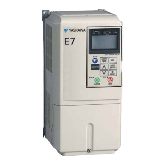
Component Names Models CIMR-E7U20P4 thru 2018 (25HP @ 208V/240V) and 40P4 thru 4018 (30HP @ 480V) The external appearance, component names, and terminal arrangement of the Drive are shown in Fig 1.4. and 1.5. Top protective cover Mounting hole Front cover Digital Operator Diecast Heat Sink Nameplate... - Page 17 Models CIMR-E7U2022 thru 2110 (30HP and above @ 208V/240V) and 4030 thru 4300 (40HP and above @ 480V) The external appearance, component names, and terminal arrangement of the Drive are shown in Fig 1.6 and 1.7. Mounting holes Mounting holes Drive cover Drive cover Cooling fan...
-
Page 18: Exterior And Mounting Dimensions
Exterior and Mounting Dimensions DIMENSIONS: E7 (NEMA 1) 208/240V (3.6-74.8 AMPS) 480V (1.8- 40.0 AMPS) FRONT VIEW SIDE VIEW MOUNTING HOLES FOR "A" SIZE SCREW 1.38 DIA. (2) HOLES SIZE "J" .87 DIA. BOTTOM VIEW RATED DIMENSIONS IN INCHES MODEL APPROX. - Page 19 DIMENSIONS: E7 (NEMA 1) 208/240V (88.0-115 AMPS) 480V (52.0-125 AMPS) APPROX. WEIGHT CURRENT (LBS.) Physical Installation 1 - 8 Artisan Technology Group - Quality Instrumentation ... Guaranteed | (888) 88-SOURCE | www.artisantg.com...
- Page 20 208-230V (162-415 AMPS) DIMENSIONS: E7 (PROTECTED CHASSIS) 480V (156-304 AMPS) FRONT VIEW MOUNTING HOLES FOR "A" SIZE SCREW RATED DIMENSIONS IN INCHES APPROX. OUTPUT RATED MODEL NOM. WEIGHT CURRENT INPUT CIMR-E7U MOUNTING (LBS.) (AMPS) 20370 22.64 9.84 23.62 14.76 2.46 11.81 3.94 20450...
- Page 21 DIMENSIONS: E7 (PROTECTED CHASSIS) MOUNTING HOLES FOR "A" SIZE SCREWS RATED DIMENSIONS IN INCHES APPROX. OUTPUT RATED MODEL NOM. WEIGHT CURRENT MOUNTING INPUT CIMR-E7U (LBS.) (AMPS) 41850 300-350 50.00 10.63 51.38 27.95 3.35 16.34 4.94 42200 400-450 50.00 10.63 51.38 27.95 3.35 16.34...
-
Page 22: Heat Loss Data
Heat Loss Data Table 1.3 200V Class Heat Loss Data Drive Rated Total Cooling Internal TYPE (Inverter) Output Watt Cooling Fin Side Unit Side CIMR-E7U Capacity Current Loss Method (kVA) 20P4 Self 20P7 Self 21P5 Self 22P2 10.8 Self 23P7 16.8 25P5 27P5... - Page 23 Table 1.4 400V Class Heat Loss Data Drive Rated Total Cooling Internal TYPE (Inverter) Output Watt Cooling Fin Side Unit Side CIMR-E7U Capacity Current Loss Method (kVA) 40P4 Self 40P7 Self 41P5 Self 42P2 43P7 44P0 45P5 12.5 47P5 49P0 4011 4015 4018...
-
Page 24: Checking And Controlling The Installation Site
Checking and Controlling the Installation Site Install the Drive as described below and maintain optimum conditions. The Drive heatsink temperature may exceed 158°F (70°C). Therefore, mount the Drive to a surface suitable WARNING for high temperature. Installation Site Locate the E7 Drive as close as possible to the motor. Install the Drive under the following conditions in UL Pollution Degree 1 &... -
Page 25: Installation Orientation And Clearances
Installation Orientation and Clearances Install the Drive vertically so as not to reduce the cooling efficiency. When installing the Drive, always provide the following installation clearances to allow normal heat dissipation. For 3HP, 208V/240V (CIMR-E7U22P2 and below) or 2HP, 480V (CIMR-E7U41P5 and below), ensure that the heatsink is against a closed surface to avoid diverting cooling air around the heatsink. -
Page 26: Removing And Attaching The Terminal Cover
Removing and Attaching the Terminal Cover Remove the terminal cover to connect cables to the control circuit and main circuit terminals. Prior to removing any protective cover or wiring any part of the Drive, remove all power sources, including main input power and control circuit power. Wait a minimum of 5 minutes after power removal, before WARNING removing any cover. -
Page 27: Removing/Attaching The Digital Operator And Front Cover
Removing/Attaching the Digital Operator and Front Cover Models CIMR-E7U20P4 thru 2018 (0.5HP to 25HP @ 208V/240V) and 40P4 thru 4018 (0.5HP to 30HP @ 480V) For Models CIMR-E7U2018/4018 and smaller, remove the terminal cover and then use the following procedures to remove the Digital Operator and front cover. - Page 28 Models CIMR-E7U2022 thru 2110 (30HP to 150HP @ 208V/240V) and 4030 thru 4300 (40HP to 500HP @ 480V) For Models CIMR-E7U2022/4030 and larger, remove the terminal cover and then use the following procedures to remove the Digital Operator and front cover. Removing the Digital Operator Use the same procedure for Models CIMR-E7U2018/4018 and smaller.
- Page 29 Attaching the Digital Operator After attaching the front cover, mount the Digital Operator onto the Drive using the following procedure. Hook the Digital Operator at A (two locations) on the front cover by moving in the direction of arrow 1 as shown in the following illustration.
-
Page 30: Chapter 2 - Electrical Installation
Chapter 2 Electrical Installation This chapter describes wiring terminals, main circuit terminal connections, main circuit terminal wiring specifications, control circuit terminals, and control circuit wiring specifications. Terminal Block Configuration ............. 2-2 Wiring Main Circuit Terminals ........... 2-3 Control Wiring................2-12 Electrical Installation 2 - 1 Artisan Technology Group - Quality Instrumentation ... -
Page 31: Terminal Block Configuration
Terminal Block Configuration The wiring terminals are shown in Fig 2.1. E(G) E(G) Control circuit terminals Main circuit terminals Charge indicator Ground terminal Ground terminal Models CIMR-_ _ _2018 (25 HP, 208V)/ 4018 (30 HP, 480V) and smaller E(G) E(G) Control circuit terminals Charge indicator Main circuit terminals... -
Page 32: Wiring Main Circuit Terminals
Wiring Main Circuit Terminals Applicable Wire Sizes and Closed-loop Connectors Select the appropriate wires and crimp terminals from Table 2.1 to Table 2.2. Table 2.1 208-240Vac Wire Sizes and Connector Specifications Recommended Clamping Wire Size Drive Model Nominal Terminal Torque Wire Terminal Symbol CIMR-E7U... - Page 33 Table 2.1 208-240Vac Wire Sizes and Connector Specifications Recommended Clamping Wire Size Drive Model Nominal Terminal Torque Wire Terminal Symbol CIMR-E7U Screws lb. in. Type (N•m) R/L1, S/L2, T/L3, 1 U/T1, (22.5) (100) V/T2, W/T3, R1/L11, S1/L21, T1/L31 88.5 (10.0) (22) 2037 203.6...
- Page 34 Table 2.2 480Vac Wire Sizes and Connector Specifications Clamping Recommended Drive Model Nominal Terminal Torque Wire Size AWG Terminal Symbol Wire Type CIMR-E7U Screws lb. in. (N•m) R/L1, S/L2, T/L3, 13.3 B1, B2, U/T1, V/T2, W/T3 40P4 0.5/0.75 (1.5) (2.1) R/L1, S/L2, T/L3, 13.3 B1, B2, U/T1, V/T2, W/T3...
- Page 35 Table 2.2 480Vac Wire Sizes and Connector Specifications Clamping Recommended Drive Model Nominal Terminal Torque Wire Size AWG Terminal Symbol Wire Type CIMR-E7U Screws lb. in. (N•m) 88.5 R/L1, S/L2, T/L3, 1, U/T1, V/T2, (10.0) (33.6) W/T3, R1/L11, S1/L21, T1/L31 44.3 4055 (5.0)
- Page 36 Table 2.2 480Vac Wire Sizes and Connector Specifications Clamping Recommended Drive Model Nominal Terminal Torque Wire Size AWG Terminal Symbol Wire Type CIMR-E7U Screws lb. in. (N•m) 88.5 300 X 2P R/L1, S/L2, T/L3, (10.0) (152 X 2P) 88.5 300 X 2P U/T1, V/T2, W/T3, R1/L11, S1/L21, T1/L33 (10.0) (152 X 2P)
- Page 37 Main Circuit Terminal Functions Main circuit terminal functions are summarized according to terminal symbols in Table 2.3. Wire the terminals correctly for the desired purpose. Table 2.3 Main Circuit Terminal Functions (208-240Vac and 480Vac) Model: CIMR-E7U _ _ _ _ Purpose Terminal Designation 208-240Vac...
- Page 38 2. Control power is supplied internally from the main circuit DC power supply for all Drives. 3. Consult your Yaskawa representative before using 12-pulse rectification. Electrical Installation 2 - 9 Artisan Technology Group - Quality Instrumentation ... Guaranteed | (888) 88-SOURCE | www.artisantg.com...
- Page 39 2. Control power is supplied internally from the main circuit DC power supply for all Drives. 3. Consult your Yaskawa representative before using 12-pulse rectification. Electrical Installation 2 - 10 Artisan Technology Group - Quality Instrumentation ... Guaranteed | (888) 88-SOURCE | www.artisantg.com...
- Page 40 Cable Length between Drive and Motor The E7 should be installed as close as possible to the motor to minimize the length of load side power cable needed between the Drive and the motor. If the cable between the Drive and the motor is long, the high-frequency leakage current will increase, causing the Drive output current to increase as well.
-
Page 41: Control Wiring
(0.5 to 2 Use shielded twisted-pair cables to input an external speed command. Yaskawa recommends using straight solderless terminals on digital inputs to simplify wiring and improve reliability. Yaskawa recommends using a thin-slot screwdriver with a 3.5 mm blade width. - Page 42 Wiring Checks After all wiring is completed, perform the following checks: Is all wiring correct? Have all wire clippings, screws or other foreign material been removed from the Drive enclosure? Are all terminal screws tight? Electrical Installation 2 - 13 Artisan Technology Group - Quality Instrumentation ...
- Page 43 Control Circuit Terminal Functions The factory default functions of the control circuit terminals for 2-wire control are shown in Table 2.8. Table 2.8 Control Circuit Terminals Type Signal Name Description Signal Level Forward run/stop command Forward run when CLOSED; stopped when OPEN. Reverse run/stop command Reverse run when CLOSED;...
- Page 44 DIP Switch S1 DIP Switch S1 is described in this section. The functions of DIP switch S1 are shown in Table 2.9. Terminating resistance DIP Switch S1 located on terminal board. Fig 2.4 DIP Switch S1 Location Table 2.9 DIP Switch S1 Name Function Setting...
- Page 45 Shunt Connector CN15 The shunt connector CN15 is described in this section. Shunt connector along with parameters H4-07 and H4-08 select the sig- nal range of the analog output terminals FM and AM. Shunt connector CN15 is only available when the optional Terminal Card with the 4-20mA Analog Output Monitor is installed (Model No.
- Page 46 Sinking/Sourcing Mode The input terminal logic can be switched between sinking mode (0V common) and sourcing mode (+24V common) by using the terminals SN, SC, and SP. An external power supply can also be connected, providing more freedom in signal input methods.
- Page 47 Terminal Connections Connections to Drive terminals are shown in Fig 2.6. Fig 2.6 Terminal Connections Electrical Installation 2 - 18 Artisan Technology Group - Quality Instrumentation ... Guaranteed | (888) 88-SOURCE | www.artisantg.com...
- Page 48 Control Circuit Wiring Precautions Observe the following precautions when wiring control circuits: Separate control wiring from power/motor wiring (terminals R/L1, S/L2, T/L3, U/T1, V/T2, W/T3, 2, and 3) and other high-power lines. Separate wiring for control circuit terminals MA, MB, MC, M1, M2, M3, and M4 (digital outputs) from wiring to other control circuit terminals.
- Page 49 Field Wiring Diagram Use this diagram to document field wiring. It may be helpful to copy this page. Fig 2.8 Field Wiring Diagram Electrical Installation 2 - 20 Artisan Technology Group - Quality Instrumentation ... Guaranteed | (888) 88-SOURCE | www.artisantg.com...
- Page 50 Chapter 3 Digital Operator This chapter describes the displays and functions of the Digital Operator. Digital Operator Display ............. 3-2 Digital Operator Keys..............3-3 Drive Mode Indicators ..............3-5 Drive Main Menu................ 3-7 Quick Setting Menu (-QUICK-) ..........3-12 Programming Menu (-ADV-) ............ 3-13 Example of Changing a Parameter..........
-
Page 51: Digital Operator Display
Digital Operator Display The Digital Operator is used for programming, operating, and monitoring drive operation. By default the E7 Drive will not run unless the digital operator is securely attached to the Drive. The various items included on the Digital Operator are described below. Drive Mode Indicators See Table 3.2 Menu Display... -
Page 52: Digital Operator Keys
Digital Operator Keys The names and functions of the Digital Operator Keys are described in Table 3.1. Table 3.1 Digital Operator Keys Name Function • Pressing the AUTO key will put the Drive in the “Auto” mode. • In the “Auto” mode, the Drive will be capable of starting/stopping depending on the setting of parameter “b1-02”... - Page 53 Table 3.1 Digital Operator Keys Name Function • Pressing the HAND key will put the Drive in the “Hand” mode and start the Drive. • In the “Hand” mode, the drive speed command will depend on the setting of parameter “b1-12” (Hand Frequency Reference Selection). HAND Key •...
-
Page 54: Drive Mode Indicators
Drive Mode Indicators The definition of the Drive mode indicators are shown in Table 3.2. Table 3.2 Drive Mode Indicators Indicator Definition Lit when a forward run command is input and when Drive is in “Hand” Mode. Lit when a reverse run command is input. AUTO SEQ Lit when set up for remote run command. - Page 55 AUTO Reference (REF) Indicator The status of the AUTO “Reference” (REF) indicator is shown in Table 3.4. This indicator is always “Off” when the Drive is in the “Hand” mode. When the Drive is in the “Auto” mode, the REF indicator status is dependent on the setting of parameter “b1-01”...
-
Page 56: Drive Main Menu
Drive Main Menu The Drive’s parameters and monitoring functions are organized into menu groups that make it easier to read and set parameters. The Drive is equipped with five menu selections. The five selections and their primary functions are shown in Table 3.7 and are directly available by pressing the MENU key. - Page 57 Main Menu Structure The menu selection display will appear when the MENU key is pressed from a monitor or setting display. While viewing the menu selection display, press the MENU key repeatedly to scroll between the menu selections. -DRIVE- ** Main Menu ** - - - - - - - - - - - - - - Operation -DRIVE-...
- Page 58 Operation Menu (-DRIVE-) This menu is used for setting a speed command or monitoring values such as output frequency and output current. It is also used for displaying the fault history and the fault traces. The Drive must be in this menu in order to run, see parameter b1-08.
- Page 59 U2 Fault Trace List After viewing the “Monitor” parameter list, in order to view the “Fault Trace” parameter list, follow the key operations below (Fig 3.4). -DRIVE- -DRIVE- -DRIVE- Monitor Fault Trace Current Fault U1-01= 0.00Hz U2-01= None U2-01= None - - - - - - - - - - - - - - - - - - - - - - - - - - - - - - - - - - - - - - - - - - - - - - - - - - - - - - - - - - - -...
- Page 60 U3 Fault History List After viewing the “Fault Trace” parameter list, in order to view the “Fault History” parameter list, follow the key operations below Fig 3.5). -DRIVE- -DRIVE- -DRIVE- Fault Trace Fault History Last Fault U2-01= None U3-01= None U3-01= None - - - - - - - - - - - - - - - - - - - -...
-
Page 61: Quick Setting Menu (-Quick-)
Quick Setting Menu (-QUICK-) This menu is used to set/read the most commonly used parameters in the Drive. Follow the key operations below (Fig 3.6) to access the Quick Setting Menu: -QUICK- -QUICK- Reference Source ** Main Menu ** - - - - - - - - - - - - - - - - - - - - - - - - - - - - - - - - - - B1-01= Quick Setting... -
Page 62: Programming Menu (-Adv-)
Programming Menu (-ADV-) This menu is used to set/read every parameter in the Drive. Follow the key operations below (Fig 3.7) to access the Program- ming Menu. -ADV- -ADV- Initialization ** Main Menu ** - - - - - - - - - - - - - - - - - - - - - - - - - - - - - - - - - - A1-00= Programming... - Page 63 Modified Constants Menu (-VERIFY-) This menu is used to set/read the parameters that have been modified from their original factory default settings. Follow the key operations below (Fig 3.8) to access the Modified Constants Parameter Menu. -VERIFY- ** Main Menu ** See Note 1 See Note 1 - - - - - - - - - - - - - -...
-
Page 64: Example Of Changing A Parameter
Example of Changing a Parameter Table 3.14 provides an example of how to change parameter “C1-02” (Deceleration Time 1) from 30 seconds to 40 seconds. Table 3.14 Changing a Parameter in the Programming Menu Step Digital Operator Display Description Number -DRIVE- Frequency Ref The Drive is first powered up. - Page 65 Table 3.14 Changing a Parameter in the Programming Menu Step Digital Operator Display Description Number -ADV- Decel Time 1 - - - - - - - - - - - - - - - - - - - - Press the INCREASE key to display C1-02 (Decel Time 1). C1-02= 30.0sec (0.0~6000.0)
-
Page 66: Chapter 4 - Start Up
Chapter 4 Start Up This chapter describes the procedures to prepare the Drive for start up and the procedures to conduct a Drive start up. Drive Start Up Preparation............4-2 Drive Start Up Procedures............4-5 Start Up 4 - 1 Artisan Technology Group - Quality Instrumentation ... -
Page 67: Drive Start Up Preparation
1. The Drive is thoroughly tested at the factory. The start up person should verify that the drive is free of shipping and installation damage. Shipping damage is not covered by the Yaskawa warranty. Claims must be filed with the shipping company as soon as possible for any potential recovery via insurance. - Page 68 If lead length must exceed this distance, reduce the carrier frequency (See Table 2.6) and consult Yaskawa toll free at 1-800-YASKAWA (927-5292) for other motor protection measures. 14. Signal and control leads must be separated from main circuit leads (R/L1, S/L2, T/L3, U/T1, V/T2, W/T3).
- Page 69 23. Wire all necessary power leads to the Drive. DO NOT CONNECT MOTOR TO DRIVE YET. 24. Wire all necessary ground wires to the Drive. 25. Wire all necessary control wires to the Drive. 26. Ensure that the power leads are connected to the R/L1, S/L2 and T/L3 terminals in the Drive. 27.
-
Page 70: Drive Start Up Procedures
Drive Start Up Procedures 1. Confirm that all three phases are present and that the input voltage is correct for the Drive being set up. Measure the voltage on the line side of the Drives Molded Case Circuit Breaker/disconnect and record below. Table 4.1 Input Voltage Check Measurement Location Voltage (Vac) - Page 71 Table 4.2 Input Voltage Setting Parameter Parameter Name Setting Range Factory Setting Menu Location Digital Operator Display 155.0 to 255.0 240.0 Quick Setting (208-240Vac) (208-240Vac) Input Voltage Setting E1-01 Input Voltage 310.0 to 510.0 480.0 Programming (480Vac) (480Vac) Ensure the DATA/ENTER key is pressed to enter the selection in the Drive. “Entry Accepted” briefly appears and the display is now no longer flashing.
- Page 72 Table 4.5 Speed Command Selection Parameter Parameter Name Setting Setting Factory Menu Location Digital Operator Display Choices Range Setting 0: Operator Frequency Reference Quick Setting 1: Terminals b1-01 Selection 0 - 3 2: Serial Com Reference Source Programming 3: Option PCB Ensure the DATA/ENTER key is pressed to enter the selection in the Drive.
- Page 73 and ▼ keys to view Output Current (U1-03), 18. Press the MONITOR key to display the U1 monitors. Use the Output Voltage (U1-06), and DC Bus Voltage (U1-07) while running the Drive throughout its entire speed range. Record the following information at each speed: Frequency Output Current Output Voltage...
- Page 74 21. Check the signal for proper polarity. Observe if the speed command can achieve the minimum and maximum speeds desired. If not, perform the following: For 0-10Vdc input (Terminal A1) With no input, adjust Bias (H3-03 setting) until an output of “0.0 Hz” is obtained. With full-scale input, adjust Gain (H3-02 setting) until an output of “60.0 Hz”...
- Page 75 Notes: Start Up 4 - 10 Artisan Technology Group - Quality Instrumentation ... Guaranteed | (888) 88-SOURCE | www.artisantg.com...
- Page 76 Chapter 5 Basic Programming This Manual contains descriptions of all user accessible parameters contained in the Drive. Parameters are listed in alpha-numerical order. Parameter number and name, along with a detailed description and its settings are described on the following pages. A1 Initialization................
-
Page 77: A1 Initialization
E7 Basic Programming Parameters The initialization group contains parameters associated with initial set-up of the Drive. Parameters involving the display language, access levels, initialization and password are located in this group. A1 Initialization A1-00 Select Language Setting Description English (factory default) Japanese Deutsch Francais... - Page 78 If A1-01 is configured for Advanced Access (A1-01= “2: Advanced Level”), then all menus and all parameters are shown. If the Access Level Selection is set to Advanced, all parameters should be adjustable unless: The Drive parameters are password protected (A1-04) which will prevent access to A1-00 through A1-03 and all A2 parameters.
-
Page 79: B1 Sequence
b1 Sequence The Sequence Group contains parameters associated with starting and stopping the Drive. Parameters involving the Run Command, Speed Reference location, Stopping Method and Hand/Auto changeover are located in this group. b1-01 Reference (Speed Command) Source Selection Setting Description Operator - Digital Preset Speed d1-01 Terminals - Analog Input Terminal A1 (or Terminal A2, see Parameter H3-13) Serial Com - RS-485 Terminals R+, R-, S+ and S-... - Page 80 To successfully operate the Drive remotely, an external run command must be received by the Drive. Parameter b1-02 specifies from where the run command will be accepted. Although the Run Source and the Reference Source (b1-01) are normally taken from the same source (e.g. digital operator, terminals or serial communication), this is not always the case.
- Page 81 If b1-01= “3: Option PCB” but a network card is not installed in 2CN, an “OPE05” operator programming IMPORTANT error will be displayed on the digital operator and the Drive will not run. b1-03 Stopping Method There are four methods of stopping the Drive when the Run command is removed. Setting Description Ramp to Stop (factory default)
- Page 82 (CLOSED) Run Command (OPEN) 100 % Motor Speed Output Frequency Drive Output Frequency Interrupted TIME Fig 5.5 Coast to Stop After a stop is initiated, a subsequent Run commands input before the Minimum Baseblock Time (L2-03) IMPORTANT has expired, will be ignored. 2: DCInj to Stop: When the Run command is removed, the Drive will Baseblock (turn off its output) for the Minimum Baseblock Time (L2-03).
- Page 83 Ignored Run Command (CLOSED) Run Command Deceleration Time (C1-02) (OPEN) 100 % Minimum Drive Output Baseblock Voltage Output Frequency Time (L2-03) Interrupted Minimum 100% (Maximum Output Output Frequency Frequency) Timer Value T Timer Value T Output Frequency at Stop Command Input (C1-02) Fig 5.7 Coast to Stop with Timer b1-04 Reverse Operation...
- Page 84 When switching from local mode to Auto mode when b1-07=“1: Accept Extrn Run” the Drive may start IMPORTANT unexpectedly if the Run command is already applied. Be sure all personnel are clear of rotating machinery and electrical connections prior to switching between local mode and Auto mode. b1-08 Run Command Selection During Programming Setting Description...
-
Page 85: B2 Dc Braking
b1-11 Drive Delay Time Setting Setting Range: 0 to 600 Seconds Factory Default: 0 Seconds If a time is set into parameter b1-11, the Drive will delay executing any run command until the b1-11 time has expired. During Drive delay time execution, the digital operator will display: DDLY Waiting to RUN Both the ALARM and Run indicators will blink while the Drive waits to execute the Run command. - Page 86 DC injection b2-01 Output Frequency b2-04 Fig 5.8 DC Injection Braking During Stopping b2-02 DC Injection Braking Current Setting Range: 0 to 100% Factory Default: 50% The level of DC Injection Braking Current affects the strength of the magnetic field attempting to lock the motor shaft. Increasing the level of current will increase the amount of heat generated by the motor windings and should only be increased to the level necessary to hold the motor shaft.
-
Page 87: B3 Speed Search
b2-09 Motor Pre-Heat Current Setting Range: 0 to 100% Factory Default: 0% A DC current can be circulated within the motor windings while the motor is stopped. The current will produce heat within the motor and prevent condensation. Parameter b2-09 determines the percentage of Drive rated output current that will be used for the motor pre-heat function. - Page 88 The speed estimation mode cannot be used when there are multiple motors operated by one Drive or the IMPORTANT motor is two or more frames smaller than the standard size motor per the Drive capacity. AC power supply Set frequency Start using reference speed detected...
- Page 89 If a UV1 fault occurs when current detection Speed Search is attempted, increase the setting of L2-04 IMPORTANT IMPORTANT If an OC fault occurs when Speed Search is attempted after power loss recovery, increase the setting of L2-03. Deceleration time set in b3-03 Run command Maximum output Set frequency...
- Page 90 Setting of Automatic Speed Search for Speed Search Method b3-01 all RUN commands and Used for Multi-function momentary power loss inputs Speed Estimation Yes - Speed Estimation Current Detection Yes - Current Detection b3-02 Speed Search Deactivation Current Setting Range: 0 to 200% of Drive rated output current Factory Default: 120% of Drive rated output current When using the current detection method of Speed Search, parameter b3-02 sets the current level that will determine when the search is complete and the rotor and output speeds match.
-
Page 91: B5 Pi Function
b5 PI Function The capability to accept an analog signal as feedback for a PI (Proportional + Integral) control function is built into the Drive. D1-04 Frequency Reference using multi-step Sleep function command selection b5-21 D1-02 b5-16 b1-01 on/off Delay Frequency reference D1-01 b5-01=0... - Page 92 In some situations there are two feedback inputs. Air handling unit return fan speed control in a “volume matching” strategy for building pressure control is an example. The drive can be programmed to maintain a set differential between two analog signals. If input A2 is configured as a “PI Differential Mode”...
- Page 93 b5-04 Integral Limit Setting Setting Range: 0.0 to 100.0% Factory Default: 100.0% On some applications, especially those with rapidly varying loads, the output of the PI function may have large oscillations. To suppress these oscillations, a limit can be applied to the integral factor by programming b5-04. b5-06 PI Output Limit Setting Range: 0.0 to 100.0% Factory Default: 100.0%...
- Page 94 b5-10 PI Output Gain Setting Setting Range: 0.0 to 25.0 Factory Default: 1.0 Applies a multiplier to the output of the PI function. Using the gain can be helpful when the PI function is used to trim the Speed Command. Increasing b5-10 causes the PI function to have a greater regulating affect on the speed command. b5-11 PI Reverse Selection Setting Description...
- Page 95 b5-15 Sleep Function Start Level Setting Range: 0.0 to 200.0 Hz Factory Default: 0.0 Hz b5-16 Sleep Delay Time Setting Range: 0.0 to 25.5 Seconds Factory Default: 0.0 Seconds The Sleep Function can be programmed to prevent running the Drive when the PI loop output or the speed command is so low that no usable work is being done and/or equipment damage may result.
- Page 96 In order to use parameter b5-19 as the PI Setpoint, set parameter b5-18= “1: Enabled”. If b5-18= “0: Disabled” the PI Setpoint will either be: • Modbus Register 06H (If Register 0FH bit 1 is high) • The active speed command (i.e. Determined by the setting of b1-01). See Table 1 “Setpoint Options” b5-19 PI Setpoint Value Setting Range: (dependant on parameter b5-20) B5-19 Setting Range Example:...
- Page 97 For example: If b5-20= 10425 then at 100% setpoint/feedback the digital operator would display 42.5 for monitor U1-38 or U1-24. b5-21 Sleep Source Setting Description SFS Input (Output of PI block) PI Setpoint (factory default) Snooze Parameter b5-21 selects the sleep function characteristic action: When b5-21= “0: SFS Input”...
- Page 98 Just before the Snooze Function is activated, the PI Setpoint can be temporarily increased to create an overshoot of the intended PI Setpoint. The temporary boost is determined by the PI Setpoint Boost Setting (b5-25). Once the temporary boost level is reached (or the PI Maximum Boost Time (b5-26) is exceeded), the Drive output shuts off (snoozes) and the intended PI Setpoint returns.
- Page 99 b5-28 PI Feedback Square Root Function Activation Setting Description Disabled (factory default) Enabled If b5-28= “1: Enabled”, the square root of the PI feedback is compared to the PI Setpoint in order to determine appropriate Drive output to properly regulate the system. This is helpful in cases where the measured feedback is pressure but the PI loop needs to regulate flow.
-
Page 100: B8 Energy Savings
b8 Energy Savings The energy savings function improves overall system operating efficiency by operating the motor at its highest efficiency. This is accomplished by continuously monitoring the motor load and adjusting the motor terminal voltage so that the motor always operates near its rated slip frequency. -
Page 101: C1 Accel/Decel
C1 Accel/Decel C1-01 Acceleration Time 1 C1-02 Deceleration Time 1 C1-03 Acceleration Time 2 C1-04 Deceleration Time 2 Setting Range: 0.0 to 6000.0 Seconds Factory Default: 30.0 Seconds C1-01 (Acceleration Time 1) sets the time to accelerate from zero to maximum speed (E1-04). C1-02 (Deceleration Time 1) sets the time to decelerate from maximum speed to zero. -
Page 102: D2 Reference (Speed Command) Limits
d2 Reference (Speed Command) Limits d2-01 Frequency Reference Upper Limit Setting Range: 0.0 to 110.0% Factory Default: 100.0% d2-02 Frequency Reference Lower Limit Setting Range: 0.0 to 110.0% Factory Default: 0.0% The use of parameters d2-01 and d2-02 places limitations on the speed command that the Drive will accept. The parameters are set in units of percentage of the maximum frequency (E1-04) and provide limits on any remote speed command input. -
Page 103: D3 Jump Frequencies
d3 Jump Frequencies d3-01 Jump Frequency 1 d3-02 Jump Frequency 2 d3-03 Jump Frequency 3 Setting Range: 0.0 to 200.0 Hz Factory Default: 0.0 Hz d3-04 Jump Frequency Width Setting Range: 0.0 to 20.0 Hz Factory Default: 1.0 Hz In order to avoid continuous operation at a speed that causes resonance in driven machinery, the Drive can be programmed with jump frequencies that will not allow continued operation within specific frequency ranges. -
Page 104: E1 V/F Pattern
E1 V/f Pattern E1-01 Input Voltage Setting Setting Range: 155.0V to 255.0V (208V/240V Models) 310.0V to 510.0V (480V Models) Factory Defaults: 208.0V (208V Models) 240.0V (240V Models) 480.0V (480V Models) Set the Input Voltage parameter (E1-01) to the nominal voltage of the connected AC power supply. This parameter adjusts the levels of some protective features of the Drive (i.e. - Page 105 Table 3 Preset V/f Patterns Specifications E1-03 V/f Pattern *1 Specifications E1-03 V/f Pattern *1 High Starting Torque 1 50Hz 50Hz High (Hz) (Hz) Starting 0 1.3 2.5 0 1.3 2.5 Torque 2 High 60Hz Saturation Starting Torque 1 60Hz High 50Hz Saturation Starting...
- Page 106 E1-05 Maximum Output Voltage Setting Range: 0.0 to 255.0V (240V Models) 0.0 to 510.0V (480V Models) Factory Defaults: 240.0V (240V Models) 480.0V (480V Models) E1-06 Base Frequency Setting Range: 0.0 to 200.0 Hz (settings above 120.0 Hz are currently not supported) Factory Default: 60.0 Hz E1-07 Mid Output Frequency A Setting Range:...
-
Page 107: E2 Motor Setup
To set up a custom V/f pattern, program the points shown in the diagram below using parameters E1-04 through E1-13. Be sure that the following condition is true: E1-09 ≤ E1-07 ≤ E1-06 ≤ E1-11 ≤ E1-04 Max Voltage E1-05 Mid Voltage B E1-12 Base Voltage E1-13 Mid Voltage A E1-08... -
Page 108: F6 Com Opt Setup (Applies Only To The Lonworks Option)
E2-03 No Load Current Setting Range: Model Dependent (see Appendix B) Factory Default: Model Dependent Set E2-03 to the motor no-load current at rated voltage and rated frequency. Consult the motor manufacturer for the proper value if the no load current is not stated on the motor nameplate. F6 Com OPT Setup (applies only to the LonWorks option) F6-01 Operation Selection After Communication Error Setting... -
Page 109: H3 Analog Inputs
F6-05 Current Scaling via Communication Option PCB Setting Description A Display (factory default) 100%/8192 (Drive Rated Current) A communication option card can read the Drive’s DPRAM to access the current monitor. The format of the current reading in the DPRAM will be determined by parameter F6-05. F6-05= “0: A Display”... - Page 110 Gain =200% 100% Bias = 0% 12mA 20mA Analog Input Level Analog Input Signal Fig 5.24 Output Frequency as Commanded via Analog Input with Increased Gain Setting Adjustment of the bias setting will likewise adjust the speed command that is equivalent to the minimum analog input level (0Vdc or 4mA).
- Page 111 H3-08 Terminal A2 Signal Level Setting Description 0 - 10VDC 4 - 20mA (Default) The H3-08 parameter (Terminal A2 Signal Level) allows the programmer to specify the signal that will be applied to the A2 analog input. The A2 analog input can accept either a 0–10 Vdc or 4-20 mA signal as a reference. The Drive also has a DIP switch (S1) on the removable terminal board that must be set for the proper reference signal into the A2 analog input.
- Page 112 H3-09 Terminal A2 Function Selection Setting Description Frequency Bias Aux Reference (factory default) PI Feedback Frequency Bias 2 Motor Temperature PI Differential Not Used The A2 analog input can be programmed to perform many different functions. The setting of parameter H3-09 determines which of the following functions the A2 analog input will perform.
- Page 113 H3-02 H3-02 H3-03 H3-03 A1 Voltage A1 Voltage A1 Voltage Factory Default With H3-03 applied With both H3-03 and analog input bias (H3-09=0) applied Fig 5.29 Frequency Bias Applied to Analog Speed Command Function: Aux Reference Setting: 2 In order for the A2 analog input to be used as the master Speed Command, parameter H3-09 must be set for Aux Reference (H3-09= “2: Aux Reference”).
- Page 114 Function: PI Differential Setting: 16 Normal PI operation will adjust the Drive output in order to match the measured feedback value to a desired setpoint. When PI is operated in the differential mode, however, the Drive output is adjusted in order to maintain a desired differential between two feedback signals.
-
Page 115: L2 Momentary Power Loss Ride-Thru Function
Analog Input Filter input Internal Analog Input Valve Analog Noisy signal (Filtered) input post Fig 5.31 Analog Input Filter Time Constant Effect on “Noisy” Signal H3-13 Master Frequency Reference Terminal Selection Setting Description Main Fref= A1(factory default) Main Fref= A2 Parameter H3-13 allows the programmer to select which analog input will serve as the Speed Command input when “Terminals”... -
Page 116: L3 Stall Prevention
If L2-01= “1: PwrL Ride Thru t”, the Drive restarts without the UV1 fault if power is returned within the time specified in L2-02, the Momentary Power Loss Ride-thru Time. During the power loss but before the fault trip, the digital operator will display a UV alarm. - Page 117 Stall level during acceleration -15% Output Current Time Output frequency Output frequency is controlled to prevent the motor stalling. Time Fig 5.32 Detailed Time Chart for Stall Prevention During Acceleration If L3-01= “2: Intelligent”, the intelligent stall prevention is enabled. The active acceleration time is ignored and the Drive will attempt to accelerate as quickly as possible without exceeding the L3-02 output current level.
- Page 118 L3-04 Stall Prevention Selection During Decel Setting Description Disabled General Purpose (factory default) Intelligent Stall prev w/R The stall prevention during deceleration function adjusts the deceleration time in order to prevent OV fault trips during deceleration. If L3-04= “0: Disabled”, stall prevention is disabled and if the load is large and the deceleration time short enough the Drive may fault and stop.
- Page 119 L3-06 Stall Prevention Level During Running Setting Range: 30 to 200% of Drive rated output current Factory Default: 20% of Drive rated output current The Stall Prevention During Running function will attempt to avoid a Drive OC fault occurrence while the Drive is operating at a constant speed.
-
Page 120: L4 Speed Command Loss Detection
L4 Speed Command Loss Detection L4-01 Speed Agreement Detection Level Setting Range: 0.0 to 200.0 Hz Factory Default: 0.0 Hz L4-02 Speed Agreement Detection Width Setting Range: 0.0 to 20.0 Hz Factory Default: 2.0 Hz Parameters L4-01 and L4-02 are user specified levels for use with the Fref/Fout Agree 1, Fref/Set Agree 1, and Freq Detect and 2 digital output functions. -
Page 121: L5 Fault Restart
L5 Fault Restart L5-01 Number of Auto Restart Attempts Setting Range: 0 to 10 Factory Default: 0 L5-02 Auto Restart Operation Selection Setting Description No Flt Relay (factory default) Flt Relay Active L5-03 Maximum Restart Time After Fault Setting Range: 0.5 to 600.0 Seconds Factory Default: 180.0 Seconds All major faults will cause the Drive to stop. - Page 122 The auto restart count is reset back to 0 if any of the following occur: • No further faults for ten minutes after the last retry. • The Drives power is turned off (the Drive must be without power long enough to let control power dissipate). •...
-
Page 123: L6 Torque Detection
L6 Torque Detection L6-01 Torque Detection Selection 1 Setting Description Disabled (factory default) OL@SpdAgree - Alm OL At Run -Alm OL@SpdAgree - Flt OL At Run - Flt UL@SpdAgree - Alm UL at Run - Alm UL@SpdAgree - Flt UL At Run - Flt L6-02 Torque Detection Level 1 Setting Range: 0 to 300% of Drive rated output current... - Page 124 After selecting the proper detection scheme the Torque Detection Level (L6-02) must be specified. If the current level read by the output current transformers rises above (overtorque) or drops below (undertorque) this level, and remains there for at least the Torque Detection Time (L6-03), then the Torque Detection Function will change the state of any digital output configured for Torque Detection (H2-01/H2-02= “B: Trq Det 1 N.O.”, or “17: Trq Det 1 N.C.”).
-
Page 125: L8 Hardware Protection
L8 Hardware Protection L8-02 Overheat Pre-Alarm Level Setting Range: 50 to 130 Factory Default: 95 L8-03 Overheat Pre-Alarm Operation Selection Setting Description Ramp to Stop (Decel Time C1-02) Coast to Stop Fast-Stop (Decel Time C1-09) Alarm Only OH Alarm and Reduce (factory default) The Drive is capable of warning the operator of an impending heatsink over-temperature fault via an OH pre-alarm. - Page 126 L8-09 Output Ground Fault Detection Selection Setting Description Disabled Enabled (factory default) The Drive has a ground fault detection circuit that activates when the current to ground exceeds 50% of the Drive’s rated out- put current. The current to ground is determined by comparing the measured current on each of the output phases. If the cur- rent to ground is determined to be above 50% of the Drive’s rated output current the digital operator will display a GF and the Drive will coast to stop.
-
Page 127: O1 Monitor Configuration
o1 Monitor Configuration o1-01 User Monitor Selection Setting Range: 6 to 53 Factory Default: 6 Setting Description Output Voltage (factory default) DC Bus Voltage Output Power Input Terminal Status Output Terminal Status Drive Operation Status Cumulative Operation Time Software Number Terminal A1 Input Voltage Terminal A2 Input Voltage Motor Secondary Current (I... - Page 128 o1-02 Power-On Monitor Setting Description Frequency Reference (factory default) Output Frequency Output Current User Monitor (set by o1-01) When the Drive is powered up, three monitors are displayed on the digital operator. The first and largest monitor is the “Power-On” monitor. The factory default “Power-On monitor” is Speed Command (U1-01). Below the Speed Command monitor are the next two sequential monitors, Output Frequency (U1-02) and Output Current (U1-03).
- Page 129 o1-03 Digital Operator Display Scaling Setting Description Hz (factory default) 2 - 39 RPM (Enter the # of Motor Poles) 40 - 39999 User Display Parameter o1-03 allows the programmer to change the units in which the speed monitors and some speed parameters are displayed.
- Page 130 For example: If o1-03= 10425, then at full speed the digital operator will display “42.5”. Configuring parameter o1-03 for displaying in terms of an engineering unit is only appropriate if the actual display units have a linear relationship with the actual output speed.
-
Page 131: O2 Key Selections
o2 Key Selections o2-03 User Parameter Default Value Setting Description No Change Set Defaults Clear All The Drive gives the option of configuring any and all of the programming parameters and then saving the parameters as “User Initialization Values”. After configuring the Drive, set parameter o2-03= “1: Set Defaults”, to save the parameters to a User Initialization memory location. - Page 132 o2-06 Operation Selection when Digital Operator is Disconnected Setting Description Disabled Enabled (factory default) Leaving o2-06 enabled will cause the Drive to fault, when the digital operator is removed, even if it’s not outputting to the motor. The reset key on the digital operator will need to be pressed after reconnecting the digital operator to reset the fault and continue normal operation.
-
Page 133: O3 Digital Operator Copy Function
o3 Digital Operator Copy Function o3-01 Copy Function Selection Setting Description COPY SELECT (factory default) INV→OP READ OP→INV WRITE OP↔INV VERIFY Note: The copy function is disabled when serial communication is active. o3-02 Read Allowed Selection Setting Description Disabled (factory default) Enabled The digital operator has parameter COPY capabilities via built in non-volatile memory. - Page 134 -ADV- COPY OP→INV COPYING A successful COPY of the parameter values will display: -ADV- COPY COPY COMPLETE An error may occur while writing the parameter values to the Drive. If an error is displayed, press any key to cancel the error display and return to parameter o3-01.
- Page 135 • Software Number (e.g. 03011 also known as FLASH ID) Yaskawa offers DriveWizard™ software that can also READ, COPY, and VERIFY Drive parameter values. DriveWizard™ lists all discrepancies between the Drive and a pre-saved parameter file when verifying is performed.
-
Page 136: T1 Auto-Tuning
T1 Auto-Tuning Performing auto-tuning energizes the motor so that identification of key motor characteristics can be deter- mined. Output filters may affect the accuracy of measured characteristics, and/or result in drive damage. IMPORTANT Therefore, it may be necessary to remove output filters completely prior to executing tuning procedures. Consult the factory with questions regarding filter compatibility. - Page 137 Notes: Programming 5 - 62 Artisan Technology Group - Quality Instrumentation ... Guaranteed | (888) 88-SOURCE | www.artisantg.com...
- Page 138 Chapter 6 Diagnostics & Troubleshooting This chapter describes diagnostics and troubleshooting for the Drive. Fault Detection................6-2 Alarm Detection ................. 6-9 Operator Programming Errors (OPE) ........6-12 Auto-Tuning Faults..............6-13 Digital Operator COPY Function Faults ........6-14 Troubleshooting ............... 6-15 Main Circuit Test Procedure ............
-
Page 139: Fault Detection
Fault Detection When the Drive detects a fault, the fault information is displayed on the digital operator, the fault contact closes, and the motor coasts to stop. (However, a fault with selectable stopping method will operate according to the stopping method selected.) •... - Page 140 Table 6.1 Fault Displays and Processing Digital Description Cause Corrective Action Operator Display Perform a factory initialization Noise or spike on the control Cycle power off and on to the CPF04 CPU Internal A/D Converter Fault Internal A/D Err circuit input terminals Drive Replace the control board Perform a factory initialization...
- Page 141 Table 6.1 Fault Displays and Processing Digital Description Cause Corrective Action Operator Display Remove power to the Drive Connect the option board once more An option board is not correctly connected to the con- Perform a factory initialization Communication Option Card CPF23 trol board or an option board Interconnection Fault...
- Page 142 Table 6.1 Fault Displays and Processing Digital Description Cause Corrective Action Operator Display There is a broken wire in the output cable. Check the wiring to the motor. There is a broken wire in the Check the motor for phase to motor winding.
- Page 143 Table 6.1 Fault Displays and Processing Digital Description Cause Corrective Action Operator Display Recheck the cycle time and the size of the load Recheck the accel/decel time (C1-01 and C1-02) Motor Overheating Fault Overheating of motor as The Drive stops operation according to the Motor Overheat 2 measured by motor thermistor Recheck the V/F pattern (E1-01...
- Page 144 Table 6.1 Fault Displays and Processing Digital Description Cause Corrective Action Operator Display Open phase on input of the Drive Check the input voltage Loose terminal screws at Tighten the terminal screws R/L1, S/L2 or T/L3. Momentary power loss occurred Check the input voltage Input Phase Loss Input voltage fluctuation too large...
- Page 145 Table 6.1 Fault Displays and Processing Digital Description Cause Corrective Action Operator Display Cycle power off and on to the Drive Control Power Supply Undervoltage External load connected Repair or replace the Power PCB/ Undervoltage of the control circuit when CTL PS Undervolt pulling down the Drive power Gate Drive PCB...
-
Page 146: Alarm Detection
Alarm Detection Alarms are Drive protection functions that does not operate the fault contact. The Drive will automatically return to its original status once the cause of the alarm has been removed. During an alarm condition, the Digital Operator display flashes and an alarm output is generated at the multi-function outputs (H2-01 to H2-02) if programmed. - Page 147 Table 6.2 Alarm Displays and Processing Digital Description Cause Corrective Action Operator Display Verify Drive is programmed to receive the PI Feedback source signal Check to ensure the PI Feedback source is installed and working PI Feedback Loss properly This fault occurs when PI Feedback Loss PI Feedback source (e.g.
- Page 148 Table 6.2 Alarm Displays and Processing Digital Description Cause Corrective Action Operator Display Check the input circuit and High input voltage at R/L1, reduce the input power to within S/L2 and T/L3 specifications DC Bus Overvoltage The deceleration time is set too 208-240Vac: Trip point is ≥...
-
Page 149: Operator Programming Errors (Ope)
Operator Programming Errors (OPE) An Operator Programming Error (OPE) occurs when an inapplicable parameter is set or an individual parameter setting is inappropriate. The Drive does not operate until the parameter is set correctly. (Alarm output and fault contact do not operate.) If an OPE occurs, change the appropriate parameter by checking the cause shown in Table 6.3. -
Page 150: Auto-Tuning Faults
Auto-Tuning Faults Auto-tuning faults are shown below. When the following faults are detected, the fault is displayed on the digital operator and the motor coasts to a stop during operation. The fault contact is not activated. Table 6.4 Auto-Tuning Displays and Processing Digital Operator Display Probable Cause Corrective Action... -
Page 151: Digital Operator Copy Function Faults
Digital Operator COPY Function Faults These faults can occur occurred during the operator COPY function. Fault content is displayed on the operator. An error during the COPY function does not activate the fault contact output or alarm output. Table 6.5 Digital Operator COPY Function Faults Function Digital Operator Display Probable Causes... -
Page 152: Troubleshooting
Troubleshooting Due to parameter setting errors, faulty wiring, etc., the Drive and motor may not operate as expected when the system is started up. If this occurs, use this section as a reference and apply the appropriate measures. If a fault is displayed on the digital operator, refer to Fault Detection, Table 6.1. If Parameter Cannot Be Set Use the following information if a Drive parameter cannot be set. - Page 153 If the Motor Does Not Operate Use the following information if the motor does not operate. Ensure the digital operator is securely connected to the Drive. The motor does not operate when the HAND key on the Digital Operator is pressed. The following causes are possible: The Speed Command (Frequency Reference) is too low.
- Page 154 If the Motor Does Not Put Out Torque or If Acceleration is Slow Use the following information if the motor does not output torque or if acceleration is too slow. The stall prevention level during acceleration is too low. If the value set for L3-02 (Stall Prevention Acceleration Level) is too low, the acceleration time will be too long. Check to be sure that the set value is suitable.
- Page 155 If the Motor Overheats Take the following steps if the motor overheats. The load is too high. If the motor load is too high and the motor is used when the effective torque exceeds the motor's rated torque, the motor will overheat.
- Page 156 If a “Stand-alone” Ground Fault Interrupter Operates When the Drive is Run The Drive performs internal switching, so there is a certain amount of leakage current. This may cause an external ground fault interrupter to operate and cut off the power supply. Whenever possible, use a ground fault interrupter with a high leakage detection level (i.e., a sensitivity current of 200 mA or greater per Unit, with an operating time of 0.1 s or more), or one that incorporates high frequency countermeasures (i.e., one designed for use with Drives).
- Page 157 If the Motor Rotates Even When Drive Output is Stopped If the motor rotates even when the Drive is stopped, the DC injection braking may be insufficient. If the motor continues operating at low speed, without completely stopping after a stop has been executed, it means that the DC injection braking is not decelerating the motor enough.
-
Page 158: Main Circuit Test Procedure
Main Circuit Test Procedure Prior to removing any protective cover or wiring any part of the Drive, remove all power sources, including main input power and control circuit power. Wait a minimum of 5 minutes after power removal, before WARNING removing any cover. - Page 159 Table 6.6 Main Circuit Test Procedure Check Procedure (Continued from previous page) 11. Place the positive (red) meter lead on terminal ⊕ 1. Place the negative (black) meter lead on terminal R/L1. Expected reading is OL displayed. 12. Place the positive (red) meter lead on terminal ⊕ 1. Input Diodes Place the negative (black) meter lead on terminal S/L2.
- Page 160 Table 6.6 Main Circuit Test Procedure Check Procedure The output transistors are used to switch the DC bus voltage to allow current to flow to the motor. 1. Set a digital multi-meter to the Diode Check setting. 2. Place the positive (red) meter lead on terminal U/T1. Place the negative (black) meter lead on terminal ⊕...
- Page 161 Table 6.6 Main Circuit Test Procedure Check Procedure The Heat Sink & Internal Cooling Fans cool the heat sink as well as the output transistor mod- ules of the Drive. 1. Conduct a visual inspection to ensure the fan turns freely. 2.
-
Page 162: Drive Date Stamp Information
Drive Date Stamp Information This information is used to determine when a Drive was built to see if it is within its warranty period. The date stamp is located on the lower right side of the Drive. Fig 6.1 Date Stamp Location YEA Production Manufacture Date 00.7.22... - Page 163 Notes: Diagnostic & Troubleshooting 6 - 26 Artisan Technology Group - Quality Instrumentation ... Guaranteed | (888) 88-SOURCE | www.artisantg.com...
- Page 164 Chapter 7 Maintenance This chapter describes basic maintenance and inspection of the Drive. Please refer to these instructions to ensure that the Drive receives the proper maintenance to maintain overall performance. Periodic Inspection..............7-2 Preventive Maintenance ............7-3 Heatsink Cooling Fan Replacement .......... 7-4 Removing and Mounting the Terminal Card ......
-
Page 165: Periodic Inspection
Periodic Inspection Check the following items during periodic maintenance. • The motor should not be vibrating or making unusual noises. There should be no abnormal heat generation from the Drive or motor. • The ambient temperature should be within the Drive specification of -10 ° C to 40 ° C (14 ° F to 104 ° F). •... -
Page 166: Preventive Maintenance
Preventive Maintenance Table 7.3 Preventive Maintenance Inspection Points Item Check Points Every 3-6 Months Yearly Ambient Temperature Humidity Environment Dust Harmful Gas General Oil Mist Equipment Abnormal vibration or noise AC Power Supply Main circuit & control voltage Loose lugs, screws & wires Hot spots on parts Corrosion Conductors &... -
Page 167: Heatsink Cooling Fan Replacement
Heatsink Cooling Fan Replacement Models CIMR-E7U20P4 thru 2018 (25HP @ 208V/240V) and 40P4 thru 4018 (30HP @ 480V) A cooling fan is attached to the bottom of the Drive. If the Drive is installed using the mounting holes on the back of the Drive heatsink, the cooling fan can be replaced without removing the Drive from the enclosure panel. - Page 168 Models CIMR-E7U2022 thru 2110 (30HP to 150HP @ 208V/240V) and 4024 thru 4300 (40HP to 500HP @ 480V) A cooling fan assembly is attached to the top inside the Drive. The cooling fan assembly includes the heat sink cooling fans and the internal cooling fan.
-
Page 169: Removing And Mounting The Terminal Card
Removing and Mounting the Terminal Card The terminal card can be removed and mounted without disconnecting the control wiring. Always confirm that input power is removed and the Charge LED is not lit before removing or mounting the IMPORTANT terminal card. Removing the Terminal Card Remove the terminal cover on the Drive. -
Page 170: Appendix A Parameters
Appendix A Parameters This appendix lists all the parameter numbers and names, along with a description of each. Also, below the parameter name in bold type is the abbreviated name as it appears on the digital operator display/keypad. Parameter List................A-2 Monitor List ................ -
Page 171: Parameter List
Parameter List Table A.1 Parameter List Parameter Setting Factory Menu Parameter Name Description Digital Operator Display Range Setting Location Initialization Language selection for digital operator display 0: English 2: Deutsch A1-00 Language Selection 3: Francais 0 to 6 Programming Select Language 4: Italiano 5: Espanol 6: Portugues... - Page 172 Table A.1 Parameter List (Continued) Parameter Setting Factory Menu Parameter Name Description Digital Operator Display Range Setting Location User Parameter 7 A2-07 – Programming User Param 7 User Parameter 8 A2-08 – Programming User Param 8 User Parameter 9 A2-09 –...
- Page 173 Table A.1 Parameter List (Continued) Parameter Setting Factory Menu Parameter Name Description Digital Operator Display Range Setting Location Sequence Selects the speed command (frequency reference) input source. 0: Operator - Digital preset speed d1-01 Frequency Reference 1: Terminals - Analog Input Terminal A1 (or Terminal A2 see Quick Setting b1-01 Selection...
- Page 174 Table A.1 Parameter List (Continued) Parameter Setting Factory Menu Parameter Name Description Digital Operator Display Range Setting Location * If b1-13=1, this parameter instead selects whether the AUTO reference is retained as the new HAND reference (setting=0), or the drive will ramp from the AUTO reference to the existing HAND reference (setting=1).
- Page 175 Table A.1 Parameter List (Continued) Parameter Setting Factory Menu Parameter Name Description Digital Operator Display Range Setting Location PI Primary Delay Time b5-08 Sets the amount of time for a filter on the output of the PI 0.00 to Constant 0.00sec Programming controller.
- Page 176 Table A.1 Parameter List (Continued) Parameter Setting Factory Menu Parameter Name Description Digital Operator Display Range Setting Location PI Feedback Square Root 0: Disabled b5-28 Function Selection 0 or 1 Programming 1: Enabled PI Feedback SqRt PI Square Root Gain b5-29 A multiplier applied to the square root of the feedback.
- Page 177 Table A.1 Parameter List (Continued) Parameter Setting Factory Menu Parameter Name Description Digital Operator Display Range Setting Location S-Curve Acc/Dec S-curve is used to further soften the starting ramp. The longer the S-curve time, the softer the starting ramp. S-Curve Characteristic at 0.00 to C2-01 Accel Start...
- Page 178 Table A.1 Parameter List (Continued) Parameter Setting Factory Menu Parameter Name Description Digital Operator Display Range Setting Location Reference Limits Determines maximum speed command, set as a percentage of Frequency Reference Upper parameter E1-04. If speed command is above this value, actual drive d2-01 Limit 0.0 to 110.0...
- Page 179 Table A.1 Parameter List (Continued) Parameter Setting Factory Menu Parameter Name Description Digital Operator Display Range Setting Location V/F Pattern 155 to 255.0 240V Input Voltage Setting (240V) E1-01 Set to the nominal voltage of the incoming line. Quick Setting Input Voltage 310 to 510.0 480V...
- Page 180 Table A.1 Parameter List (Continued) Parameter Setting Factory Menu Parameter Name Description Digital Operator Display Range Setting Location Motor Setup Motor Rated Current 10% to E2-01 Set to the motor nameplate full load amps. Quick Setting Motor Rated FLA 200% Dependent E2-03 No-Load Current...
- Page 181 Table A.1 Parameter List (Continued) Parameter Setting Factory Menu Parameter Name Description Digital Operator Display Range Setting Location Digital Inputs 0: 3-wire control FWD/REV selection for 3-wire sequence 1: Local/Remote Sel Hand/Auto Selection - Closed = Hand, Open = Auto 2: Option/Inv Sel Selects source of speed command and sequence Closed = b1-01 &...
- Page 182 Table A.1 Parameter List (Continued) Parameter Setting Factory Menu Parameter Name Description Digital Operator Display Range Setting Location 12: Forward Jog Closed = drive runs forward at speed command entered into parameter d1-17 13: Reverse Jog Closed = drive runs in reverse at speed command entered into parameter d1-17 14: Fault Reset Closed = Resets the drive after the fault and the run...
- Page 183 Table A.1 Parameter List (Continued) Parameter Setting Factory Menu Parameter Name Description Digital Operator Display Range Setting Location Digital Inputs 1E: Ref Sample Hold Analog speed command is sampled then held at time of input closure. 20: External fault, Normally Open, Always Detected, Ramp To Stop 21: External fault, Normally Closed, Always Detected, Ramp To Stop 22: External fault, Normally Open, During Run, Ramp To Stop...
- Page 184 Table A.1 Parameter List (Continued) Parameter Setting Factory Menu Parameter Name Description Digital Operator Display Range Setting Location Digital Outputs 0: During RUN 1 = Closed when a run command is input or the drive is outputting voltage. 1: Zero Speed = Closed when drive output frequency is less than Fmin (E1-09) 2: Fref/Fout Agree 1 = Closed when drive output speed equals the speed command within the...
- Page 185 Table A.1 Parameter List (Continued) Parameter Setting Factory Menu Parameter Name Description Digital Operator Display Range Setting Location Analog Inputs H3-02 Terminal A1 Gain Setting Sets the speed command when 10V is input, as a 0.0 to 100.0% Programming Terminal A1 Gain percentage of the maximum output frequency (E1-04).
- Page 186 Table A.1 Parameter List (Continued Parameter Setting Factory Menu Parameter Name Description Digital Operator Display Range Setting Location Analog Outputs Selects which monitor will be output on terminals FM and AC. 1: Frequency Ref (100% = max. output frequency) 2: Output Freq (100% = max. output frequency) 3: Output Current (100% = drive rated current) 6: Output Voltage (100% = 230V or 100% = 460V) 7: DC Bus Voltage (100% = 400V or 100% = 800V)
- Page 187 Table A.1 Parameter List (Continued Parameter Setting Factory Menu Parameter Name Description Digital Operator Display Range Setting Location Analog Outputs H4-06 Terminal AM Bias Setting Sets terminal AM output voltage (in percent of 10V) –110.0 to 0.0% Programming Terminal AM Bias when selected monitor is at 0% output.
- Page 188 Table A.1 Parameter List (Continued Parameter Setting Factory Menu Parameter Name Description Digital Operator Display Range Setting Location Motor Overload Enables or disables the motor thermal overload protection. Motor Overload Protection 0: Disabled L1-01 Selection 0 to 1 Programming 1: Std Fan Cooled (Enabled) MOL Fault Select 2: Std Blower Cooled 3: Vector Motor...
- Page 189 Table A.1 Parameter List (Continued Parameter Setting Factory Menu Parameter Name Description Digital Operator Display Range Setting Location Stall Prevention 0: Disabled (Motor accelerates at active acceleration, C1-01 or C1-03. The motor may stall if load is too heavy or accel time is too short). 1: General Purpose (When output current exceeds L3- Stall Prevention Selection During 02 level, acceleration stops.
- Page 190 Table A.1 Parameter List (Continued Parameter Setting Factory Menu Parameter Name Description Digital Operator Display Range Setting Location Ref Detection Speed Agreement Detection Level L4-01 0.0 to 200.0 0.0Hz Programming L4-01 and L4-02 are used in conjunction with the Spd Agree Level multi-function outputs, (H2-01and H2-02) as a setpoint Speed Agreement Detection Width and hysteresis for a contact closure.
- Page 191 Table A.1 Parameter List (Continued Parameter Setting Factory Menu Parameter Name Description Digital Operator Display Range Setting Location Hdwe Protection Internal Dynamic Braking 0: Not Provided L8-01 Resistor Protection Selection 0 or 1 Programming 1: Provided DB Resistor Prot When the cooling fan temperature exceeds the value set Overheat Pre-Alarm Level L8-02 in this parameter, an overheat pre-alarm (OH) will...
- Page 192 Table A.1 Parameter List (Continued Parameter Setting Factory Menu Parameter Name Description Digital Operator Display Range Setting Location Hunting Prev 0: Disabled (Hunting prevention function disabled). 1: Enabled (Hunting prevention function enabled). Hunting Prevention Selection n1-01 If the motor vibrates while lightly loaded, hunting 0 or 1 Programming Hunt Prev Select...
- Page 193 Table A.1 Parameter List (Continued Parameter Setting Factory Menu Parameter Name Description Digital Operator Display Range Setting Location Selects the "U1" monitors displayed on the 4th and 5th lines of the digital operator display. User Monitor Selection Mode 0: 3 Mon Sequential (Displays the next 2 sequential U1 o1-06 0 or 1 Programming...
- Page 194 Init Mode Sel American Spec.” o2-09 is a macro parameter that can change the default values of terminal I/O and many other parameters in the drive. Consult the Yaskawa fac- tory for details. This parameter is not available in software versions >...
-
Page 195: Monitor List
Monitor List Table A.2 Monitor List Parameter Parameter Name Description Digital Operator Display Monitor Frequency reference (speed command) monitor when in auto Frequency Reference U1-01 mode, frequency reference (speed command) setting location Frequency Ref when in hand mode. Units changeable via o1-03. Output Frequency Output frequency (speed) monitor. - Page 196 Table A.2 Monitor List (Continued) Parameter Parameter Name Description Digital Operator Display Monitor Cumulative Operation Time U1-13 Displays total operating or power-on time of the Drive. Elapsed Time Software Number U1-14 Displays Drive's software number. FLASH ID Terminal A1 Input Voltage Displays the input voltage on Terminal A1, as a percentage of U1-15 Term A1 Level...
-
Page 197: Fault Trace List
Fault Trace List Table A.3 Fault Trace List Fault Trace Current Fault U2-01 Current Fault Previous Fault U2-02 Last Fault Frequency Reference at Most Recent Fault U2-03 Frequency Ref Output Frequency at Most Recent Fault U2-04 Output Freq Output Current at Most Recent Fault U2-05 Output Current Output Voltage at Most Recent Fault... -
Page 198: Fault History List
Fault History List Table A.4 Fault History List Fault History Most Recent Fault U3-01 Last Fault Most Recent Fault U3-02 Fault Message 2 Most Recent Fault U3-03 Fault Message 3 Most Recent Fault U3-04 Fault Message 4 Cumulative Operation Time at Most Recent Fault U3-05 Elapsed Time 1 Cumulative Operation Time at 2... -
Page 199: Decimal To Hex Conversion
Decimal to Hex Conversion: Decimal Decimal Parameters A - 30 Artisan Technology Group - Quality Instrumentation ... Guaranteed | (888) 88-SOURCE | www.artisantg.com... -
Page 200: Appendix B - Capacity Related Parameters
Appendix B Capacity Related Parameters This appendix lists the parameters affected by the Drive Capacity setting of o2-04. Drive Capacity................B-2 Capacity Related Parameters B - 1 Artisan Technology Group - Quality Instrumentation ... Guaranteed | (888) 88-SOURCE | www.artisantg.com... - Page 201 Drive Capacity Parameter o2-04 sets the Drive capacity according to the model number. Parameter o2-04 will need to be adjusted when replacing a control board. If a Control PCB is changed, the first time the Drive is powered up, parameter o2-04 must be set to the appropriate value listed in Table B.1 for the Drive model number.
- Page 202 Parameters Affected by o2-04 The factory setting of the following parameters may change when the Drive capacity is changed. Table B.2 Parameters Affected by o2-04 Parameter Name Parameter Number Digital Operator Display Energy Saving Coefficient Value b8-04 Energy Save COEF Carrier Frequency Selection C6-02 CarrierFreq Sel...
- Page 203 Capacity Related Parameter Values The following tables detail the factory default settings for the parameters that are affected by the setting of parameter o2-04. Table B.3 208/240VAC Drives Factory Factory Factory Factory Factory Factory Factory Factory Factory Factory Drive Model Nominal Default Default...
- Page 204 Table B.4 480VAC Drives Factory Factory Factory Factory Factory Factory Factory Factory Factory Factory Drive Model Nominal Default Default Default Default Default Default Default Default Default Default CIMR-_ _ _ b8-04 C6-02 E2-01 E2-03 E2-05 L2-02 L2-03 L2-04 L8-02 L8-06 95 °...
- Page 205 Notes: Capacity Related Parameters B - 6 Artisan Technology Group - Quality Instrumentation ... Guaranteed | (888) 88-SOURCE | www.artisantg.com...
-
Page 206: Appendix C Specifications
Appendix C Specifications This appendix details the standard Drive Specifications. Standard Drive Specifications........... C-2 Specifications C - 1 Artisan Technology Group - Quality Instrumentation ... Guaranteed | (888) 88-SOURCE | www.artisantg.com... - Page 207 Standard Drive Specifications The standard Drive specifications are listed in the following tables. 208-240VAC Table C.1 208-240VAC Drive Specifications Model Number CIMR-E7U 20P4 20P7 21P5 22P2 23P7 25P5 27P5 2011 2015 2018 2022 2030 Rated output capacity (kVA) 12.0 18.0 23.0 29.0 34.0...
- Page 208 480VAC Table C.1 480VAC Drive Specifications Model Number CIMR-E7U 40P4 40P7 41P5 42P2 43P7 45P5 47P5 49P0 4011 4015 4018 Rated output capacity (kVA) 13.0 16.0 21.0 26.0 30.0 Motor HP (460V) 0.5/0.75 1.5/2 Rated output current (A) 12.5 17.0 21.0 27.0 34.0...
- Page 209 Table C.1 Common E7 Drive Specifications Model Number Specification CIMR-E7U Sine wave PWM Control method V/f control Speed range 40:1 ±2 to 3% (77 ° F ± 50 ° F) (25 ° C ± 10 ° C) Speed control accuracy Digital references: ±...
-
Page 210: Appendix D - Communication
Appendix D Communication This appendix details the specifications, connections, and programming of the Drive for Modbus communications. This Drive also contains embedded APOGEE ™ FLN ® and Metasys communication protocols. For details regarding APOGEE ™ FLN please refer to the E7 APOGEE Technical Manual (TM.E7.21). -
Page 211: Using Modbus Communication
Using Modbus Communication Serial communication can be performed with Direct Digital Controllers (DDCs) or similar devices using the Modbus protocol. Modbus Communication Configuration Modbus communication is configured using 1 master (PLC) and a maximum of 31 slaves. Serial communication between master and slave is normally initiated by the master and responded to by the slaves. - Page 212 Communication Connection Terminal Modbus communication uses the following terminals: S+, S-, R+, and R-. The terminating resistance must be turned ON only if the Drive is at the very end of the Serial Communication chain. Set the terminating resistance by turning ON pin 1 of switch Terminating RS-422A resistance...
- Page 213 Related Parameters Table D.2 Serial Communication Related Parameters Parameter Factory Chapter Menu Parameter Name Description Setting Range Digital Operator Display Setting Ref # Location Selects the speed command (frequency reference) input source. Frequency Reference 0: Operator - Digital preset speed d1-01 Quick b1-01 Selection...
- Page 214 Message Format In Modbus communication, the master sends commands to the slave, and the slave responds. The message format is configured for both sending and receiving as shown below. The length of the data packets is changed by the command (function) contents.
- Page 215 Error Check Errors are detected during communication using CRC-16. Perform calculations using the following method: The factory setting for CRC-16 communication is typically zero, but when using the Modbus system, set the factory set- ting to one (e.g., set all 16 bits to 1). Calculate CRC-16 using MSB as slave address LSB, and LSB as the MSB of the final data.
-
Page 216: Modbus Function Code Details
Modbus Function Code Details Reading/Holding Register Contents (03H) Read the contents of the storage register only for specified quantities. The addresses must be consecutive, starting from a specified address. The data content of the storage register are separated into higher 8 bits and lower 8 bits. The following table shows message examples when reading status signals, error details, data link status, and frequency references from the slave 2 Drive. - Page 217 Loopback Test (08H) The loopback test returns the command message directly as the response message without changing the contents to check the communications between the master and slave. Set user-defined test code and data values. The following table shows a message example when performing a loopback test with the slave 1 Drive. Response Message Response Message Command Message...
-
Page 218: Modbus Data Tables
Modbus Data Tables The data tables are shown below. The types of data are as follows: Reference data, monitor data and broadcast data. Reference Data The reference data table is shown below. Reference data can be read and written to. Table D.4 Reference Data Register No. - Page 219 Monitor Data The following table shows the monitor data. Monitor data can only be read. Table D.5 Monitor Data Register No. Contents Drive status Bit 0 Operation 1: Operating 0: Stopped Bit 1 Reverse operation 1: Reverse operation 0: Forward operation Bit 2 Drive startup complete 1: Completed 0: Not completed Bit 3...
- Page 220 Table D.5 Monitor Data Register No. Contents Sequence input status Bit 0 Input terminal S1 1: ON 0: OFF Bit 1 Input terminal S2 1: ON 0: OFF Bit 2 Multi-function digital input terminal S3 1: ON 0: OFF 002BH Bit 3 Multi-function digital input terminal S4 1: ON 0: OFF Bit 4...
- Page 221 Broadcast Data The following table shows the broadcast data. Broadcast data can be written to. Table D.6 Broadcast Data Register Contents Address Operation signal Bit 0 Run command 1: Operating 0: Stopped Bit 1 Reverse operation command 1: Reverse 0: Forward Bits 2 and 3 Not used Bit 4...
- Page 222 Error Codes The following table shows Modbus communication error codes. Table D.8 Error Codes Error Contents Code Function code error A function code other than 03H, 08H, or 10H has been set by the PLC. Invalid register number error • The register address you are attempting to access is not recorded anywhere. •...
-
Page 223: Modbus Self-Diagnosis
Modbus Self-Diagnosis The Drive has a built-in function for self-diagnosing the operations of serial communication interface circuits. The self-diagnosis function connects the communication parts of the send and receive terminals, receives the data sent by the Drive, and checks if communication is being performed normally. Perform the self-diagnosis function using the following procedure. -
Page 224: Appendix E Peripheral Devices
Appendix E Peripheral Devices This appendix describes recommended branch short circuit protection and peripheral devices. Branch Circuit Short Circuit Protection........E-2 Branch Circuit Overload Protection ........... E-5 Peripheral Devices ..............E-6 Peripheral Devices E - 1 Artisan Technology Group - Quality Instrumentation ... Guaranteed | (888) 88-SOURCE | www.artisantg.com... - Page 225 Branch Circuit Short Circuit Protection The following peripheral devices may be required between the AC main circuit power supply and the Drive input terminals L1(R), L2(S), and L3(T). Refer to applicable codes to determine the devices necessary for a given installation. Use Table E.1 or E.2 when selecting fuses and circuit breakers per the NEC.
- Page 226 Table E.2 Recommended Fuse and Circuit Breaker Ratings per NEC (480Vac Input) Fuse Circuit Breaker Input Output Selection Criteria Selection Criteria Amps Amps Model Maximum Maximum Maximum CB CIMR-E7U Time-Delay Non-Time-Delay (Continuous (Continuous Rating (A) Fuse Rating (A) Fuse Rating (A) Rating) Rating) 40P4...
- Page 227 Table E.3 Semiconductor Fuses for Drive I t Protection and Branch Circuit Short Circuit Protection (200V Series) Recommended Alternate 1 Alternate 2 Drive Model No. Fuse Model No. Rating Fuse Mfr. Model No. Rating Fuse Mfr. Model No. Rating CIMR-E7* Mfr.
-
Page 228: Branch Circuit Overload Protection
Table E.4 Semiconductor Fuses for Drive I t Protection and Branch Circuit Short Circuit Protection (400V Series) Recommended Alternate 1 Alternate 2 Drive Model No. Fuse Model No. Rating Fuse Mfr. Model No. Rating Fuse Mfr. Model No. Rating CIMR-E7* Mfr. -
Page 229: Peripheral Devices
Peripheral Devices The following peripheral devices may be required to be mounted between the AC main circuit power supply and the Drive input terminals R/LI, S/L2, and T/L3. CAUTION Never connect a general LC/RC noise filter to the Drive output circuit. Never connect a phase-advancing capacitor to the input or output sides, or a surge suppressor to the output side of the Drive. -
Page 230: Appendix Femc Compatibility
Appendix F EMC Compatibility EMC Compatibility..............F-2 Electromagnetic Compatibility (EMC)........F-3 EMC Compatibility F - 1 Artisan Technology Group - Quality Instrumentation ... Guaranteed | (888) 88-SOURCE | www.artisantg.com... - Page 231 This section describes the measures necessary to comply with the EMC (Electro Magnetic Compatibility) Directive. The manual's installation and wiring instructions must be followed for compliance. Yaskawa products are tested by authorized organizations using the standards listed below. Product standard: EN 61800-3:1996 EN 61000-3-2;...
-
Page 232: Electromagnetic Compatibility (Emc
Electromagnetic Compatibility (EMC) Recommended EMC Filters EMC Filter Drive Model Weight Dimensions CIMR-E7U Model Number Current Rating Nominal inches (mm) lb. (kg) 208-240 Vac 20P4 0.5/0.75 2.43 5.500 x 13 x 1.875 20P7 FS5972-10-07 10 A (1.1) (141 x 330 x 46) 21P5 1.5/2 2.87... - Page 233 Ground clip Ground plate Fig G-1 Grounding Surface Layout The grounding surfaces must be highly conductive bare metal. Remove any varnish or paint from grounding surfaces. Ground the cable shields at both ends. • • Ground the motor of the machine/application. Grounding Remove varnish or paint Metal plate...
- Page 234 BAS Communication ........iii, A-18, D-1 A. TUNE menu............3-7, 3-14 Base Block AC Reactor ...............E-4 After Fault............. 5-44, A-19 Accel/Decel Circuit Fault ...............6-2 Parameters ..............A-7 Minimum Time ........5-7, A-19, B-4 Time................. 5-25 Basic Programming..........5-1 to 5-60 Acceleration Baud Rate ..........
- Page 235 Control Circuit DDC................6-18 Characteristics ........2-2, 2-11, 2-12 DDLY, Waiting to RUN..........5-8, A-4 Connection Diagram..........2-18 Deadband, Prohibited (Jump) Frequency ....5-27, A-9 Analog Input Configuration........2-12 Deceleration PCB................B-2 Stopping Method ............5-6 Inspecting ............7-2 Stop Indicator ............3-6 Power Fuse ............6-23 Stall Prevention during ........5-40, A-20 Terminal Functions ..........2-14 Time............5-25, A-7, C-4...
- Page 236 Jump..........5-27, 6-19, 6-20, A-9 Lower Limit .............5-26, A-9 Max. Output...........5-29, A-10, C-2 EEPROM..........6-2, 6-12, 6-14, D-12 Meter (Analog Monitor) .........A-17 Elapsed Timer Mid Output .............A-10 Monitor..........3-9 to 3-11, A-27 Minimum Output ...........6-16, A-10 Parameters ....5-55, A-24, A-25, A-27 to A-29 Monitor (U1-02) .............A-26 Electrical Installation............
- Page 237 High-Slip Braking ............A-23 kVA ................. 1-11, C-2 H/O/A (Hand/Off/Auto) .........3-2 to 3-6 Auto-Tuning ..........5-59, A-25 Horsepower, converting to kW........5-59 Error............... 6-12, 6-14 Humidity................. 1-13 Parameters Affected by..........B-3 Ambient Operating............C-4 Selection ..............A-24 Hunting Prevention kW, Converting from HP ..........5-59 Parameters ..............
- Page 238 Power-On Monitor ........5-51, A-23 User Monitor ........5-51, A-23, A-24 OFF Key ................3-4 MONITOR Key..............3-3 Function during Auto Run........A-24 MOP (Motor Operated Pot) Function ..5-54, A-12, A-24 Off-delay Timer ...............A-5 Reference Memory........... A-9 On-delay Timer..........5-9, A-4, A-5 Motor Open Chassis......
- Page 239 Control Inspecting ............7-2 Parameters Gate Drive Accel/Decel (C1-01 - C1-11) ........A-7 Inspecting ............7-2 Analog Inputs (H3-02 - H3-13)......A-16 Power Analog Outputs (H4-01 - H4-08)....A-17, A-18 Inspecting ............7-2 Auto-Tuning (T1-02 - T1-04) ........ A-25 Terminal Capacity Related ............B-1 Inspecting ............7-2 Carrier Freq (C6-02 - C6-05) ........
- Page 240 Function ............5-21 Resistance, Motor Line-to-Line ........A-11 Level ............5-21, A-6 Resonance ..........5-27, 6-19, 6-20, A-9 Square Root Gain ..........5-23, A-6 REV Indicator ..............3-5 PI Mode ..............5-15, A-5 Reverse Operation.............5-8, A-4 PI Monitors Prohibiting ..........5-8, 6-17, A-4 Feedback (U1-24)..........
- Page 241 Shunt Connector CN15 ........2-16, A-18 DcInj to Stop..............5-7 Sinking/Sourcing Mode..........2-17 External Fault from OPT Card........ A-11 Skip Frequency........5-27, 6-19, 6-20, A-9 Modbus Communications.........D-4 Slave ................D-2 Ramp to Stop .............5-6 Sleep Function............5-19, A-6 Selection (OH) ..........5-48, A-22 Snooze Function ..........5-21, 5-22, A-6 Storage Temperature ............
- Page 242 Transistor Module Voltage Inspecting ..............7-2 Allowable fluctuation .......6-8, 6-11, C-2, C-3 Test ................6-23 Base ................A-10 Trim Control Level............A-9 Drop Calculation............2-7 Troubleshooting............6-1 to 6-25 Input - See Input Voltage ........A-10 Two-Wire Operation............5-5 Maximum Output ..........C-2, C-3 Twelve-pulse rectification ........
-
Page 243: Index
Index - 10 Artisan Technology Group - Quality Instrumentation ... Guaranteed | (888) 88-SOURCE | www.artisantg.com... - Page 244 Field Service, Start Up Assistance, Factory Repair, Replacement Parts, and Other Support Contact Drives Technical Support for help with any of these needs. Technical Training Training is conducted at Yaskawa training centers, at customer sites, and via the internet. For information, visit www.drives.com or call 1-800-YASKAWA (927-5292).
- Page 245 1 Hunt Hill Orchardton Woods Cumbernauld, G68 9LF, Scotland, United Kingdom Phone: 886-4-2320-2227 Fax:886-4-2320-2239 Phone: 44-12-3673-5000 Fax: 44-12-3645-8182 YEA Document Number: TM.E7.01 7/31/2007 Rev. 07-07 Data subject to change without notice. Yaskawa Electric America, Inc. Artisan Technology Group - Quality Instrumentation ... Guaranteed | (888) 88-SOURCE | www.artisantg.com...
Need help?
Do you have a question about the CIMR-F7Z44P0 and is the answer not in the manual?
Questions and answers