YASKAWA FSDrive-MV1000 Series Instructions For Use Manual
Super energy-saving medium-voltage ac drive
Hide thumbs
Also See for FSDrive-MV1000 Series:
- Parameter manual (230 pages) ,
- Instructions manual (190 pages) ,
- Instructions manual (70 pages)
Table of Contents
Advertisement
Quick Links
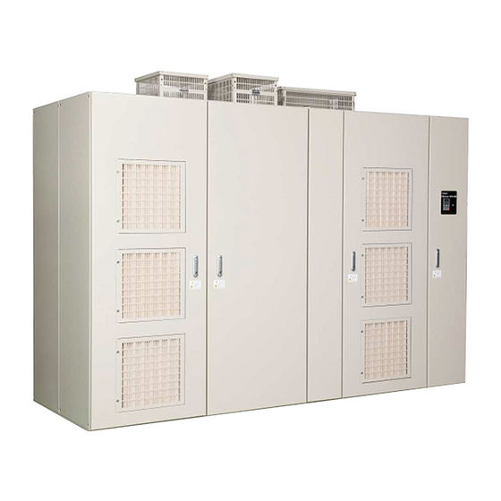
Super Energy-Saving Medium-Voltage AC Drive
FSDrive-MV1000
Instructions
Class: 2 kV, 3 kV, 4 kV, 6 kV, and 11 kV
To properly use the product, read this manual thoroughly and retain
for easy reference, inspection, and maintenance. Ensure the end user
receives this manual.
MANUAL NO. TOEP C710687 02B
1
4
Receiving
5
2
Mechanical Installation
6
3
Electrical Installation
Start-Up Programming &
7
4
Operation
5
8
Troubleshooting
Periodic Inspection &
A
6
Maintenance
B
7
Options
A
C
Specifications
B
D
Standards Compliance
MEMOBUS/Modbus
C
E
Communications
Advertisement
Table of Contents
Troubleshooting

Related Manuals for YASKAWA FSDrive-MV1000 Series


Summary of Contents for YASKAWA FSDrive-MV1000 Series
- Page 1 Super Energy-Saving Medium-Voltage AC Drive FSDrive-MV1000 Instructions Class: 2 kV, 3 kV, 4 kV, 6 kV, and 11 kV To properly use the product, read this manual thoroughly and retain for easy reference, inspection, and maintenance. Ensure the end user receives this manual.
- Page 2 Yaskawa. No patent liability is assumed with respect to the use of the information contained herein. Moreover, because Yaskawa is constantly striving to improve its high-quality products, the information contained in this manual is subject to change without notice.
-
Page 3: Table Of Contents
Control Panel ............36 YASKAWA ELECTRIC TOEP C710687 02B FSDrive-MV1000 Instructions... - Page 4 Setup Group Parameters..........119 YASKAWA ELECTRIC TOEP C710687 02B FSDrive-MV1000 Instructions...
- Page 5 Fault Reset Methods..........182 YASKAWA ELECTRIC TOEP C710687 02B FSDrive-MV1000 Instructions...
- Page 6 A.2 Drive Specifications ..........218 YASKAWA ELECTRIC TOEP C710687 02B FSDrive-MV1000 Instructions...
- Page 7 Slave Not Responding ..........253 Index ..........................254 Revision History ......................259 YASKAWA ELECTRIC TOEP C710687 02B FSDrive-MV1000 Instructions...
- Page 8 YASKAWA ELECTRIC TOEP C710687 02B FSDrive-MV1000 Instructions...
-
Page 9: Preface And General Safety
Preface and General Safety This section provides safety messages pertinent to this product that, if not heeded, may result in fatality, personal injury, or equipment damage. Yaskawa is not responsible for the consequences of ignoring these instructions. PREFACE ............10 GENERAL SAFETY . -
Page 10: Preface
Note: Indicates a supplement or precaution that does not cause drive damage. Indicates a term or definition used in this manual. TERMS TERMS TERMS u Terms and Abbreviations • Drive, MV1000: Yaskawa FSDrive-MV1000 Series MV1000 TERMS TERMS TERMS • V/f: V/f Control • OLV: Open Loop Vector Control •... -
Page 11: General Safety
• When ordering a new copy of the manual due to damage or loss, contact your Yaskawa representative or the nearest Yaskawa sales office and provide the manual number shown on the front cover. -
Page 12: Safety Messages
Never modify the drive. Failure to comply could result in serious injury or death. Yaskawa is not responsible for the consequences of any modification of the product by the user or any client of the user. Do not allow unqualified personnel to perform work on the drive. - Page 13 Do not connect or operate any equipment with visible damage or missing parts. Also check the cable wiring and selection of peripheral devices to identify the cause. Contact your Yaskawa representative or the nearest Yaskawa sales office before restarting the drive or the peripheral devices if the cause cannot be identified.
-
Page 14: Drive Label Warning Example
Serial number nameplate Warning information nameplate A Figure i.1 Class: 2 kV Class: 3 kV Figure i.2 Asia Serial number nameplate Warning information nameplate A Warning information nameplate B Figure i.2 Class: 3 kV YASKAWA ELECTRIC TOEP C710687 02B FSDrive-MV1000 Instructions... - Page 15 Class: 11 kV Figure i.5 Asia Warning information Warning information Danger information Nameplate C Nameplate C Nameplate C Serial number nameplate Danger information nameplate A Warning information nameplate B Figure i.5 Class: 11 kV YASKAWA ELECTRIC TOEP C710687 02B FSDrive-MV1000 Instructions...
- Page 16 Figure i.7 Warning Information Example Nameplate B Nameplate C Figure i.8 Asia Figure i.8 Danger Information Example Nameplate C Note: This danger information is not indicated on 2 kV and 4 kV class drives. YASKAWA ELECTRIC TOEP C710687 02B FSDrive-MV1000 Instructions...
-
Page 17: Mechanical Interlock
Figure i.9 Asia A – Medium voltage panel C – Medium voltage panel (Power Cells) (Transformer) B – Low voltage panel (Controller) Figure i.9 Specification of Interlock Key (Kirk Key type F-Flat mounted) YASKAWA ELECTRIC TOEP C710687 02B FSDrive-MV1000 Instructions... -
Page 18: Notes On Using Drives
Refer to Storing Spare Parts on page 208 for details. Compliance with Local Laws Please comply with the law of the relevant country where the drive panel is installed. For details, contact your Yaskawa representative. YASKAWA ELECTRIC TOEP C710687 02B FSDrive-MV1000 Instructions... -
Page 19: Settings
Hoisting Some large capacity drives require that the transformer, not the transformer panel, be hoisted directly. Hoisting the drive panel may damage the drive. Refer to Drive Transportation on page 44 for details. YASKAWA ELECTRIC TOEP C710687 02B FSDrive-MV1000 Instructions... - Page 20 (It is advisable to separate them by a distance of 30 cm or more.) Leakage Current Harmonic leakage current passes through stray capacitance between the drive power lines, ground and the motor lines. Consider taking measures against this leakage current. YASKAWA ELECTRIC TOEP C710687 02B FSDrive-MV1000 Instructions...
-
Page 21: Notes On Motor Operation
Subsynchronous resonance can occur with long motor shafts and in applications such as turbines, blowers, and fans with high inertia loads. Use Closed Loop Vector Control when these applications experience mechanical resonance problems. YASKAWA ELECTRIC TOEP C710687 02B FSDrive-MV1000 Instructions... -
Page 22: Warranty Information
Repairs If a Yaskawa product is found to be defective due to Yaskawa workmanship or materials and the defect occurs during the warranty period, Yaskawa will bear the cost of repairing the unit. However, if the Yaskawa Authorized Service Center determines that the problem with a Yaskawa product is not due to defects in Yaskawa’s workmanship or materials, then... -
Page 23: Receiving
MODEL NUMBER AND NAMEPLATE CHECK......29 COMPONENT NAMES AND CONFIGURATIONS......31 YASKAWA ELECTRIC TOEP C710687 02B FSDrive-MV1000 Instructions... -
Page 24: Section Safety
W ARNING Electrical Shock Hazard If any parts in the drive are damaged or missing, stop the drive and contact your Yaskawa representative or the nearest Yaskawa sales office. Electrical circuits could fail when current is applied, resulting in death, serious injury, or fire. -
Page 25: General Description
2300 A A 550 <1> A A 600 2750 2500 <1> <1> Under development <2> Indicates the power of Yaskawa’s 4-pole motors. Class: 3 kV Table 1.2 MV1000 Models (Class: 3 kV) Power Input Output Rated Output Max. Applicable Supply... - Page 26 D D 575 4500 4140 <1> D D 625 5000 4500 <1> <1> Under development <2> Indicates the power of Yaskawa’s 4-pole motors. Class: 6 kV Table 1.4 MV1000 Models (Class: 6 kV) Power Input Output Rated Output Max. Applicable Supply...
- Page 27 H H 330 <1> H H 400 7600 6100 <1> 9900 7930 H H 520 <1> H H 650 12000 9910 <1> <1> Under development <2> Indicates the capacities of Yaskawa’s 4-pole motors. YASKAWA ELECTRIC TOEP C710687 02B FSDrive-MV1000 Instructions...
-
Page 28: Control Mode Selection
Set L7-07 = 1 (integral control) in cases where a torque limit has been enabled during accel/decel (for use in winding machines, etc.). YASKAWA ELECTRIC TOEP C710687 02B FSDrive-MV1000 Instructions... -
Page 29: Model Number And Nameplate Check
DANGER! If any parts in the drive are damaged or missing, stop the drive and contact your Yaskawa representative or the nearest Yaskawa sales office. Electrical circuits could fail when current is applied, resulting in death, serious injury, or fire. -
Page 30: Drive Model Number Definition
375 A 550 A 440 A 600 A 505 A 575 A 625 A Figure 1.2 Drive Model Number Definition Note: All input voltages are not necessarily compatible with all output voltage classes. YASKAWA ELECTRIC TOEP C710687 02B FSDrive-MV1000 Instructions... -
Page 31: Component Names And Configurations
Figure 1.4 Internal Layout (Drive: 2 kV class, 600 HP) Figure 1.5 Asia Power Cell panel Transformer panel Control panel A – Digital Operator Figure 1.5 External Appearance, Viewing Doors (Drive: 3 kV Class, 800 kVA) YASKAWA ELECTRIC TOEP C710687 02B FSDrive-MV1000 Instructions... - Page 32 A – Cooling fans D – Main circuit output terminals B – Power Cells E – Main circuit input terminals C – Control circuit terminal Figure 1.8 Internal Layout (Drive: 4 kV Class, 1000 HP) YASKAWA ELECTRIC TOEP C710687 02B FSDrive-MV1000 Instructions...
- Page 33 Figure 1.10 Internal Layout (Drive: 6 kV Class, 1600 kVA) Figure 1.11 Asia Transformer panel Power Cell Control panel panel A – Digital Operator Figure 1.11 External Appearance, Viewing Doors (Drive: 11 kV Class, 2650 kVA) YASKAWA ELECTRIC TOEP C710687 02B FSDrive-MV1000 Instructions...
- Page 34 A – Cooling fans D – Main circuit input terminals B – Power Cells E – Main circuit output terminals C – Control circuit terminal Figure 1.12 Internal Layout (Drive: 11 kV Class, 2650 kVA) YASKAWA ELECTRIC TOEP C710687 02B FSDrive-MV1000 Instructions...
-
Page 35: Digital Operator, Communications Connector, And Internal Layout For Control Panel
Note: A digital operator for reading and writing parameter settings and monitoring status and faults, and a USB connector for DriveWizard Plus MV communications are provided on the control panel door. Refer to Using the Digital Operator on page 109 for details on the names and functions of the digital operator controls. YASKAWA ELECTRIC TOEP C710687 02B FSDrive-MV1000 Instructions... -
Page 36: Transformer Panel
• Peripheral circuits such as an isolation amplifier for analog I/O • Control terminals Note: A Single-phase, 200/220-Vac power supply is required as the power source for the cooling fan and control circuit. YASKAWA ELECTRIC TOEP C710687 02B FSDrive-MV1000 Instructions... - Page 37 Refer to Spare Parts on page 207 for the power supply model. • 5 V: Control circuit power supply • ± 15 V: Analog I/O power supply • 24 V: Contact I/O power supply YASKAWA ELECTRIC TOEP C710687 02B FSDrive-MV1000 Instructions...
- Page 38 1.4 Component Names and Configurations YASKAWA ELECTRIC TOEP C710687 02B FSDrive-MV1000 Instructions...
-
Page 39: Mechanical Installation
STORING DRIVES ..........71 YASKAWA ELECTRIC TOEP C710687 02B FSDrive-MV1000 Instructions... -
Page 40: Section Safety
40°C and a humidity of no greater than 85% (Yaskawa recommends the installation of an air conditioner). Observe the following precautions when installing the drive panel. - Page 41 An incorrect storage method could result in damage to, or failure of, the drive. Before turning on the power to the drive after a long period in storage, carefully check for moisture and dust. Failure to comply could result in damage by fire or other damage. YASKAWA ELECTRIC TOEP C710687 02B FSDrive-MV1000 Instructions...
-
Page 42: Mechanical Installation
40°C and a humidity of no greater than 85% (Yaskawa recommends the installation of an air conditioner). -
Page 43: Installation Space
Note: If the installation space for the drive is restricted and the space indicated in the figures below cannot be secured, contact your Yaskawa representatives or the nearest Yaskawa sales office. Figure 2.1... -
Page 44: Drive Transportation
2 kV class: 200 to 600 HP, 700 to 1750 HP, and 2000 to 2750 HP 4 kV class: 1750 to 3000 HP, 3500 to 5000 HP 11 kV class: 5000 to 12000 kVA YASKAWA ELECTRIC TOEP C710687 02B FSDrive-MV1000 Instructions... - Page 45 1. Attach the wire ropes for lifting to the support hooks on the top of the panel to lift the drive. Figure 2.2 Wire ropes for lifting Hanging angle of 45°±15° Top view Drive Front view Figure 2.2 Inserting Wire Ropes for Lifting 2. Ensure that the hanging angle is 45°±15°. YASKAWA ELECTRIC TOEP C710687 02B FSDrive-MV1000 Instructions...
- Page 46 DANGER! When lifting the transformer panel, take care to ensure that the housing is not damaged by contact with the ceiling plate or other parts. Failure to comply could result in deformation of the transformer panel or damage to the ceiling plate. YASKAWA ELECTRIC TOEP C710687 02B FSDrive-MV1000 Instructions...
- Page 47 Top view Pass the wire rope through the support hook while lifting it. Drive Front view Figure 2.5 Inserting Wire Ropes for Lifting 2. Ensure that the hanging angle is 45° 15°. ± YASKAWA ELECTRIC TOEP C710687 02B FSDrive-MV1000 Instructions...
- Page 48 DANGER! When lifting the transformer panel, take care to ensure that the housing is not damaged by contact with the ceiling plate or other parts. Failure to comply could result in deformation of the transformer panel or damage to the ceiling plate. YASKAWA ELECTRIC TOEP C710687 02B FSDrive-MV1000 Instructions...
- Page 49 DANGER! When lifting the transformer panel, take care to ensure that the housing is not damaged by contact with the ceiling plate or other parts. Failure to comply could result in deformation of the transformer panel or damage to the ceiling plate. YASKAWA ELECTRIC TOEP C710687 02B FSDrive-MV1000 Instructions...
- Page 50 1. Attach the wire ropes for lifting to the support hooks on the top of the panel to lift the drive. Figure 2.10 Wire ropes for lifting Hanging angle of 45°±15° Top view Drive Front view Figure 2.10 Inserting Wire Ropes for Lifting 2. Ensure that the hanging angle is 45°±15°. YASKAWA ELECTRIC TOEP C710687 02B FSDrive-MV1000 Instructions...
- Page 51 DANGER! When lifting the transformer panel, take care to ensure that the housing is not damaged by contact with the ceiling plate or other parts. Failure to comply could result in deformation of the transformer panel or damage to the ceiling plate. YASKAWA ELECTRIC TOEP C710687 02B FSDrive-MV1000 Instructions...
- Page 52 Top view Pass the wire rope through the support hook while lifting it. Drive Front view Figure 2.13 Inserting Wire Ropes for Lifting 2. Ensure that the hanging angle is 45°±15°. YASKAWA ELECTRIC TOEP C710687 02B FSDrive-MV1000 Instructions...
- Page 53 DANGER! When lifting the transformer panel, take care to ensure that the housing is not damaged by contact with the ceiling plate or other parts. Failure to comply could result in deformation of the transformer panel or damage to the ceiling plate. YASKAWA ELECTRIC TOEP C710687 02B FSDrive-MV1000 Instructions...
- Page 54 DANGER! When lifting the transformer panel, take care to ensure that the housing is not damaged by contact with the ceiling plate or other parts. Failure to comply could result in deformation of the transformer panel or damage to the ceiling plate. YASKAWA ELECTRIC TOEP C710687 02B FSDrive-MV1000 Instructions...
- Page 55 1. Attach the wire ropes for lifting to the support hooks on the top of the panel to lift the drive. Figure 2.18 Hanging angle of 45°±15° Wire ropes for lifting Top view Drive Front view Figure 2.18 Inserting Wire Ropes for Lifting 2. Ensure that the hanging angle is 45°±15°. YASKAWA ELECTRIC TOEP C710687 02B FSDrive-MV1000 Instructions...
- Page 56 DANGER! When lifting the transformer panel, take care to ensure that the housing is not damaged by contact with the ceiling plate or other parts. Failure to comply could result in deformation of the transformer panel or damage to the ceiling plate. YASKAWA ELECTRIC TOEP C710687 02B FSDrive-MV1000 Instructions...
-
Page 57: Side-By-Side Installation
NOTICE: When bolting frames between panel to each other, make secure connections by using the tightening torque indicated in this manual. Any space between two frames may cause a leakage of cooling air, resulting in drive failure. YASKAWA ELECTRIC TOEP C710687 02B FSDrive-MV1000 Instructions... -
Page 58: Installing Cooling Exhaust Covers
12-φ17 C C 330 <2> C C 400 1130 – – – 1530 12-φ17 <2> C C 520 – – 1530 18-φ17 <2> Figure 2.28 C C 650 – – 1530 18-φ17 <2> YASKAWA ELECTRIC TOEP C710687 02B FSDrive-MV1000 Instructions... - Page 59 1120 – – 1730 32-φ17 <1> <2> Figure 2.42 407.5 1120 – – – 1730 34-φ17 H H 650 <1> <2> <1> Under development <2> Side-by-side configurations comprising two or more drive panels YASKAWA ELECTRIC TOEP C710687 02B FSDrive-MV1000 Instructions...
- Page 60 Figure 2.23 Dimension Drawing 1 for Bottom (Class: 2 kV) Figure 2.24 12-φ17 Asia Cable inlet Front: With the door removed Unit: mm Figure 2.24 Dimension Drawing 2 for Bottom (Class: 2 kV) YASKAWA ELECTRIC TOEP C710687 02B FSDrive-MV1000 Instructions...
- Page 61 Figure 2.26 Dimension Drawing 2 for Bottom (Class: 3 kV) Figure 2.27 12-φ17 Asia Cable inlet Unit: mm Front: With the door removed Figure 2.27 Dimension Drawing 3 for Bottom (Class: 3 kV) YASKAWA ELECTRIC TOEP C710687 02B FSDrive-MV1000 Instructions...
- Page 62 Figure 2.29 Dimension Drawing 1 for Bottom (Class: 4 kV) Figure 2.30 12-φ17 Asia Cable inlet Front: With the door removed Unit: mm Figure 2.30 Dimension Drawing 2 for Bottom (Class: 4 kV) YASKAWA ELECTRIC TOEP C710687 02B FSDrive-MV1000 Instructions...
- Page 63 Figure 2.33 Dimension Drawing 3 for Bottom (Class: 6 kV) Figure 2.34 20-φ17 Asia Cable inlet Unit: mm Front: With the door removed Figure 2.34 Dimension Drawing 4 for Bottom (Class: 6 kV) YASKAWA ELECTRIC TOEP C710687 02B FSDrive-MV1000 Instructions...
- Page 64 Figure 2.37 Dimension Drawing 1 for Bottom (Class: 11 kV) Figure 2.38 14-φ17 Asia Cable inlet Unit: mm Front: With the door removed Figure 2.38 Dimension Drawing 2 for Bottom (Class: 11 kV) YASKAWA ELECTRIC TOEP C710687 02B FSDrive-MV1000 Instructions...
- Page 65 Figure 2.41 Dimension Drawing 5 for Bottom (Class: 11 kV) Figure 2.42 34-φ17 Asia Cable inlet W1 W1 W1 W1 W1 W1 Unit: mm Front: With the door removed Figure 2.42 Dimension Drawing 6 for Bottom (Class: 11 kV) YASKAWA ELECTRIC TOEP C710687 02B FSDrive-MV1000 Instructions...
-
Page 66: Dimensions
2550 2150 6900 <2> Figure 2.46 C C 400 4100 1600 2550 2150 6900 <2> C C 520 5300 1600 2800 2400 8100 <2> C C 650 5600 1600 2800 2400 8200 <2> YASKAWA ELECTRIC TOEP C710687 02B FSDrive-MV1000 Instructions... - Page 67 <1> Under development <2> Side-by-side configurations comprising two or more drive panels <3> The dimensions and masses are subject to change. For details on the CE-marking-conforming products, refer to European Standards on page 220. YASKAWA ELECTRIC TOEP C710687 02B FSDrive-MV1000 Instructions...
- Page 68 Figure 2.44 Max. 850 mm Asia Door opening dimension Figure 2.44 Dimension Drawing 2 (Class: 2 kV) Figure 2.45 Asia Max. 800 mm Door opening dimension Figure 2.45 Dimension Drawing 1 (Class: 3 kV) YASKAWA ELECTRIC TOEP C710687 02B FSDrive-MV1000 Instructions...
- Page 69 Figure 2.47 Asia Max. 800 mm Door opening dimension Figure 2.47 Dimension Drawing 1 (Class: 4 kV) Figure 2.48 Asia Max. 850 mm Door opening dimension Figure 2.48 Dimension Drawing 2 (Class: 4 kV) YASKAWA ELECTRIC TOEP C710687 02B FSDrive-MV1000 Instructions...
- Page 70 2.3 Dimensions Figure 2.49 Asia Max. 800 mm Door opening dimension Figure 2.49 Dimension Drawing (Class: 6 kV) Figure 2.50 Asia Max. 800 mm Door opening dimension Figure 2.50 Dimension Drawing (Class: 11 kV) YASKAWA ELECTRIC TOEP C710687 02B FSDrive-MV1000 Instructions...
-
Page 71: Storing Drives
Time Frame Storage of more than one month after unpacking or more than three months after shipping. Note: Contact your Yaskawa representative or the nearest Yaskawa sales office in advance if long-term storage is required. Surrounding Environment Secure a storage environment that satisfies the conditions cited for the drive’s installation environment. (refer to Installation Environment on page 42.) - Page 72 NOTICE: Before turning on the power to the drive after a long period in storage, carefully check for moisture and dust. Failure to comply could result in damage by fire or other damage. YASKAWA ELECTRIC TOEP C710687 02B FSDrive-MV1000 Instructions...
-
Page 73: Electrical Installation
WIRING CHECK ..........105 YASKAWA ELECTRIC TOEP C710687 02B FSDrive-MV1000 Instructions... -
Page 74: Section Safety
Improper equipment grounding could cause leakage current to flow to the drive. If so, the potential of the drive’s ground terminals becomes unstable at some distance from the grounding point, resulting in serious injury or death. YASKAWA ELECTRIC TOEP C710687 02B FSDrive-MV1000 Instructions... - Page 75 Do not attempt to modify or alter the drive. Yaskawa is not responsible for any modification of the drive made by the user. Check all the wiring and ensure that all connections are correct after installing the drive and connecting other devices.
- Page 76 Insulate the shielded wires of the drive, e.g. with tape, to prevent their contact with other signal lines or devices. Failure to comply could result in drive or equipment malfunction due to short circuit. YASKAWA ELECTRIC TOEP C710687 02B FSDrive-MV1000 Instructions...
-
Page 77: Standard Connection Diagram
NOTICE: Consider voltage tolerance levels and insulation in applications with a high input voltage or particularly long wiring distances. Contact your Yaskawa representative or the nearest Yaskawa sales office. u Class: 2 kV Figure 3.1... -
Page 78: Class: 3 Kv
Complementary PG output PG board (option) Phase-B signal 12 V ±5%, max. 200 mA Ground Relay board Phases-A/B/Z input Digital output: 8 points (option) Figure 3.2 Drive Standard Connection Diagram (Example: CIMR-MV2 C CA035) YASKAWA ELECTRIC TOEP C710687 02B FSDrive-MV1000 Instructions... -
Page 79: Class: 4 Kv
PG Complementary PG board (option) Phase-B signal 12 V ±5%, max. 200 mA Ground Relay board Phases-A/B/Z input Digital output: 8 points (option) Figure 3.3 Drive Standard Connection Diagram (Example: CIMR-MV2 D DA052) YASKAWA ELECTRIC TOEP C710687 02B FSDrive-MV1000 Instructions... -
Page 80: Class: 6 Kv
PG Complementary PG board (option) Phase-B signal 12 V ±5%, max. 200 mA Ground Relay Phases-A/B/Z input board Digital output: 8 points (option) Figure 3.4 Drive Standard Connection Diagram (Example: CIMR-MV2 F FA035) YASKAWA ELECTRIC TOEP C710687 02B FSDrive-MV1000 Instructions... -
Page 81: Class: 11 Kv
PG Complementary PG board (option) Phase-B signal 12 V ±5%, max. 200 mA Ground Relay Phases-A/B/Z input board Digital output: 8 points (option) Figure 3.5 Drive Standard Connection Diagram (Example: CIMR-MV2 H HA035) YASKAWA ELECTRIC TOEP C710687 02B FSDrive-MV1000 Instructions... -
Page 82: Terminals
E – Grounding terminal EA C – Control circuit terminals F – Main circuit input terminals R, S, and T Grounding terminal ED Figure 3.7 Terminal Locations (Drive: 3 kV Class, 800 kVA) YASKAWA ELECTRIC TOEP C710687 02B FSDrive-MV1000 Instructions... - Page 83 E – Grounding terminal EA C – Control circuit terminals F – Main circuit input terminals R, S, and T Grounding terminal ED Figure 3.9 Terminal Locations (Drive: 6 kV Class, 1600 kVA) YASKAWA ELECTRIC TOEP C710687 02B FSDrive-MV1000 Instructions...
- Page 84 E – Grounding terminal EA C – Control circuit terminals F – Main circuit input terminals R, S, and T Grounding terminal ED Figure 3.10 Terminal Locations (Drive: 11 kV Class, 2650 kVA) YASKAWA ELECTRIC TOEP C710687 02B FSDrive-MV1000 Instructions...
-
Page 85: Cable Routing
D – Main circuit output terminals I – Main circuit input terminals R, S, and T U, V, and W E – Cable bracket clamp Figure 3.11 Cable Routing (Drive: 2 kV Class, 700 HP) YASKAWA ELECTRIC TOEP C710687 02B FSDrive-MV1000 Instructions... - Page 86 D – Main circuit output terminals I – Main circuit input terminals R, S, and T U, V, and W E – Cable bracket clamp Figure 3.13 Cable Routing (Drive: 4 kV Class, 1250 HP) YASKAWA ELECTRIC TOEP C710687 02B FSDrive-MV1000 Instructions...
- Page 87 G – Input side main circuit cable D – Output side main circuit cable H – Input side main circuit terminals R, S, and T Figure 3.15 Cable Routing (Drive: 11 kV Class, 2650 kVA) YASKAWA ELECTRIC TOEP C710687 02B FSDrive-MV1000 Instructions...
-
Page 88: Cable Routing Precautions
Figure 3.16 A – Bracket grounding terminal B – Completely seal the external cable inlet port with fire-resistant putty so no open space remains Figure 3.16 External Cable Inlet Port YASKAWA ELECTRIC TOEP C710687 02B FSDrive-MV1000 Instructions... - Page 89 D – Pit cover (plugs any opening) J – Bracket ground E – Panel support base K – Shield ground F – Cable L – Cable terminal control Figure 3.17 Area Around the Drive Channel Base and Pit Cover YASKAWA ELECTRIC TOEP C710687 02B FSDrive-MV1000 Instructions...
-
Page 90: Main Circuit Wiring
Use high-voltage cables and ground any shielded cables. Separate cables for control from high-current circuits (main circuit and relay sequence circuits) to avoid induction from peripheral devices. (It is advisable to separate them by a distance of 30 cm or more.) YASKAWA ELECTRIC TOEP C710687 02B FSDrive-MV1000 Instructions... -
Page 91: Wire Gauges And Tightening Torques
31.5 to 39.5 150 to 325 <1> Ground 31.5 to 39.5 60 to 200 R, S, T, U, V, W 31.5 to 39.5 150 to 325 <1> Ground 31.5 to 39.5 60 to 200 YASKAWA ELECTRIC TOEP C710687 02B FSDrive-MV1000 Instructions... - Page 92 150 to 325 <1> Ground 78.5 to 98.0 150 to 325 R, S, T, U, V, W 78.5 to 98.0 150 to 325 <1> Ground 78.5 to 98.0 150 to 325 <1> Under development YASKAWA ELECTRIC TOEP C710687 02B FSDrive-MV1000 Instructions...
- Page 93 R, S, T, U, V, W 78.5 to 98.0 150 to 325 Ground 78.5 to 98.0 150 to 325 R, S, T, U, V, W 78.5 to 98.0 150 to 325 Ground 78.5 to 98.0 150 to 325 YASKAWA ELECTRIC TOEP C710687 02B FSDrive-MV1000 Instructions...
- Page 94 31.5 to 39.5 150 to 325 <1> Ground 31.5 to 39.5 60 to 200 R, S, T, U, V, W 31.5 to 39.5 150 to 325 <1> Ground 31.5 to 39.5 60 to 200 YASKAWA ELECTRIC TOEP C710687 02B FSDrive-MV1000 Instructions...
- Page 95 150 to 325 <1> Ground 78.5 to 98.0 150 to 325 R, S, T, U, V, W 78.5 to 98.0 150 to 325 <1> Ground 78.5 to 98.0 150 to 325 <1> Under development YASKAWA ELECTRIC TOEP C710687 02B FSDrive-MV1000 Instructions...
- Page 96 R, S, T, U, V, W 78.5 to 98.0 150 to 325 Ground 78.5 to 98.0 150 to 325 R, S, T, U, V, W 78.5 to 98.0 150 to 325 Ground 78.5 to 98.0 150 to 325 YASKAWA ELECTRIC TOEP C710687 02B FSDrive-MV1000 Instructions...
- Page 97 150 to 325 <1> Ground 78.5 to 98.0 150 to 325 R, S, T, U, V, W 78.5 to 98.0 150 to 325 <1> Ground 78.5 to 98.0 150 to 325 <1> Under development YASKAWA ELECTRIC TOEP C710687 02B FSDrive-MV1000 Instructions...
-
Page 98: Main Circuit Terminal And Motor Wiring
U, V and W. When using a motor with a PG, also switch phases-A and -B output signals, using the cable wire specified by Yaskawa when connecting the drive and the PG circuit. Refer to Motor Rotates in the Opposite Direction from the Run Command on page 185 for details. -
Page 99: Control Circuit Wiring
Contact input External fault reset ON: Reset Contact input Single-phase, 220 Vac/8 mA terminals − − Reserved ON: Run Contact input Run command/Stop command Single-phase, 220 Vac/8 mA OFF: Stop − − Reserved YASKAWA ELECTRIC TOEP C710687 02B FSDrive-MV1000 Instructions... - Page 100 <1> When a PG interface options is installed, only one type, either a line driver PG interface or a complementary type PG interface may be chosen for use. Note: Depending on parameter settings, either one or two boards can be inserted. In this table, it is assumed that one board is inserted. YASKAWA ELECTRIC TOEP C710687 02B FSDrive-MV1000 Instructions...
-
Page 101: Control Circuit Terminal Layout And Specifications
Shielded twisted-pair wire <2> <1> Terminals for 18 to 21 Insulated vinyl sheathed cable (CVV) for monitor of motor M3.5 0.8 to 1.0 0.5 to 2 1.25 <2> L26 to L37 control circuit windings YASKAWA ELECTRIC TOEP C710687 02B FSDrive-MV1000 Instructions... -
Page 102: Wiring The Control Circuit Terminal
NOTICE: Insulate the shielded wires of the drive, e.g. with tape, to prevent their contact with other signal lines or devices. Failure to comply could result in drive or equipment malfunction due to short circuit. YASKAWA ELECTRIC TOEP C710687 02B FSDrive-MV1000 Instructions... -
Page 103: Connecting To A Pc
• USB2-EXA50 (ELECOM) • KB-USB-R205 (Sanwa Supply) After connecting the drive to a PC, Yaskawa DriveWizard Plus MV can be used to monitor drive performance and manage parameter settings. For details, refer to the instruction manual for DriveWizard Plus MV. -
Page 104: External Interlock
<2> Always allocate necessary signals for protecting the system as external interlock signals. Examples: Machine lubrication unit normal (N.O. contact) or emergency stop normal (N.O. contact). Figure 3.21 Interlock Circuit Example YASKAWA ELECTRIC TOEP C710687 02B FSDrive-MV1000 Instructions... -
Page 105: Wiring Check
• No foreign matter or unnecessary screws remain. • There are no loose screws. • No wire ends have contact with terminals to which they are not intended. • The terminal numbers and cable lead names match. YASKAWA ELECTRIC TOEP C710687 02B FSDrive-MV1000 Instructions... - Page 106 3.9 Wiring Check YASKAWA ELECTRIC TOEP C710687 02B FSDrive-MV1000 Instructions...
-
Page 107: Start-Up Programming & Operation
TEST RUN WITH LOAD CONNECTED ....... . 132 CHECKING AND SAVING PARAMETER DEFAULT VALUES....133 YASKAWA ELECTRIC TOEP C710687 02B FSDrive-MV1000 Instructions... -
Page 108: Section Safety
Make sure that there are no personnel around the drive, motor and machine before turning the main circuit power on. Also check that couplings with motors, shaft keys and machinery are properly protected. YASKAWA ELECTRIC TOEP C710687 02B FSDrive-MV1000 Instructions... -
Page 109: Using The Digital Operator
0. <2> The LO/RE key can only switch between LOCAL and REMOTE when the drive is stopped. To disable the key to prohibit switching between LOCAL and REMOTE, set parameter o2-01 to 0. YASKAWA ELECTRIC TOEP C710687 02B FSDrive-MV1000 Instructions... -
Page 110: Lcd Display
Pressing scrolls the cursor to the right. RESET Pressing resets the existing drive fault or error. <1> Displayed when in Frequency Reference Mode. <2> Displayed when in Frequency Reference Mode and Monitor Mode. YASKAWA ELECTRIC TOEP C710687 02B FSDrive-MV1000 Instructions... -
Page 111: Alarm (Alm) Led Displays
Run command is active. Examples <1> Refer to Figure 4.3 for the difference between “flashing” and “flashing quickly”. Figure 4.3 1 sec Flashing common_TMonly Flashing quickly Figure 4.3 RUN LED Status and Meaning YASKAWA ELECTRIC TOEP C710687 02B FSDrive-MV1000 Instructions... -
Page 112: Menu Structure For Digital Operator
<5> The frequency reference appears after the initial display which shows the product name. <6> The information that appears on the display will vary depending on the drive. Figure 4.5 Digital Operator Menu and Screen Structure YASKAWA ELECTRIC TOEP C710687 02B FSDrive-MV1000 Instructions... -
Page 113: The Drive And Programming Modes
HELP DATA - MODE - Quick Setting Setup Group HELP DATA Programming Mode (Parameter setting) - MODE - Programming Parameter Setting Mode HELP DATA - MODE - Auto-Tuning Auto-Tuning Mode AUTO HELP DATA YASKAWA ELECTRIC TOEP C710687 02B FSDrive-MV1000 Instructions... -
Page 114: Navigating The Drive And Programming Modes
Motor parameters are calculated and set automatically. - MODE - Auto-Tuning Refer to Auto-Tuning on page 124 for details. AUTO HELP DATA Frequency Reference Drive Mode Returns to the frequency reference display screen. YASKAWA ELECTRIC TOEP C710687 02B FSDrive-MV1000 Instructions... - Page 115 Simplified Setup Using the Setup Group on page 116 for details.) • Parameter Setting Mode: Access and edit all parameter settings • Auto-Tuning Mode: Automatically calculates and sets motor parameters to optimize drive performance YASKAWA ELECTRIC TOEP C710687 02B FSDrive-MV1000 Instructions...
- Page 116 To confirm the parameter list displayed in the Setup Group, go to the steps below. <2> To go back to the initial screen, press To edit another parameter in the Setup Group, press Figure 4.7 Setup Group Example YASKAWA ELECTRIC TOEP C710687 02B FSDrive-MV1000 Instructions...
-
Page 117: Changing Parameter Settings Or Values
(0.0~6000.0) “60.0sec” Home DATA Press until C1-01 is displayed. - VERIFY - PRG Accel Time 1 Press the key to access the setting value. Left digit flashes. C1-01=0020.0sec (0.0~6000.0) “60.0sec” Home DATA YASKAWA ELECTRIC TOEP C710687 02B FSDrive-MV1000 Instructions... -
Page 118: Switching Between Local And Remote
It is possible to switch between LOCAL and REMOTE modes using one of the contact input terminals H1-01 to H1-16 (set the corresponding parameter H1- to 1). Note: Setting H1- to 1 disables the LO/RE key on the digital operator. YASKAWA ELECTRIC TOEP C710687 02B FSDrive-MV1000 Instructions... -
Page 119: Setup Group Parameters
L3-04 Stall Prevention Selection during Deceleration E1-04 Maximum Output Frequency Note: Parameter availability depends on the control mode set in A1-02; some parameters listed above may not be accessible in all control modes. YASKAWA ELECTRIC TOEP C710687 02B FSDrive-MV1000 Instructions... -
Page 120: Start-Up Flowcharts
Flowchart A-2 From Flowchart A-1, A-2 Fine tune parameters. Adjust application settings if necessary. Check the machine operation and verify parameter settings. Drive is ready to run the application. Figure 4.8 Basic Start-Up YASKAWA ELECTRIC TOEP C710687 02B FSDrive-MV1000 Instructions... -
Page 121: Subchart A-1: Parallel Operation Of Multiple Motors By V/F Control
Verify external signal commands to the drive work as desired. Couple the load or machine to the motor. Run the machine and check for desired operation. Return to Flowchart Figure 4.9 Parallel Operation of Multiple Motors by V/f Control YASKAWA ELECTRIC TOEP C710687 02B FSDrive-MV1000 Instructions... -
Page 122: Subchart A-2: High Performance Operation Using Olv Or Clv
Verify external signal commands to the drive work as desired. Run the machine and check for desired operation. Return to Flowchart <1> Ensure that the brake is released. Figure 4.10 High Performance Operation Using OLV or CLV YASKAWA ELECTRIC TOEP C710687 02B FSDrive-MV1000 Instructions... -
Page 123: Powering Up The Drive
The data display area displays the frequency reference. Operation lights. The display content depends on the details of fault. Fault Refer to Troubleshooting on page 137 and take appropriate measures. (Example: Current detection fault) YASKAWA ELECTRIC TOEP C710687 02B FSDrive-MV1000 Instructions... -
Page 124: Auto-Tuning
T1-04 Motor Base Frequency T1-05 Number of Motor Pole T1-06 – Motor Base Speed T1-07 r/min PG Number of Pulses Per T1-08 <1> Revolution <1> Set when Closed Loop Vector control is selected. YASKAWA ELECTRIC TOEP C710687 02B FSDrive-MV1000 Instructions... -
Page 125: Before Auto-Tuning The Drive
Auto-Tuning Interruption and Fault Codes If tuning results are abnormal or is pressed before completion, Auto-Tuning will be interrupted and a fault code will appear on the digital operator. Figure 4.11 Figure 4.11 Auto-Tuning Aborted Display YASKAWA ELECTRIC TOEP C710687 02B FSDrive-MV1000 Instructions... -
Page 126: Auto-Tuning Operation Example
“20000kW” Press to save the setting. Entry Accepted - A.TUNE - Mtr Rated Power The display automatically returns to the display in Step 1. T1-02= 25000kW (0 ~ 65000) “20000kW” DATA YASKAWA ELECTRIC TOEP C710687 02B FSDrive-MV1000 Instructions... -
Page 127: Parameter Settings During Auto-Tuning For Induction Motors
Selects the motor to be tuned when motor 1/2 switching is enabled (i.e., a digital input is set for function H1- = 16). This parameter is not displayed if motor 1/2 switching is disabled. Name Setting Range Default T1-00 Motor 1/Motor 2 Selection 1 or 2 YASKAWA ELECTRIC TOEP C710687 02B FSDrive-MV1000 Instructions... - Page 128 E1-04 (E3-04 for motor 2) after Auto-Tuning is complete. Name Setting Range Default T1-05 Motor Base Frequency 0.0 to 120.0 Hz 60.0 Hz YASKAWA ELECTRIC TOEP C710687 02B FSDrive-MV1000 Instructions...
- Page 129 Sets the number of pulses from the PG encoder. Set the actual number of pulses for one full motor rotation. T1-08 will only be displayed in CLV. Name Setting Range Default T1-08 PG Number of Pulses Per Revolution 0 to 60000 ppr 600 ppr YASKAWA ELECTRIC TOEP C710687 02B FSDrive-MV1000 Instructions...
-
Page 130: No-Load Operation Test Run
The current should be well below the motor rated current. Example: 6 Hz → 60 Hz After checking drive output current, reduce the frequency reference to 0.0 Hz by – pressing the button. The motor will decelerate. YASKAWA ELECTRIC TOEP C710687 02B FSDrive-MV1000 Instructions... - Page 131 4.7 No-Load Operation Test Run Operating Procedure LCD Display After the motor slows to a stop, press to stop running. RUN flashes until the motor comes to a complete stop. YASKAWA ELECTRIC TOEP C710687 02B FSDrive-MV1000 Instructions...
-
Page 132: Test Run With Load Connected
• If the application permits running the load in the reverse direction, change the motor direction and the frequency reference while watching for abnormal motor oscillation or vibration. • Correct any problems that occur with hunting, oscillation, or other control-related issues. YASKAWA ELECTRIC TOEP C710687 02B FSDrive-MV1000 Instructions... -
Page 133: Checking And Saving Parameter Default Values
0 to 2 (Only the parameters A2-01 to A2-16 for each application and the recently changed parameters A2-17 to A2-32 can be set and monitored.) 2: Advanced Access (Can set and monitor all parameters) YASKAWA ELECTRIC TOEP C710687 02B FSDrive-MV1000 Instructions... -
Page 134: Password Settings: A1-04, A1-05
DriveWizard Plus MV is a PC software tool for parameter management, monitoring, and diagnosis. DriveWizard Plus MV can load, store, and copy parameter settings. For more information on the operating procedure, refer to the operation manual supplied with the DriveWizard Plus MV software. YASKAWA ELECTRIC TOEP C710687 02B FSDrive-MV1000 Instructions... - Page 135 READ INV→OP READING After the operation finishes, the screen automatically returns to the copy function selection screen. READ COMPLETE Press until the screen returns to the initial screen. Initial setting screen YASKAWA ELECTRIC TOEP C710687 02B FSDrive-MV1000 Instructions...
- Page 136 4.9 Checking and Saving Parameter Default Values YASKAWA ELECTRIC TOEP C710687 02B FSDrive-MV1000 Instructions...
-
Page 137: Troubleshooting
5.10 DIAGNOSING AND RESETTING FAULTS ......181 5.11 TROUBLESHOOTING WITHOUT FAULT DISPLAY..... . 183 YASKAWA ELECTRIC TOEP C710687 02B FSDrive-MV1000 Instructions... -
Page 138: Section Safety
Verify that the rated voltage of the drive matches the voltage of the incoming drive input power before applying power. Do not use improper combustible materials. Failure to comply could result in serious injury or death by fire. Attach the drive to metal or other noncombustible material. YASKAWA ELECTRIC TOEP C710687 02B FSDrive-MV1000 Instructions... - Page 139 Do not attempt to modify or alter the drive. Yaskawa is not responsible for any modification of the drive made by the user. Check all the wiring and ensure that all connections are correct after installing the drive and connecting other devices.
-
Page 140: Motor Performance Fine-Tuning
Refer to the section below that corresponds to the motor control method used. Note: This section describes parameters that are commonly edited and may be set incorrectly. Consult Yaskawa for more information on detailed settings and fine-tuning the drive. - Page 141 When using Open Loop Vector Control, leave the torque compensation gain (C4-01) at its default setting of 1.00. In the Open Loop Vector Control, when the speed precision is not improved for regenerative operation, enable slip compensation during regeneration by setting parameter C3-04 to 1. YASKAWA ELECTRIC TOEP C710687 02B FSDrive-MV1000 Instructions...
-
Page 142: Fine-Tuning Closed Loop Vector Control
• Ensure that the drive capacity is greater than the motor capacity when increasing this setting. Be careful L7-07, L7-16) when reducing this value because motor speed loss may occur with heavy loads. YASKAWA ELECTRIC TOEP C710687 02B FSDrive-MV1000 Instructions... -
Page 143: Types Of Faults, Alarms, And Errors
Check the digital operator for information about possible faults if the drive or motor fails to operate. Refer to Using the Digital Operator on page 109. If problems occur that are not covered in this manual, contact the nearest Yaskawa representative with the following information: • Drive model • Software version (U1-25, U1-26, U1-27, U1-28, U1-29, U9-09 , U9-10 <1>... -
Page 144: Fault, Alarm And Error Displays
CPF40 to CPF43 Option Card Error Occurred at oFC03 to oFC11 Option Port CN5-C Speed Deviation (for Control Mode with PG) Option Card Fault at Option Port oFC12 to oFC17 CN5-C Door Open YASKAWA ELECTRIC TOEP C710687 02B FSDrive-MV1000 Instructions... - Page 145 PG-X3 option) Forward/Reverse Run Motor Switch during Run Command Input Error Option Card External Fault MEMOBUS/Modbus Communication Test Mode External Fault (input Error terminal) EF16 Transformer Temperature Fan Fault TMA1 Fault YASKAWA ELECTRIC TOEP C710687 02B FSDrive-MV1000 Instructions...
- Page 146 Rated Slip Error End5 Resistance Tuning Error Er-09 Acceleration Error End7 No-Load Current Alarm Er-10 Motor Direction Error Er-01 Motor Data Error Er-11 Motor Speed Fault Er-02 Minor Fault Er-12 Current Detection Error YASKAWA ELECTRIC TOEP C710687 02B FSDrive-MV1000 Instructions...
- Page 147 Voltage Class, Capacity Mismatch Parameter settings in the drive and dFPS Drive Model Mismatch vFyE those saved to the copy function are not the same Comparing Parameter Settings Task Complete vrFy (flashing) iFEr Communication Error YASKAWA ELECTRIC TOEP C710687 02B FSDrive-MV1000 Instructions...
-
Page 148: Fault Detection
• Use only recommended cables or other shielded line. Ground the shield on the controller side or on the drive input power side. • Separate all communication wiring from drive power lines. Install an EMC noise filter to the drive input power supply. YASKAWA ELECTRIC TOEP C710687 02B FSDrive-MV1000 Instructions... - Page 149 • Replace the motor. One of the motor cables has short circuited or • Check the motor cable. there is a grounding problem. • Remove the short circuit. YASKAWA ELECTRIC TOEP C710687 02B FSDrive-MV1000 Instructions...
- Page 150 The Power Cell input voltage is incorrect. Correct the Power Cell input voltage. The Power Cell input power fuse has blown. Replace the Power Cell input power fuse. Cell control board fault Replace the cell control board. YASKAWA ELECTRIC TOEP C710687 02B FSDrive-MV1000 Instructions...
- Page 151 • Cycle control power to the drive. There is a self-diagnostic error in control circuit. • If the problem continues, replace the control board or the entire drive. Contact Yaskawa or a Yaskawa representative for instructions on replacing the control board.
- Page 152 External fault input at contact input terminal 10 External Fault (contact input 11) EF11 External fault input at contact input terminal 11 External Fault (contact input 12) EF12 External fault input at contact input terminal 12 YASKAWA ELECTRIC TOEP C710687 02B FSDrive-MV1000 Instructions...
- Page 153 • Cycle power to the drive. EEPROM. • If the problem continues, replace the control board or the entire drive. Contact Yaskawa or a Yaskawa representative for instructions on replacing the control board. If the problem continues, replace the control board or the entire drive. Contact Yaskawa or a Hardware problem.
- Page 154 Large stray capacitance of cable and terminal • Reduce the amount of stray capacitance. If the problem continues, replace the control board or the entire drive. Contact Yaskawa or a Hardware problem Yaskawa representative for instructions on replacing the control board.
- Page 155 • Cycle control power to the drive. Option card or hardware is damaged. • If the problem continues, replace the control board or the entire drive. Contact Yaskawa or a Yaskawa representative for instructions on replacing the control board. Digital Operator Display...
- Page 156 • Cycle control power to the drive. Option card or hardware is damaged. • If the problem continues, replace the control board or the entire drive. Contact Yaskawa or a Yaskawa representative for instructions on replacing the control board. Digital Operator Display...
- Page 157 Check the settings of parameters L6-02 and L6-03. load. Fault on the machine side (e.g., machine is • Check the status of the machine. locked up) • Remove the cause of the fault. YASKAWA ELECTRIC TOEP C710687 02B FSDrive-MV1000 Instructions...
- Page 158 Reduce the setting for C5-01 (ASR Proportional Gain 1) and increase the setting for C5-02 Overshoot is occurring. (ASR Integral Time 1). Check the setting for the overspeed detection level and the overspeed detection time (F1-08 and Inappropriate parameter settings F1-09). YASKAWA ELECTRIC TOEP C710687 02B FSDrive-MV1000 Instructions...
- Page 159 Check the parameter settings. If the problem occurs even at a low temperature, for example immediately after switching on the Thermistor fault and disconnected signal line power, contact Yaskawa or your nearest sales representative. Digital Operator Display Fault Name Transformer Temperature Fault 1 TME1 The temperature of the transformer has exceeded the temperature fault level.
- Page 160 Clean the intake filter. Overheated transformer and disconnected signal If the problem occurs at a low temperature, for example immediately after applying power, line contact Yaskawa or your nearest sales representative. Digital Operator Display Fault Name Transformer Temperature Sensor Disconnection TME3 Transformer temperature = -30°C or lower for 10 continuous seconds...
- Page 161 <1> When used for monitoring, AI-A3 and DI-A3 can be installed in any of CN5-A, B or C. <2> Use port CN5-C when connecting one PG option card. Use ports CN5-B and CN5-C when connecting two PG option cards. YASKAWA ELECTRIC TOEP C710687 02B FSDrive-MV1000 Instructions...
-
Page 162: Alarm Detection
• Perform an self-diagnostics check. • If the problem continues, replace either the control board or the entire Communications circuitry is damaged. drive. For instructions on replacing the control board, contact Yaskawa or your nearest sales representative. YASKAWA ELECTRIC TOEP C710687 02B FSDrive-MV1000 Instructions... - Page 163 Both forward run and reverse run closed simultaneously for over 0.5 s. Minor Fault Output Cause Possible Solutions Check the forward and reverse command sequence and correct the problem. Sequence error Note: When minor fault EF is detected, the motor ramps to stop. YASKAWA ELECTRIC TOEP C710687 02B FSDrive-MV1000 Instructions...
- Page 164 • Reconnect the signal line • Check if the unused terminals have been set for H1- = 2C to 2F The contact inputs are set incorrectly. (External Fault). • Change the terminal settings YASKAWA ELECTRIC TOEP C710687 02B FSDrive-MV1000 Instructions...
- Page 165 • Check whether an error is displayed while all the cooling fans are in operation. Fan fault detection board fault • Replace the fan fault detection board. Contact Yaskawa or your nearest sales representative on replacing the board. Digital Operator Display...
- Page 166 (b3-02 and b3-03 respectively). incorrectly. • After Auto-Tuning, set b3-24 to 1 to enable Speed Estimation Speed Search. Output current fluctuation due to power supply Check the power supply for phase loss. loss YASKAWA ELECTRIC TOEP C710687 02B FSDrive-MV1000 Instructions...
- Page 167 Digital Operator Display Minor Fault Name PG Hardware Fault (detected when using a PG-X3 option card) PGoH PG cable disconnection was detected. Minor Fault Output Cause Possible Solutions PG cable is disconnected. Reconnect the cable. YASKAWA ELECTRIC TOEP C710687 02B FSDrive-MV1000 Instructions...
- Page 168 Check the parameter settings. If the problem occurs at a low temperature, for example immediately after Thermistor fault and disconnected signal line applying power, contact Yaskawa or your nearest sales representative. Digital Operator Display Minor Fault Name Undertorque Detection 1 Drive output current (or torque in OLV, CLV, AOLV/PM, CLV/PM) has fallen below the value set to L6-02 for longer than the time set to L6-03.
- Page 169 One of the motor cables has shorted out or there Check the resistance between the motor cables and ground terminal is a grounding problem. Replace the cable. The output side cable wiring is wrong. Correct the wiring. YASKAWA ELECTRIC TOEP C710687 02B FSDrive-MV1000 Instructions...
-
Page 170: Operator Programming Error
• Analog Frequency Reference Sample/Hold (1E) • Offset Frequency 1, 2, 3 Calculations (44, 45, 46) The Up/Down command (10, 11) and PID control (b5-01) Set b5-01 to 0 to disable the Up/Down command. are enabled simultaneously. YASKAWA ELECTRIC TOEP C710687 02B FSDrive-MV1000 Instructions... - Page 171 A control mode has been selected that requires a PG • Connect a PG option card. option card to be installed • Correct the value set to A1-02. (A1-02 = 3), but no PG option card is installed. YASKAWA ELECTRIC TOEP C710687 02B FSDrive-MV1000 Instructions...
- Page 172 • E3-09 ≤ E3-07 < E3-06 ≤ E3-11 ≤ E3-04 Cause Possible Solutions Correct the settings for E1-04, E1-06, E1-07, E1-09, and E1-11. For motor 2, correct V/f Pattern Setting Error E3-04, E3-06, E3-07, E3-09, and E3-11. YASKAWA ELECTRIC TOEP C710687 02B FSDrive-MV1000 Instructions...
- Page 173 The necessary functions were not selected in the • Set 82H and 83H in the multi-function contact input (H1- commercial synchronous switching function in the • Set 40H and 41H in the multi-function contact input (H2- multi-function contact I/O. YASKAWA ELECTRIC TOEP C710687 02B FSDrive-MV1000 Instructions...
-
Page 174: Auto-Tuning Fault Detection
The measured value of secondary resistance is negative. Digital Operator Display Error Name End5 Resistance Tuning Error Cause Possible Solutions The calculated resistance value is outside the Double-check the data entered for the Auto-Tuning process. allowable range. YASKAWA ELECTRIC TOEP C710687 02B FSDrive-MV1000 Instructions... - Page 175 • Disconnect the machine from the motor, if possible. Torque limit when motoring is too low (L7-01 • Check the settings of parameters L7-01 and L7-02. and L7-02). • Increase the setting. YASKAWA ELECTRIC TOEP C710687 02B FSDrive-MV1000 Instructions...
- Page 176 • If a magnetic contactor is used between motors, make sure it is closed. • Replace the control board or the entire drive. For instructions on replacing the control board, The current is too low. contact Yaskawa or your nearest sales representative. Attempted Auto-Tuning without motor Connect the motor and perform Auto-Tuning.
-
Page 177: Led Indicators On The Controller And Cell Control Board
Lit when the voltage of the battery housed in the controller drops. ERR (Red): Lit when a fault occurs in the controller. RUN (Green): Lit during operation of the controller. PWR (Green): Lit when the controller is powered on. YASKAWA ELECTRIC TOEP C710687 02B FSDrive-MV1000 Instructions... -
Page 178: Led Indications On The Cell Control Board
Normal Operation Fault PWR (Green) FLT (Red) LINK (Green) – <1> CHARGE1 (Red) CHARGE2 (Red) <1> The “–” character signifies on, and – signifies an unstable state with the LED going on and off. YASKAWA ELECTRIC TOEP C710687 02B FSDrive-MV1000 Instructions... -
Page 179: Copy Function Related Displays
USB Copy Unit. A non-compatible cable is being used to connect ⇒Use the cable originally packaged with the USB Copy Unit. the USB Copy Unit and the drive. YASKAWA ELECTRIC TOEP C710687 02B FSDrive-MV1000 Instructions... - Page 180 Comparing Parameter Settings (flashing) Cause Possible Solutions The Verify mode has confirmed that parameter settings on the drive and parameters read to the This is not an error. copy device are identical. YASKAWA ELECTRIC TOEP C710687 02B FSDrive-MV1000 Instructions...
-
Page 181: Diagnosing And Resetting Faults
3 Press to display the parameter setting screen. 4 Press to scroll to monitor U2-01 (Previous Fault). 5 Press to view previous fault (oL2 in this example). YASKAWA ELECTRIC TOEP C710687 02B FSDrive-MV1000 Instructions... -
Page 182: Fault Reset Methods
Note: If the Run command is present, the drive will disregard any attempts to reset the fault. Remove the Run command before attempting to clear a fault situation. YASKAWA ELECTRIC TOEP C710687 02B FSDrive-MV1000 Instructions... -
Page 183: Troubleshooting Without Fault Display
Reset the password. • If you cannot remember the password: The wrong password was entered. • Scroll to A1-04. Press simultaneously. Parameter A1-05 will appear. • Set a new password to parameter A1-05. YASKAWA ELECTRIC TOEP C710687 02B FSDrive-MV1000 Instructions... -
Page 184: Motor Does Not Rotate Properly After Pressing Run Button Or After Entering External Run Command
Refer to Motor Performance Fine-Tuning on page 140 for details. Frequency reference value is too low or the drive does Enter a value that is above the minimum output frequency determined by E1-09. not accept the value entered. YASKAWA ELECTRIC TOEP C710687 02B FSDrive-MV1000 Instructions... -
Page 185: Motor Is Too Hot
The desired Auto-Tuning mode is not available for the Check to see that A1-02 (Control Method Selection) is set to 0 (V/f control). selected control mode. Select the correct control mode at A1-02. YASKAWA ELECTRIC TOEP C710687 02B FSDrive-MV1000 Instructions... -
Page 186: Motor Stalls During Acceleration Or With Large Loads Or Acceleration Time Is Too Long
When PID control is enabled, the drive adjusts the output frequency to match the PID PID control is enabled. setpoint. The drive will only accelerate to the maximum output frequency set in E1-04 while PID control is enabled. YASKAWA ELECTRIC TOEP C710687 02B FSDrive-MV1000 Instructions... -
Page 187: Excessive Motor Oscillation And Erratic Rotation
Adjustment made to PID parameter settings are Make the adjustments by referring to the information on the PID control parameters insufficient. (b5- ) in the separate FSDrive-MV1000 Parameter Guide (TOEP C710687 03). YASKAWA ELECTRIC TOEP C710687 02B FSDrive-MV1000 Instructions... -
Page 188: Insufficient Starting Torque
Check the sequence and wiring that has been set up to enter the Run command. The Run command was not reissued again when power Set up a relay should to ensure the Run command remains enabled throughout any was restored. power loss. YASKAWA ELECTRIC TOEP C710687 02B FSDrive-MV1000 Instructions... -
Page 189: Periodic Inspection & Maintenance
SPARE PARTS ........... 207 YASKAWA ELECTRIC TOEP C710687 02B FSDrive-MV1000 Instructions... -
Page 190: Section Safety
Do not use an improper voltage source. Failure to comply could result in serious injury or death by fire. Verify that the rated voltage of the drive matches the voltage of the incoming power supply before applying power. YASKAWA ELECTRIC TOEP C710687 02B FSDrive-MV1000 Instructions... - Page 191 Failure to comply could result in damage to the drive and will void warranty. Yaskawa is not responsible for any modification of the drive made by the user. Check all the wiring and ensure that all connections are correct after installing the drive and connecting other devices.
-
Page 192: Inspection
Recommended Daily Inspection Table 6.1 outlines the recommended daily inspection for Yaskawa drives. Check the following items on a daily basis to avoid premature deterioration in performance or product failure. Copy this checklist and mark the “Checked” column after each inspection. -
Page 193: Recommended Periodic Inspection
Recommended Periodic Inspection Table 6.2 outlines the recommended periodic inspections for Yaskawa drive installations. Although periodic inspections should generally be performed once a year, the drive may require more frequent inspection in harsh environments or with rigorous use. Periodic inspection will help to avoid premature deterioration in performance or product failure. Copy this checklist and mark the “Checked”... - Page 194 • Check for accumulated dirt and dust then remove. If you find any, clean it away. • Check for loose bolts in the I/O terminals and tap terminals. Retighten bolts to the recommended tightening torque. YASKAWA ELECTRIC TOEP C710687 02B FSDrive-MV1000 Instructions...
- Page 195 D – Main circuit output terminals B – Power Cells E – Transformer C – Control circuit terminals F – Main circuit input terminals Figure 6.1 Internal Layout Diagram (Drive: 6 kV Class, 1600 kVA) YASKAWA ELECTRIC TOEP C710687 02B FSDrive-MV1000 Instructions...
-
Page 196: Periodic Maintenance
• Cooling fans • Power cell smoothing capacitors For the replacement of other parts, contact a Yaskawa representative or the nearest Yaskawa sales office. Replacement of other drive components must be performed by trained professionals. u Part Replacement Guidelines Table 6.3... - Page 197 If the Maintenance Monitor is not reset, the drive will not have the correct value of the performance life for the new component. YASKAWA ELECTRIC TOEP C710687 02B FSDrive-MV1000 Instructions...
-
Page 198: Replacing The Battery
Replace the battery when these alarms have been tripped. Yaskawa recommends replacing the battery every 5 years regardless of whether an alarm has been tripped. The battery replacement interval is indicated on a dedicated nameplate on the controller. - Page 199 6.4 Replacing the Battery Figure 6.2 Controller CN24 A – Control board D – Battery B – Battery alarm LED indicator E – Battery connector (CN24) C – Battery label Figure 6.2 Replacing the Battery YASKAWA ELECTRIC TOEP C710687 02B FSDrive-MV1000 Instructions...
-
Page 200: Replacing The Cooling Fan
Contact your Yaskawa representative or the nearest Yaskawa sales office to get a cooling fan replaced. For drives with multiple cooling fans, replace all of the fans when performing maintenance to ensure maximum product performance life. - Page 201 S3G400-KC22-51, S3G400-KC22-51, <1> 375W 375W D D 340 <1> D D 375 <1> D D 440 <1> D D 505 <1> – – – – D D 575 <1> D D 625 <1> YASKAWA ELECTRIC TOEP C710687 02B FSDrive-MV1000 Instructions...
- Page 202 H H 140 200/220 50/60 H H 200 H H 260 <1> H H 330 <1> H H 400 S3G500-AM56-21, S3G500-AM56-21, <1> 750W 750W H H 520 <1> H H 650 <1> <1> Under development YASKAWA ELECTRIC TOEP C710687 02B FSDrive-MV1000 Instructions...
-
Page 203: Cooling Fan Replacement Procedure
Replace cooling fans by using the following procedure. The general steps are given here. For details, contact your Yaskawa representative or the nearest Yaskawa sales office. DANGER! Electrical Shock Hazard. Do not connect or disconnect wiring or service equipment while the power is on. Failure to comply will result in serious injury or death. -
Page 204: Replacing Power Cells
Power Cell Replacement Procedure The general steps are given here. For details, contact your Yaskawa representative or the nearest Yaskawa sales office. DANGER! Electrical Shock Hazard. Do not connect or disconnect wiring or service equipment while the power is on. Failure to comply will result in serious injury or death. - Page 205 Figure 6.7 Safety Rails to Prevent the Power Cell from Falling Note: Safety rails to prevent the Power Cell from falling are removable. Insert the rails according to the position of the Power Cell. YASKAWA ELECTRIC TOEP C710687 02B FSDrive-MV1000 Instructions...
- Page 206 <Power Cell Placed Horizontally> <Power Cell Placed Vertically> Asia Figure 6.13 A – Fiber optic cable C – Input terminals (L1, L2, L3) B – Output terminals (T1, T2) Figure 6.9 Wiring of Power Cells YASKAWA ELECTRIC TOEP C710687 02B FSDrive-MV1000 Instructions...
-
Page 207: Spare Parts
Considering the importance of the system in which the drive is used, it is recommended that spare parts be prepared in advance to cover all eventualities for maintenance management. Check the following points before ordering spare parts from your nearest Yaskawa representative or Yaskawa sales office: Drive: Model, capacity, and Yaskawa order number... -
Page 208: Storing Spare Parts
20 minutes after voltage was first applied to the Power Cell to stabilize the Power Cell capacitors. Note: 1. Use a variable power supply with a step-up transformer. 2. A variable power supply and step-up transformer is to be provided by the customer. YASKAWA ELECTRIC TOEP C710687 02B FSDrive-MV1000 Instructions... - Page 209 Connect the power supply to the terminals L1 and L2 (or L3). Gradually increase the voltage from 0 to 600 Vdc. Note: If there has been no voltage application for two years or longer, gradually increase the voltage over 2 to 3 minutes. YASKAWA ELECTRIC TOEP C710687 02B FSDrive-MV1000 Instructions...
- Page 210 6.7 Spare Parts YASKAWA ELECTRIC TOEP C710687 02B FSDrive-MV1000 Instructions...
-
Page 211: Options
OPTIONS ............213 YASKAWA ELECTRIC TOEP C710687 02B FSDrive-MV1000 Instructions... -
Page 212: Section Safety
Failure to comply may result in ESD damage to the drive circuitry. Do not disconnect the motor from the drive while the drive is outputting voltage. Failure to comply could result in damage to the drive. YASKAWA ELECTRIC TOEP C710687 02B FSDrive-MV1000 Instructions... -
Page 213: Options
7.2 Options Options Table 7.1 lists the names of the various options available for the drive. Contact your Yaskawa representatives or the nearest Yaskawa sales office. • Option Selection: Refer to the Yaskawa catalog for selection and part numbers. • Option Installation: Refer to the corresponding option manual for installation and wiring instructions. -
Page 214: Panel Housed Type
Name Function Reference Manual DriveWizard Plus MV is an engineering tool for performing everything from setup, to test run and maintenance for Yaskawa DriveWizard Plus MV DriveWizard Plus drives. User's Manual It provides a single functional format that can be easily operated... -
Page 215: Specifications
A.2 DRIVE SPECIFICATIONS ......... . 218 YASKAWA ELECTRIC TOEP C710687 02B FSDrive-MV1000 Instructions... -
Page 216: Model-Specific Specifications
Power <1> Supply Single-phase, 200/220 V -10% to +10% 50/60 Hz ± 5%, 15 kVA Control Circuit <2> <1> Output not guaranteed at −10% and lower <2> CE-marking-conforming products are 230 V specifications. YASKAWA ELECTRIC TOEP C710687 02B FSDrive-MV1000 Instructions... -
Page 217: Class: 4 Kv
Control Circuit Single-phase, 200/220 V -10% to +10% 50/60 Hz ± 5%, 15 kVA <3> <1> Under development <2> Output not guaranteed at -10% and lower <3> CE-marking-conforming products are 230 V specifications. YASKAWA ELECTRIC TOEP C710687 02B FSDrive-MV1000 Instructions... -
Page 218: Drive Specifications
Long Term Storage of Drives on page 71 for details on the long term storage of the drives. <5> Refer to European Standards on page 220 for details on compliance with CE standards. YASKAWA ELECTRIC TOEP C710687 02B FSDrive-MV1000 Instructions... -
Page 219: Standards Compliance
B.1 EUROPEAN STANDARDS......... . 220 YASKAWA ELECTRIC TOEP C710687 02B FSDrive-MV1000 Instructions... -
Page 220: European Standards
The maximum inrush current of the drive’s transformer is approximately 15 times larger than the current rating. Select a suitable circuit breaker. For details about the inrush current's characteristics, contact your Yaskawa representative or the nearest Yaskawa sales office. Short-Circuit Current When a short circuit occurs on the output side of the drive, a current will flow that can be a maximum of 20 times greater than the current rating. - Page 221 <1> Side-by-side configurations comprising two or more drive panels <2> Under development <3> The dimensions and masses are subject to change. Figure B.2 Asia Max. 800 mm Door opening dimension Figure B.2 Dimension Drawing (Class: 6 kV) YASKAWA ELECTRIC TOEP C710687 02B FSDrive-MV1000 Instructions...
- Page 222 B.1 European Standards YASKAWA ELECTRIC TOEP C710687 02B FSDrive-MV1000 Instructions...
-
Page 223: Memobus/Modbus Communications
C.11 COMMUNICATION ERRORS........253 YASKAWA ELECTRIC TOEP C710687 02B FSDrive-MV1000 Instructions... -
Page 224: Memobus/Modbus Configuration
A slave that receives a command from the master will perform the specified function and then send a response back to the master. Figure C.1 Master (PLC or other) Asia Slave (Drive) Figure C.1 Connecting Multiple Drives to a Master YASKAWA ELECTRIC TOEP C710687 02B FSDrive-MV1000 Instructions... -
Page 225: Communication Specifications
1.2; 2.4; 4.8; 9.6; 19.2; 38.4; 57.6; 76.8; 115.2 kbps Available Communication Data length 8 bit (fixed) Parameters Parity Select even, odd, or none Stop bit 1 bit (fixed) Protocol MEMOBUS/Modbus (using RTU mode only) Max Number of Slaves 31 drives (RS-485) YASKAWA ELECTRIC TOEP C710687 02B FSDrive-MV1000 Instructions... -
Page 226: Connecting To A Network
Note: 1. Turn on the DIP switch on the drive that is located at the end of the network. All other slave devices must have this DIP switch set to the OFF position. 2. Set H5-07 to “1” when using the RS-485 interface. YASKAWA ELECTRIC TOEP C710687 02B FSDrive-MV1000 Instructions... -
Page 227: Network Termination
<Status with the controller drawn out> Asia Controller Controller (Draw-out construction) DIP switch S1 RS-485 switch Termination resistor (1/2 W, 120 Ω) Drive panel (OFF: default) Figure C.3 Serial Communications Terminal and DIP Switch S1 YASKAWA ELECTRIC TOEP C710687 02B FSDrive-MV1000 Instructions... -
Page 228: Memobus/Modbus Setup Parameters
Stopping Method after Communication Error (CE) 0 to 3 Setting 0: Ramp to stop (uses the deceleration time currently enabled) Setting 1: Coast to stop Setting 2: Fast Stop Setting 3: Alarm only (continue operation) YASKAWA ELECTRIC TOEP C710687 02B FSDrive-MV1000 Instructions... - Page 229 Sets the time the communications must be lost before the drive triggers a CE fault. Adjustment may be needed when networking several drives. Name Setting Range Default H5-09 CE Detection Time 0.0 to 10.0 s 2.0 s YASKAWA ELECTRIC TOEP C710687 02B FSDrive-MV1000 Instructions...
- Page 230 Setting bit 0 of MEMOBUS/Modbus register 0001H will start and stop the drive in the forward direction. Setting bit 1 will start and stop the drive in reverse. Setting 1: Run/Stop, FWD/REV Setting bit 0 of MEMOBUS/Modbus register 0001H will start and stop the drive. Setting bit 1 changes the direction. YASKAWA ELECTRIC TOEP C710687 02B FSDrive-MV1000 Instructions...
-
Page 231: Drive Operations By Memobus/Modbus
Parameter Guide (TOEP C710687 03) for details on external reference parameter selections. Refer to Setting 2: External reference 1/2 selection for H1 contact inputs in the FSDrive-MV1000 Parameter Guide (TOEP C710687 03) for instructions on how to select external reference 1 and 2. YASKAWA ELECTRIC TOEP C710687 02B FSDrive-MV1000 Instructions... -
Page 232: Communications Timing
Increase H5-06 if the drive response causes data loss in the master. Figure C.6 Master→Drive Drive→Master Master→Drive Command message Response message Command message Time H5-06 24 bit length setting Figure C.6 Minimum Response Wait Time YASKAWA ELECTRIC TOEP C710687 02B FSDrive-MV1000 Instructions... -
Page 233: Message Format
When the drive receives data, it calculates the CRC-16 checksum from the data and compares it to the CRC-16 value received within the message. Both must match before a command is processed. The starting value for CRC-16 calculations must be FFFFH (i.e., all 16 bits equal 1) in the MEMOBUS/Modbus communications. YASKAWA ELECTRIC TOEP C710687 02B FSDrive-MV1000 Instructions... - Page 234 To be sure that the data is valid, perform a CRC-16 calculation on the response message data as described above. Compare the result to the CRC-16 checksum that was received within the response message. Both should match. YASKAWA ELECTRIC TOEP C710687 02B FSDrive-MV1000 Instructions...
-
Page 235: Message Examples
Slave Address Function Code Function Code Function Code Upper Upper Error Code Test Code Test Code Lower Lower Upper CRC-16 Upper Upper Lower Data Data Lower Lower Upper Upper CRC-16 CRC-16 Lower Lower YASKAWA ELECTRIC TOEP C710687 02B FSDrive-MV1000 Instructions... -
Page 236: Writing To Multiple Registers
Number of Bytes Upper CRC-16 Upper Lower Starting Data Lower Upper Next Data Lower Upper CRC-16 Lower Note: For the number of bytes in the command message, take double the number of the data quantity. YASKAWA ELECTRIC TOEP C710687 02B FSDrive-MV1000 Instructions... -
Page 237: Memobus/Modbus Data Table
Multi-Function Contact Output 11 bit B Multi-Function Contact Output 12 bit C Multi-Function Contact Output 13 bit D Multi-Function Contact Output 14 bit E Multi-Function Contact Output 15 bit F Multi-Function Contact Output 16 000AH Reserved YASKAWA ELECTRIC TOEP C710687 02B FSDrive-MV1000 Instructions... - Page 238 001BH Analog Monitor Option AO-A3 Analog Output 1 (10 V/4000 H) 001CH Analog Monitor Option AO-A3 Analog Output 2 (10 V/4000 H) 001DH Digital Output Option DO-A3 Output (Binary) 001EH to 001FH Reserved YASKAWA ELECTRIC TOEP C710687 02B FSDrive-MV1000 Instructions...
-
Page 239: Monitor Data
Output Power 0028H Torque Reference Fault Contents 2 bit 0 IGBT Fault (CFA IGBT_FLT) bit 1 Ground Fault (GF) 0029H bit 2 Reserved bit 3 Output Phase Loss (LF) bit 4 to F Reserved YASKAWA ELECTRIC TOEP C710687 02B FSDrive-MV1000 Instructions... - Page 240 Frequency Reference from Operator Keypad bit A Run Command from Operator Keypad bit B Over/Undertorque 1, 2 bit C Frequency Reference Loss bit D During Fault Restart bit E Fault bit F Communication Timeout YASKAWA ELECTRIC TOEP C710687 02B FSDrive-MV1000 Instructions...
- Page 241 During Fault Detection bit 8 During Operation Error (oPE bit 9 During Momentary Power Loss bit A Motor 2 selected bit B Reserved bit E ComRef status, NetRef status bit F ComCtrl status, NetCtrl status YASKAWA ELECTRIC TOEP C710687 02B FSDrive-MV1000 Instructions...
- Page 242 9 IGBT Overheating 1 (CFA OH1) bit A Motor Overload (oL1) bit B Drive Overload (oL2) bit C Overtorque Detection 1 (oL3) bit D Overtorque Detection 2 (oL4) bit E, F Reserved YASKAWA ELECTRIC TOEP C710687 02B FSDrive-MV1000 Instructions...
- Page 243 External Fault at contact input terminal 2 (EF2) 00C4H bit 3 Mechanical Weakening Detection 1 (oL5) bit 4 Mechanical Weakening Detection 2 (UL5) bit 5 Current Offset Fault (CFA COF) bit 6 to F Reserved YASKAWA ELECTRIC TOEP C710687 02B FSDrive-MV1000 Instructions...
- Page 244 External Fault at contact input terminal 6 (EF6) bit C External Fault at contact input terminal 7 (EF7) bit D External Fault at contact input terminal 8 (EF8) bit E Fan Fault (FAn) bit F Overspeed (oS) YASKAWA ELECTRIC TOEP C710687 02B FSDrive-MV1000 Instructions...
- Page 245 External Fault at contact input terminal 13 (EF13) bit D External Fault at contact input terminal 14 (EF14) bit E External Fault at contact input terminal 15 (EF15) bit F External Fault at contact input terminal 16 (EF16) 00CFH Reserved YASKAWA ELECTRIC TOEP C710687 02B FSDrive-MV1000 Instructions...
- Page 246 Drive Receive Abort Error (oFA14) bit 5 Option Receive CRC Error (oFA15) bit 6 Option Receive Frame Error (oFA16) bit 7 Option Receive Abort Error (oFA17) bit 8 to F Reserved 00DAH Reserved YASKAWA ELECTRIC TOEP C710687 02B FSDrive-MV1000 Instructions...
- Page 247 Control Response Selection 1 Error (oFb40) bit B Drive timeout waiting for response (oFb41) bit C Control Response Selection 2 Error (oFb42) bit D Control Response Selection Error (oFb43) bit E, F Reserved YASKAWA ELECTRIC TOEP C710687 02B FSDrive-MV1000 Instructions...
- Page 248 <2> The contents of a communication error are saved until the fault is reset. <3> Depending on the motor used, the correct motor pole number must be set to parameter E2-04 and E4-04. YASKAWA ELECTRIC TOEP C710687 02B FSDrive-MV1000 Instructions...
-
Page 249: Broadcast Messages
Option Receive Frame Error (oFA16) 001FH EEPROM Write Error (Err) 0118H Option Receive Abort Error (oFA17) 0021H MEMOBUS/Modbus Communication Error (CE) 0131H Comm. ID Error (oFA30) 0022H Option Communication Error (bUS) 0132H Model Code Error (oFA31) YASKAWA ELECTRIC TOEP C710687 02B FSDrive-MV1000 Instructions... - Page 250 Hardware fault at power up (CPF20) 0302H Same type of option card already connected (oFC02) 0096H Hardware fault at communication start up (CPF21) 0305H A/D Conversion Error (oFC05) 0097H A/D Conversion Fault (CPF22) 0306H Option Response Error (oFC06) YASKAWA ELECTRIC TOEP C710687 02B FSDrive-MV1000 Instructions...
-
Page 251: Alarm Register Contents
Serial Communication Transmission Error (CALL) 006FH External Fault at contact input terminal 15 (EF15) 001EH Undertorque Detection 1 (UL3) 0070H External Fault at contact input terminal 16 (EF16) 001FH Undertorque Detection 2 (UL4) – – YASKAWA ELECTRIC TOEP C710687 02B FSDrive-MV1000 Instructions... -
Page 252: Enter Command
Data is accepted even if one setting is invalid. The Error handling when setting Error occurs if only one setting is invalid. All data that invalid setting will be discarded. No error message multiple parameters was sent are discarded. occurs. YASKAWA ELECTRIC TOEP C710687 02B FSDrive-MV1000 Instructions... -
Page 253: Communication Errors
• When the command message data length is invalid. Note: If the slave address specified in the command message is 00H, all slaves execute the write function, but do not return response messages to the master. YASKAWA ELECTRIC TOEP C710687 02B FSDrive-MV1000 Instructions... -
Page 254: Index
Storage ......... .71 YASKAWA ELECTRIC TOEP C710687 02B FSDrive-MV1000 Instructions... - Page 255 FbL ......... . 154, 165 MEMOBUS/Modbus Setup Parameters ....228 YASKAWA ELECTRIC TOEP C710687 02B FSDrive-MV1000 Instructions...
- Page 256 OOV ..........158 YASKAWA ELECTRIC TOEP C710687 02B FSDrive-MV1000 Instructions...
- Page 257 RUN Light ........109 YASKAWA ELECTRIC TOEP C710687 02B FSDrive-MV1000 Instructions...
- Page 258 Writing Parameter Settings (Flashing) (CoPy) ... . 179 Writing to Multiple Registers......236 YASKAWA ELECTRIC TOEP C710687 02B FSDrive-MV1000 Instructions...
-
Page 259: Revision History
Revised Content Publication Number Revision: Reviewed and corrected entire documentation. October 2013 Appendix C Addition: MEMOBUS/Modbus Communications Back cover Revision: Address March 2013 Back cover Revision: Address August 2012 First Edition − − YASKAWA ELECTRIC TOEP C710687 02B FSDrive-MV1000 Instructions... - Page 260 Specifications are subject to change without notice for ongoing product modifications and improvements. © 2012-2013 YASKAWA ELECTRIC CORPORATION. All rights reserved. MANUAL NO. TOEP C710687 02B Published in Japan October 2013 12-8...
Need help?
Do you have a question about the FSDrive-MV1000 Series and is the answer not in the manual?
Questions and answers