Sign In
Upload
Manuals
Brands
Siemens Manuals
Inverter
SINAMICS G110M
Siemens SINAMICS G110M Manuals
Manuals and User Guides for Siemens SINAMICS G110M. We have
15
Siemens SINAMICS G110M manuals available for free PDF download: Function Manual, Operating Instructions Manual, Original Instructions Manual, Getting Started, Manual
Siemens SINAMICS G110M Function Manual (450 pages)
Safety Integrated
Brand:
Siemens
| Category:
Inverter
| Size: 9.04 MB
Table of Contents
Description
3
Change History
5
Table of Contents
7
1 Fundamental Safety Instructions
13
General Safety Instructions
13
Industrial Security
14
2 Introduction
15
About this Manual
15
Navigator through the "Safety Integrated" Function Manual
18
3 Description
21
About this Chapter
21
Basic Functions and Extended Functions
22
Interfaces to Select the Safety Functions
24
Preconditions When Using the Safety Functions
26
Restrictions When Using Safety Functions
27
Recommendations for Stable Operation
30
An Overview of the Principle of Operation of the Safety Functions
31
Safe Torque off (STO)
31
Safe Brake Control (SBC)
34
Safe Stop 1 (SS1)
36
Safely Limited Speed (SLS)
39
Safe Direction (SDI)
42
Safe Speed Monitoring (SSM)
44
4 Installing
45
About this Chapter
45
Sequence When Installing an Inverter with Safety Functions
46
Connection Via Profisafe
47
Overview of Profisafe Connections
47
Profisafe Telegrams
51
Control Word 1 and Status Word 1 (Basic Functions)
52
Control Word 1 and Status Word 1 (Extended Functions)
53
Control Word 5 and Status Word 5
54
Application Examples
56
Controlling Via a Fail-Safe Digital Input
58
Overview
58
Wiring Examples According to SIL 2 and PL D
62
Electromechanical Sensor
63
Series-Connected Electromechanical Sensors
66
Controlling Several Inverters in Parallel Using Electromechanical Sensors
68
SIRIUS 3SK1 Safety Relay
70
3RK3 Modular Safety System
72
Sensors with OSSD Outputs
74
SIMATIC I/O Modules
76
Wiring Examples According to SIL 3 and PL E
83
Electromechanical Sensor
84
SIRIUS 3SK1 Safety Relay
87
3RK3 Modular Safety System
89
SIMATIC I/O Modules
91
Evaluating Via a Fail-Safe Digital Output
94
Overview
94
Connecting the Fail-Safe Digital Output for a SINAMICS G120
95
Connecting the Fail-Safe Digital Output for a SINAMICS G120D
97
Connecting a Motor Holding Brake Via Safe Brake Relay
98
Connecting a Brake Relay at the PM240-2 and at the PM240P-2 Power Modules
98
Connecting a Brake Relay at a PM250 Power Module
99
5 Commissioning
101
About this Chapter
101
Commissioning Guidelines
102
Configure Profisafe in the Higher-Level Control System
103
Commissioning Tools
104
Safety Functions Password
105
Resetting the Safety Functions to the Factory Setting
106
Resetting the Password for the Safety Functions
109
Configuring the Safety Functions
112
Configuring Safety Functions and Profisafe Using STARTER
114
Configuring Profisafe Via Basic Functions
116
Configuring Profisafe Via Extended Functions
117
Configuring Safety Functions and Profisafe with Startdrive
119
Configuring Safety Functions
119
Configuring Profisafe
122
Activate Settings
124
Setting Basic Functions
126
Interconnecting the "STO Active" Signal
126
Setting the Filter for Fail-Safe Digital Inputs
128
Setting the Forced Checking Procedure (Test Stop)
131
Setting STO Via Power Module Terminals
133
Setting the Delay Time for SS1
136
Enabling SBC
138
Final Steps When Commissioning Online
139
Setting Extended Functions
145
Basic Settings
145
Enabling the Safety Functions
145
Setting the Forced Dormant Error Detection (Test Stop)
147
Setting Encoderless Actual Value Sensing
151
Setting Fail-Safe Digital Inputs
155
Interconnecting a Safety Function with Fail-Safe Digital Input
155
Setting the Filter for Fail-Safe Digital Inputs
157
Interconnecting the Signal for Fail-Safe Acknowledgment
162
Setting STO Via Power Module Terminals
164
Setting a Fail-Safe Digital Output
166
Setting the Forced Dormant Error Detection (Test Stop)
166
Output Signal and Setting the Test Mode
169
Setting SS1
175
Setting SS1 with Braking Ramp Monitoring
176
Setting SS1 with Acceleration Monitoring
180
Setting SLS
183
Setting the Monitoring Functions
183
Settings for Acceptance Test
188
Setting SSM
189
Setting SDI
192
Setting the Monitoring Functions
192
Settings for Acceptance Test
197
Final Steps When Commissioning Online
198
Activating Shared Device
204
Starting Communication Via Profisafe
205
Offline Commissioning Using STARTER
206
Series Commissioning
208
Acceptance Tests for the Safety Functions
209
Acceptance - Completion of Commissioning
209
Reduced Acceptance Test after Expanding the Function
211
12 Function Manual, 01/2017, FW V4.7 SP6, A5E34261271B AD
212
Advertisement
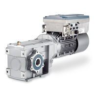
Siemens SINAMICS G110M Operating Instructions Manual (346 pages)
Distributed converter for SIMOGEAR geared motors
Brand:
Siemens
| Category:
Media Converter
| Size: 18.5 MB
Table of Contents
Instructions
4
Changes in this Manual
5
Table of Contents
7
Fundamental Safety Instructions
13
General Safety Instructions
13
Commissioning
16
Handling Electrostatic Sensitive Devices (ESD)
17
Safety Instructions for Electromagnetic Fields (EMF)
17
Industrial Security
18
Residual Risks of Power Drive Systems
20
About the Manual
21
Introduction
21
Advanced Commissioning
22
Technical Data
23
Description
25
Identifying the Components of the System
25
SINAMICS G110M Converter
26
Commissioning Tools
30
General Layout SINAMICS G110M System
31
Installation
37
Mechanical Installation
38
System Installation
41
System Installation
42
Installing the 24V Power Supply
54
Electrical Installation
58
SINAMICS G110M Electrical Data
58
Electrical Installation
59
Basic EMC Rules
60
Connections and Interference Suppression
60
Electrical Installation
60
EMC Installation Guidelines
60
Electrical Installation
61
Equipotential Bonding
61
Electrical Installation
62
Electrical Installation
63
Protective Conductor
63
Electrical Installation
64
Connection and Cables
65
Cable Protection
73
Connecting the PROFINET Interface
74
Terminal Assignment Dependent on Interface Configuration
75
Wiring Example for the Factory Settings
75
Connecting the Inverter to the Fieldbus
83
Fieldbus Version of the Control Module
83
Profinet
83
Connect the Converter to PROFINET
85
What Do You Need for Communication Via PROFINET
85
Configuring Communication to the Control
86
Installing GSDML
86
Integrating the Inverter in PROFIBUS
87
Profibus
87
What Do You Need for Communication Via PROFIBUS
87
Configuring the Communication Using SIMATIC S7 Control
88
Installing the GSD
88
Setting the Address
88
Communications Via AS-I
89
Setting the Address
90
Using the AS-I Programmer
92
Commissioning
95
Commissioning Guidelines
95
Prepare Basic Commissioning
96
Collecting Motor Data
97
Inverter Factory Setting
98
V/F Control or Speed Control
100
Basic Commissioning
101
Defining Additional Requirements for the Application
101
Motor Data Using P300 and P301
101
Basic Commissioning with DIP Switches
104
Basic Commissioning with IOP
110
P0015 Macros
111
Basic Commissioning with STARTER
117
Adapting the USB Interface
118
Generating a STARTER Project
119
Go Online and Start the Configuration Wizards - STARTER
120
Identify Motor Data - STARTER
123
Resetting the Safety Functions to the Factory Setting
124
Restoring the Factory Settings
124
Restore the Factory Settings (Without Safety Functions)
126
Advanced Commissioning
129
Overview of Converter Functions
129
Advanced Commissioning
130
Inverter Control
130
Switching the Motor on and off
130
Adapt the Default Setting of the Inputs and Outputs
131
Advanced Commissioning
131
Advanced Commissioning
132
Digital Inputs
132
Advanced Commissioning
133
Digital Outputs
133
Advanced Commissioning
134
Analog Inputs
134
Advanced Commissioning
135
Advanced Commissioning
136
Advanced Commissioning
137
Running the Motor in Jog Mode (JOG Function)
137
Advanced Commissioning
138
Advanced Commissioning
139
Control Via PROFIBUS or PROFINET with the Profidrive Profile
139
Advanced Commissioning
140
Advanced Commissioning
141
Control and Status Word 1
141
Advanced Commissioning
142
Advanced Commissioning
143
Advanced Commissioning
144
Control and Status Word 3
144
Advanced Commissioning
145
Structure of the Parameter Channel
145
Advanced Commissioning
146
Advanced Commissioning
147
Advanced Commissioning
148
Advanced Commissioning
149
Examples of the Parameter Channel
149
Advanced Commissioning
150
Extend Telegrams and Change Signal Interconnection
150
Advanced Commissioning
151
Advanced Commissioning
152
Control Via AS-I
152
Single Slave Mode
152
Slave-To-Slave Communication
152
Advanced Commissioning
153
Advanced Commissioning
154
Dual Slave Mode
154
Advanced Commissioning
155
Advanced Commissioning
156
Advanced Commissioning
157
Assignment Tables
157
Advanced Commissioning
158
Advanced Commissioning
159
Cyclic and Acyclic Communication Via CTT2
159
Advanced Commissioning
160
Cyclic Communication
160
Acyclic Communication - Manufacturer-Specific
161
Acyclic Communication - Standard
161
Advanced Commissioning
161
Advanced Commissioning
162
Advanced Commissioning
163
Switching over the Inverter Control (Command Data Set)
163
Advanced Commissioning
164
Advanced Commissioning
165
Overview
165
Setpoints
165
Advanced Commissioning
166
Analog Input as Setpoint Source
166
Advanced Commissioning
167
Electromechanical Potentiometer
167
Specifying the Setpoint Via the Fieldbus
167
Advanced Commissioning
168
Motorized Potentiometer as Setpoint Source
168
Advanced Commissioning
169
Advanced Commissioning
170
Fixed Speed as Setpoint Source
170
Advanced Commissioning
171
Advanced Commissioning
172
Overview of Setpoint Processing
172
Setpoint Calculation
172
Advanced Commissioning
173
Inhibit Direction of Rotation
173
Invert Setpoint
173
Advanced Commissioning
174
Skip Frequency Bands and Minimum Speed
174
Advanced Commissioning
175
Speed Limitation
175
Advanced Commissioning
176
Advanced Commissioning
177
Motor Control
177
Advanced Commissioning
178
V/F Control
178
Advanced Commissioning
179
Characteristics of U/F Control
179
Advanced Commissioning
180
Selecting the U/F Characteristic
180
Advanced Commissioning
181
Optimizing Motor Starting
181
Advanced Commissioning
182
Advanced Commissioning
183
Characteristics of the Closed Loop Speed Control
183
Vector Control with Closed Loop Speed Control
183
Advanced Commissioning
184
Select Motor Control
184
Advanced Commissioning
185
Optimizing the Speed Controller
185
Advanced Commissioning
186
Advanced Commissioning
187
Friction Characteristic
187
Advanced Commissioning
188
Advanced Commissioning
189
Moment of Inertia Estimator
189
Advanced Commissioning
190
Advanced Commissioning
191
Advanced Commissioning
192
Advanced Commissioning
193
Advanced Commissioning
194
Advanced Commissioning
195
Torque Control
195
Advanced Commissioning
196
Inverter Temperature Monitoring
196
Protection Functions
196
Advanced Commissioning
197
Advanced Commissioning
198
Advanced Commissioning
199
Motor Temperature Monitoring Using a Temperature Sensor
199
Advanced Commissioning
200
Advanced Commissioning
201
Advanced Commissioning
202
Protecting the Motor by Calculating the Motor Temperature
202
Advanced Commissioning
203
Overcurrent Protection
203
Advanced Commissioning
204
Advanced Commissioning
205
Limiting the Maximum DC Link Voltage
205
Application-Specific Functions
206
Unit Changeover
206
Siemens SINAMICS G110M Operating Instructions Manual (428 pages)
Distributed converter for SIMOGEAR geared motors
Brand:
Siemens
| Category:
Media Converter
| Size: 27.89 MB
Table of Contents
Changes in this Manual
5
Table of Contents
7
1 Fundamental Safety Instructions
13
General Safety Instructions
13
Equipment Damage Due to Electric Fields or Electrostatic Discharge
19
Warranty and Liability for Application Examples
20
Security Information
21
Residual Risks of Power Drive Systems
22
2 Introduction
23
About the Manual
23
3 Description
25
Identifying the Components of the System
26
SINAMICS G110M Converter
27
General Layout SINAMICS G110M System
31
Directives and Standards
36
4 Installation
39
Mechanical Installation
40
System Installation
44
Overview
44
Disassembly
46
Installation
48
Grounding the Terminal Housing
57
Installing the 24V Power Supply
57
Electrical Installation
62
SINAMICS G110M Electrical Data
62
EMC Installation Guidelines
64
Connections and Interference Suppression
64
Basic EMC Rules
64
Equipotential Bonding
65
Protective Conductor
67
Connection and Cables
69
Connecting the Motor to the Converter in a Star or Delta Connection
76
Cable Protection
78
Operation with Residual Current Protective Device (RCD)
80
Connecting the PROFINET Interface
81
Terminal Assignment Dependent on Interface Configuration
81
Wiring Example for the Factory Settings
82
Connecting the Converter to the Fieldbus
90
Fieldbus Version of the Control Module
90
Profinet
90
Connect the Converter to PROFINET
92
What Do You Have to Set for Communication Via PROFINET
92
Installing GSDML
93
Profibus
93
Integrating the Converter in PROFIBUS
93
What Do You Have to Set for Communication Via PROFIBUS
94
Installing the GSD
94
Set the PROFIBUS Address
95
Communications Via AS-I
96
Setting the Address
97
Using the AS-I Programmer
99
5 Commissioning
101
Commissioning Guidelines
101
Commissioning Tools
102
Prepare Commissioning
103
Collecting Motor Data
103
Converter Factory Setting
104
V/F Control or Speed Control
106
Minimum and Maximum Speed
107
Quick Commissioning
108
Motor Data Using P300 and P301
108
Quick Commissioning with DIP Switches
110
Commissioning with the IOP-2
115
P0015 Default Settings
118
Quick Commissioning with a PC
124
Creating a Project
125
Transfer Converters Connected Via USB into the Project
126
Go Online and Start the Commissioning Wizard
127
Selecting the Control Mode
129
Identify Motor Data
130
Restoring the Factory Settings
132
Saving Motor Data for Non-Standard Motors
132
Resetting the Safety Functions to the Factory Setting
134
Restore the Settings to the Factory Settings (Without Safety Functions)
135
Series Commissioning
137
6 Uploading the Converter Settings
139
Why Does an Upload Make Sense
139
Uploading to the Memory Card
140
Recommended Memory Cards
140
Automatic Upload
141
Message for a Memory Card that Is Not Inserted
142
Manual Upload with Startdrive
142
Safely Remove the Memory Card with Startdrive
144
Upload to a PC Using Startdrive
145
More Options for the Upload
146
7 Protecting the Converter Settings
147
Write Protection
147
Know-How Protection
149
Extending the Exception List for Know-How Protection
153
Activating and Deactivating Know-How Protection
154
Advertisement
Siemens SINAMICS G110M Operating Instructions Manual (382 pages)
sinamics series distributed converter for simogear geared motors
Brand:
Siemens
| Category:
Media Converter
| Size: 18.57 MB
Table of Contents
Legal Information
4
Changes in this Manual
5
Table of Contents
7
1 Fundamental Safety Instructions
13
General Safety Instructions
13
Equipment Damage Due to Electric Fields or Electrostatic Discharge
18
Warranty and Liability for Application Examples
18
Industrial Security
19
Residual Risks of Power Drive Systems
20
2 Introduction
23
About the Manual
23
3 Description
27
Identifying the Components of the System
27
SINAMICS G110M Converter
29
General Layout SINAMICS G110M System
33
Directives and Standards
38
4 Installation
41
Mechanical Installation
42
System Installation
46
Installing the 24V Power Supply
59
Electrical Installation
63
SINAMICS G110M Electrical Data
63
EMC Installation Guidelines
66
Connections and Interference Suppression
66
Basic EMC Rules
66
Equipotential Bonding
67
Protective Conductor
69
Connection and Cables
70
Connecting the Motor to the Inverter in a Star or Delta Connection
78
Cable Protection
79
Connecting the PROFINET Interface
81
Terminal Assignment Dependent on Interface Configuration
82
Wiring Example for the Factory Settings
82
Connecting the Inverter to the Fieldbus
90
Fieldbus Version of the Control Module
90
Profinet
90
What Do You Need for Communication Via PROFINET
92
Connect the Converter to PROFINET
92
Configuring Communication to the Control
93
Installing GSDML
93
Profibus
94
What Do You Need for Communication Via PROFIBUS
94
Integrating the Inverter in PROFIBUS
94
Configuring the Communication Using SIMATIC S7 Control
95
Installing the GSD
95
Setting the Address
95
Communications Via AS-I
96
Setting the Address
97
Using the AS-I Programmer
99
5 Commissioning
103
Commissioning Guidelines
103
Commissioning Tools
104
Prepare Commissioning
105
Collecting Motor Data
106
Inverter Factory Setting
108
V/F Control or Speed Control
109
Defining Additional Requirements for the Application
111
Quick Commissioning
111
Motor Data Using P300 and P301
111
Quick Commissioning with DIP Switches
113
Basic Commissioning with the IOP-2
119
P0015 Macros
122
Quick Commissioning with STARTER
127
Adapting the USB Interface
128
Generating a STARTER Project
129
Go Online and Start the Configuration Wizards - STARTER
130
Identify Motor Data - STARTER
133
Restoring the Factory Settings
134
Resetting the Safety Functions to the Factory Setting
135
Restore the Factory Settings (Without Safety Functions)
137
Siemens SINAMICS G110M Original Instructions Manual (344 pages)
Distributed Converter for SIMOGEAR geared motors
Brand:
Siemens
| Category:
Media Converter
| Size: 20.86 MB
Table of Contents
Legal Information
4
Changes in this Manual
5
Table of Contents
7
1 Fundamental Safety Instructions
13
General Safety Instructions
13
Safety Instructions for Electromagnetic Fields (EMF)
17
Handling Electrostatic Sensitive Devices (ESD)
17
Industrial Security
18
Residual Risks of Power Drive Systems
18
2 Introduction
21
About this Manual
21
Guide through this Manual
22
3 Description
23
Identifying the Components of the System
23
SINAMICS G110M Converter
24
Commissioning Tools
29
General Layout SINAMICS G110M System
30
4 Installation
35
Mechanical Installation
36
Dimensions of Converters and Motors
36
System Installation
39
Installation Procedure
43
Installing the 24V Power Supply
54
Electrical Installation
57
SINAMICS G110M Electrical Data
57
EMC Installation Guidelines
60
Connections and Interference Suppression
60
Basic EMC Rules
60
Equipotential Bonding
61
Connection and Cables
63
Cable Protection
73
Connecting the PROFINET Interface
74
Terminal Assignment Dependent on Interface Configuration
75
Wiring Example for the Factory Settings
75
5 Commissioning
83
Commissioning Guidelines
83
Basic Commissioning
84
Prepare Basic Commissioning
84
Collecting Motor Data
85
Inverter Factory Setting
87
V/F Control or Speed Control
89
Defining Additional Requirements for the Application
90
Motor Data Using P300 and P301
90
Restoring the Factory Settings
92
Basic Commissioning with DIP Switches
93
Basic Commissioning with IOP
98
P0015 Macros
100
Basic Commissioning with STARTER
106
Adapting the USB Interface
107
Generating a STARTER Project
108
Go Online and Start Wizard for Basic Commissioning
109
Identifying Motor Data
111
Using the AS-I Programmer
113
6 Adapt Inputs and Outputs
117
Digital Outputs
119
Analog Inputs
120
Deadband of the Analog Inputs
123
7 Configure Fieldbus
125
Fieldbus Version of the Control Module
125
Communication Via PROFINET
126
What Do You Need for Communication Via PROFINET
127
Connect the Converter to PROFINET
127
Configuring Communication to the Control
128
Select Telegram
128
Activating Diagnostics Via the Control
129
Communication Via PROFIBUS
129
What Do You Need for Communication Via PROFIBUS
129
Connect the Converter to PROFIBUS
130
Configuring the Communication Using SIMATIC S7 Control
130
Settings PROFIBUS DP Address with DIP Switches
130
Select Telegram
131
Profidrive Profile for PROFIBUS and PROFINET
133
Cyclic Communication
133
Control and Status Word 1
135
Control and Status Word 3
138
Extend Telegrams and Change Signal Interconnection
139
Structure of the Parameter Channel
141
Slave-To-Slave Communication
145
Acyclic Communication
146
Communications Via AS-I
146
Setting the Address
147
Single Slave Mode
149
Dual Slave Mode
151
Assignment Tables
153
Cyclic and Acyclic Communications Via CTT2
155
Cyclic Communication
156
Acyclic Communication - Standard
157
Acyclic Communication - Manufacturer-Specific
158
Siemens SINAMICS G110M Function Manual (344 pages)
Brand:
Siemens
| Category:
Inverter
| Size: 15.77 MB
Table of Contents
Change History
5
Table of Contents
7
1 Fundamental Safety Instructions
13
General Safety Instructions
13
Industrial Security
14
2 Introduction
15
About this Manual
15
Guide through the Manual
18
3 Description
19
About this Chapter
19
Overview of the Safety Functions
19
Overview of the Safety-Related Inverter Interfaces
21
Preconditions When Using the Safety Functions
22
Restrictions When Using Safety Functions
23
Recommendations for Stable Operation
26
Safe Torque off (STO)
27
Safe Brake Control (SBC)
30
Safe Stop 1 (SS1)
32
Application Example
33
Safely Limited Speed (SLS)
34
Safe Direction (SDI)
37
Application Examples
38
Safe Speed Monitoring (SSM)
39
4 Installing
41
Installing the Inverter
41
Connection Via Profisafe
42
Overview of Profisafe Connections
42
Profisafe Telegrams
46
Control Word 1 and Status Word 1 (Basic Functions)
47
Control Word 1 and Status Word 1 (Extended Functions)
48
Control Word 5 and Status Word 5
50
Activation Via F-DI
51
Safety Inputs
51
Wiring Examples
54
Connecting Sensors
54
Connecting Pre-Processing Devices
62
Evaluating Via F-DO
71
Safety Output
71
Connecting the Safety Output for SINAMICS G120D
72
Connecting the Safety Output for SINAMICS G120
73
Connecting a Motor Holding Brake to a Safe Brake Relay
74
5 Commissioning
77
Commissioning Guidelines
77
Configure Profisafe in the Higher-Level Control System
78
Configuring PROFIBUS Communication with Telegram 30 Via GSD
78
Example: Interface to the S7 Safety Program
80
Configuring PROFIBUS Communication Via Telegram 900 with the GSDML
82
Configuring Shared Device Communication Via PROFINET
82
Commissioning Tools
84
Resetting the Safety Function Parameters to the Factory Setting
85
Changing Settings
86
Setting Basic Functions
90
Interconnecting the "STO Active" Signal
91
Configuring Profisafe
92
Setting the Filter for Safety Inputs
94
Setting the Forced Checking Procedure (Test Stop)
98
Setting the Delay Time for SS1
99
Enabling SBC
100
Final Steps
101
Setting Extended Functions
103
Basic Settings
104
Enabling Safety Functions
104
Setting the Forced Dormant Error Detection (Test Stop)
104
Setting the Gear Ratio and Actual Value Tolerance
107
Setting Encoderless Actual Value Sensing
109
Setting Safety Inputs
111
Setting the Filter for Safety Inputs
113
Interconnecting the Signal for Fail-Safe Acknowledgment
119
Setting a Safety Output
120
Output Signal and Setting the Test Mode
120
Setting the Forced Dormant Error Detection (Test Stop)
125
Configuring Profisafe in the Converter
127
Setting SS1
130
Setting SS1 with Braking Ramp Monitoring
131
Setting SS1 with Acceleration Monitoring
134
Setting SLS
137
Setting the Monitoring Functions
137
Settings for Acceptance Test
141
Setting SSM
142
Setting SDI
146
Setting the Monitoring Functions
146
Settings for Acceptance Test
149
Final Steps
150
Offline Commissioning
153
Series Commissioning
155
Acceptance Tests for the Safety Functions
156
Acceptance Test
156
Reduced Acceptance Test after Expanding the Function
158
Siemens SINAMICS G110M Function Manual (244 pages)
Fieldbuses
Brand:
Siemens
| Category:
Inverter
| Size: 11.77 MB
Table of Contents
Table of Contents
5
1 Fundamental Safety Instructions
9
General Safety Instructions
9
Industrial Security
10
2 Introduction
11
Ethernet and PROFINET Protocols that Are Used
12
3 Communication Via PROFIBUS and PROFINET
15
Profidrive Profile
15
Cyclic Communication
15
Assigning Control and Status Words
19
NAMUR Message Word
27
Control and Status Word, Encoder
28
Position Actual Value of the Encoder
30
Extend Telegrams and Change Signal Interconnection
32
Data Structure of the Parameter Channel
33
Slave-To-Slave Communication
39
Acyclic Communication
40
Diagnostics Channels
45
Diagnostics with PROFINET
46
Diagnostics with PROFIBUS
47
Identification & Maintenance Data (I&M)
51
S7 Communication
52
Directly Accessing a SINAMICS G120 Converter from a SIMATIC Panel
52
Communication Via PROFINET
56
Inverter with PROFINET Interface
58
Integrating Inverters into PROFINET
59
PROFINET IO Operation
60
What Do You Need for Communication Via PROFINET
60
Configuring Communication to the Control
60
Installing GSDML
62
Activating Diagnostics Via the Control
62
Profienergy
62
General Inverter Behavior When in the Profienergy Energy-Saving Mode
63
Supported Profienergy Energy-Saving Modes
63
Settings and Displays for Profienergy in the Inverter
64
Control Commands and Status Queries
65
The Inverter as Ethernet Node
67
Communication Via PROFIBUS
69
Inverters with PROFIBUS Interface
70
What Do You Need for Communication Via PROFIBUS
72
Integrating Inverters into PROFIBUS
72
Configuring Communication to the Control System
73
Configuring the Communication Using SIMATIC S7 Control
73
Configuring the Communication with a Third-Party Control System
73
Installing the GSD
73
Setting the Address
74
Select Telegram
75
4 Communication Via Ethernet/Ip
77
Inverters with Ethernet/Ip Interface
78
Connect Converter to Ethernet/Ip
80
What Do You Need for Communication Via Ethernet/Ip
80
Configuring Communication Via Ethernet/Ip
81
Communication Settings
81
Special Issues if You Wish to Use the ODVA AC/DC Drive Profile
82
Supported Objects
83
Supported ODVA AC/DC Assemblies
98
Create Generic I/O Module
99
The Inverter as an Ethernet Station
100
Siemens SINAMICS G110M Function Manual (244 pages)
Fieldbus systems
Brand:
Siemens
| Category:
Media Converter
| Size: 8.2 MB
Table of Contents
Legal Information
4
Preface
5
Table of Contents
7
1 Fundamental Safety Instructions
11
General Safety Instructions
11
Warranty and Liability for Application Examples
11
Industrial Security
12
2 General Information
15
Ethernet and PROFINET Protocols that Are Used
16
3 Communication Via PROFIBUS and PROFINET
19
PROFIDRIVE Profile - Cyclic Communication
19
Assigning Control and Status Words
23
Control and Status Word 1
23
Control and Status Word 2
27
Control and Status Word 3
28
NAMUR Message Word
30
Control and Status Word, Encoder
31
Position Actual Value of the Encoder
33
Extend Telegrams and Change Signal Interconnection
35
Data Structure of the Parameter Channel
37
Application Examples
41
Slave-To-Slave Communication
43
PROFIDRIVE Profile - Acyclic Communication
44
Profidrive Profile - Diagnostic Channels
49
Diagnostics with PROFINET
50
Diagnostics with PROFIBUS
52
Identification & Maintenance Data (I&M)
56
S7 Communication
57
Directly Accessing a SINAMICS G120 Converter from a SIMATIC Panel
57
Communication Via PROFINET
61
Converter with PROFINET Interface
63
Integrating Inverters into PROFINET
64
PROFINET IO Operation
65
What Do You Have to Set for Communication Via PROFINET
65
Configuring Communication to the Control
65
Installing GSDML
67
Activating Diagnostics Via the Control
67
Profienergy
67
General Inverter Behavior When in the Profienergy Energy-Saving Mode
68
Supported Profienergy Energy-Saving Modes
68
Settings and Displays for Profienergy in the Inverter
69
Control Commands and Status Queries
70
The Inverter with PROFINET Interface as Ethernet Node
72
Communication Via PROFIBUS
74
Inverters with PROFIBUS Interface
75
What Do You Have to Set for Communication Via PROFIBUS
77
Integrating Inverters into PROFIBUS
78
Configuring Communication to the Control System
78
Configuring the Communication Using SIMATIC S7 Control
78
Configuring the Communication with a Third-Party Control System
78
Installing the GSD
79
Setting the Address
80
Select Telegram
81
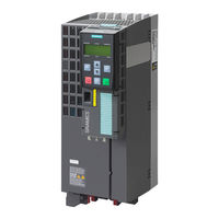
Siemens SINAMICS G110M Operating Instructions Manual (118 pages)
Intelligent Commissioning and Application Configuration Tool
Brand:
Siemens
| Category:
Control Panel
| Size: 8.7 MB
Table of Contents
Table of Contents
5
1 Safety Notes
9
2 Overview
11
Introduction
11
Layout and Functions
12
Screen Icons
15
Menu Structure
16
3 Installation
17
Fitting the IOP
17
Initial Set-Up
18
User Definable Labels for the Status Screen
22
Firmware and Language Upgrade
23
4 Wizards
25
Example Wizard
31
Basic Commissioning with IOP
33
Wiring Diagrams
36
5 Control
45
Custom Hand Mode
49
Startup in Hand Mode
53
Hand/Auto Disable
54
6 Menu
57
Overview
57
Diagnostics
58
Parameters
62
Up/Download
68
Custom Parameter Sets
69
Extras
73
I/O Editor
85
Write Protection
87
Know-How Protection
89
7 Options
105
Door Mounting Kit
105
Hand-Held Device
107
Siemens SINAMICS G110M Getting Started (100 pages)
Distributed converter for SIMOGEAR geared motors
Brand:
Siemens
| Category:
Industrial Equipment
| Size: 7.09 MB
Table of Contents
Table of Contents
5
Fundamental Safety Instructions
7
General Safety Instructions
7
Equipment Damage Due to Electric Fields or Electrostatic Discharge
13
Warranty and Liability for Application Examples
13
Industrial Security
14
Residual Risks of Power Drive Systems
16
Description
19
Identifying the Components of the System
19
SINAMICS G110M Converter
20
Compatible Motors
23
General Layout SINAMICS G110M System
23
Installation
29
Mechanical Installation
30
System Installation
34
Installation Procedures
34
Grounding the Terminal Housing
47
Installing the 24V Power Supply
47
Electrical Installation
51
SINAMICS G110M Electrical Data
51
Connections and Interference Suppression
53
Basic EMC Rules
54
Connection and Cables
55
Cable Protection
64
Commissioning
67
Commissioning Tools
67
Wiring Example for the Factory Settings
68
Inverter Factory Setting
70
P0015 Macros
71
Quick Commissioning with DIP Switches
77
Commissioning a Decentralized Drive with the IOP-2
83
Quick Commissioning with a PC
86
Creating a Project
87
Transfer Inverters Connected Via USB into the Project
88
Go Online and Start the Commissioning Wizard
89
Selecting the Control Mode
91
siemens SINAMICS G110M Getting Started (94 pages)
Distributed converter for SIMOGEAR geared motors
Brand:
siemens
| Category:
Media Converter
| Size: 8.55 MB
Table of Contents
Table of Contents
5
1 Safety Instructions
7
General Safety Instructions
7
Safety Instructions for Electromagnetic Fields (EMF)
10
Handling Electrostatic Sensitive Devices (ESD)
10
Industrial Security
11
Residual Risks of Power Drive Systems
12
2 Description
15
Identifying the Components of the System
15
SINAMICS G110M Converter
16
General Layout SINAMICS G110M System
23
3 Installation
27
Mechanical Installation
28
Dimensions of Converters and Motors
28
System Installation
31
Installation Procedures
31
Grounding the Terminal Housing
45
Installing the 24V Power Supply
46
Electrical Installation
49
SINAMICS G110M Electrical Data
49
Connections and Interference Suppression
51
Basic EMC Rules
52
Connection and Cables
53
Cable Protection
61
4 Commissioning
63
Commissioning Tools
63
Wiring Example for the Factory Settings
64
Factory Setting of the Inverter Control
66
V/F Control or Speed Control
67
P0015 Macros
68
Basic Commissioning with DIP Switches
70
Basic Commissioning with IOP
75
Basic Commissioning with STARTER
79
Adapting the USB Interface
79
Generating a STARTER Project
81
Go Online and Start Wizard for Basic Commissioning
82
Identifying Motor Data
84
Change Settings
85
Optimize the Drive Using the Trace Function
87
5 Troubleshooting
91
Status LED Overview
91
Siemens SINAMICS G110M Operating Instructions Manual (100 pages)
Intelligent Operator Panel. Intelligent commissioning and application configuration tool
Brand:
Siemens
| Category:
Control Panel
| Size: 7.29 MB
Table of Contents
Table of Contents
5
Safety Notes
7
Warnings and Cautions
7
Overview
9
Introduction
9
Layout and Functions
10
Screen Icons
13
Menu Structure
14
Installation
15
Fitting the IOP
15
Initial Set-Up
16
Firmware and Language Upgrade
20
Wizards
23
Example Wizard
31
Basic Commissioning with IOP
32
Wiring Diagrams
36
Control
45
Menu
49
Overview
49
Diagnostics
50
Parameters
54
Up/Download
59
Extras
60
Write Protection
70
Know-How Protection
72
Options
89
Door Mounting Kit
89
Hand-Held Device
91
Technical Data
95
Technical Specifications
95
Index
97
Siemens SINAMICS G110M Getting Started (92 pages)
Distributed converter for SIMOGEAR geared motors
Brand:
Siemens
| Category:
Industrial Equipment
| Size: 6.96 MB
Table of Contents
Table of Contents
5
1 Fundamental Safety Instructions
7
General Safety Instructions
7
Safety Instructions for Electromagnetic Fields (EMF)
11
Handling Electrostatic Sensitive Devices (ESD)
11
Industrial Security
12
Residual Risks of Power Drive Systems
12
2 Description
15
Identifying the Components of the System
15
SINAMICS G110M Converter
16
General Layout SINAMICS G110M System
18
3 Installation
23
Mechanical Installation
24
System Installation
28
Installation Procedures
28
Grounding the Terminal Housing
41
Installing the 24V Power Supply
41
Electrical Installation
44
SINAMICS G110M Electrical Data
44
Connections and Interference Suppression
46
Basic EMC Rules
47
Connection and Cables
48
Cable Protection
56
4 Commissioning
59
Commissioning Tools
59
Wiring Example for the Factory Settings
60
Inverter Factory Setting
62
V/F Control or Speed Control
63
P0015 Macros
64
Basic Commissioning with DIP Switches
71
Basic Commissioning with IOP
76
Basic Commissioning with STARTER
77
Adapting the USB Interface
77
Generating a STARTER Project
79
Go Online and Start the Configuration Wizards - STARTER
80
Identify Motor Data - STARTER
83
Using the AS-I Programmer
84
Troubleshooting
87
Siemens SINAMICS G110M Manual (62 pages)
Speed Control of a Startdrive with TIA Portal via PROFIBUS DP with Safety Integrated (via Terminal) and HMI
Brand:
Siemens
| Category:
Control Unit
| Size: 3.83 MB
Table of Contents
Legal Information
2
Table of Contents
3
1 Task
4
2 Solution
5
Solution Overview
5
Description of the Core Functionality
6
Configuring the Communication
6
Data Exchange
6
Hardware and Software Components Used
7
3 Setting up and Commissioning the Application
9
Wiring
9
IP and PB Addresses
10
PG/PC Settings
10
Setting the PROFIBUS Address at the G120 DP
11
Loading the Software
11
4 Operating the Application
19
Preconditions
19
Operation Via Digital Inputs
20
Monitoring and Parameter Access Via Operator Panel
21
Screens and Screen Navigation
21
Process Data Exchange
22
Parameter Access
25
Operator Control and Monitoring Via Monitoring Table
27
5 Functional Mechanisms of this Application
29
Functionality of Process Data Exchange
30
Accessing Process Data in the User Program of the Controller
30
Standardizing the Setpoint and Actual Values
31
Transfer Method
31
Control Word (STW1) and Status Word (ZSW1)
32
FB 11 "Process_Data
34
Parameter Access Functionality
38
Job and Response Structure
38
The Dbs "Read/Write_Drive_Parameters" and "Answer_From_Drive
39
FB 20 "Parameters
41
6 Configuration and Settings
45
Creating the Project Configuration
45
Configuration of the Components
45
Change Device of SINAMICS G120
53
Safe Torque off (STO) with Safety Integrated
54
Comments on Programming the SIMATIC S7-1200
58
Configuring the DPRD_DAT/DPWR_DAT Instruction
58
Configuring the RDREC/WRREC Instruction
60
7 Related Literature
61
8 History
62
Siemens SINAMICS G110M Manual (42 pages)
Control of a G120 or G110M with an Allen-Bradley controller (Compact/ControlLogix) via EtherNet/IP
Brand:
Siemens
| Category:
DC Drives
| Size: 2.15 MB
Table of Contents
Legal Information
2
Table of Contents
3
1 Introduction
5
Ethernet/Ip Overview
5
SINAMICS G Series Connectivity to Ethernet/Ip
5
2 Solution Overview
6
Used Components
6
3 Programming Overview
7
Configuration Choices
7
Aoi's for SINAMICS G Series Drives
8
AOI Types
8
4 SINAMICS G120 Add-On Instructions
9
Function Description
9
Telegram Descriptions
9
Telegram Type 1 for Simple Speed
9
Telegram Type 352 for Simple Speed
9
Telegram Type 111 for EPOS Mode
10
Basic Speed Control -Telegram 1
11
Functionality
11
Schematic Ladder Representation
11
Input and Output Parameters
11
Speed Control -Telegram 352
12
Functionality
12
Schematic Ladder Representation
13
Input and Output Parameters
13
EPOS Control
15
Functionality
15
Schematic Ladder Representation
15
Input and Output Parameters
16
Udts
18
5 Drive Configuration
19
Configuring IP Address of CU
19
Using a Freely Configurable Telegram
23
Example of "Free Telegram" Commissioning
24
6 Configuring a Generic Ethernet Module
25
Adding a New Module in Rslogix
25
Inserting the Module in an Rslogix Project
25
Configuring Network Parameters
26
Connection Parameters
27
Using IO Data
27
7 Using Aios in a New Application
28
Importing Aios
28
Installing L5K Files in Rslogix
28
Using the AOI
29
Adding AOI to an Rslogix Program
29
I/O Interface
30
8 Drive Parameter Access
31
Explicit Messaging
31
Using the MSG Instruction
32
9 Troubleshooting
37
I Can't Go Online with the Drive in Starter Using the Ethernet Cable
37
The Drive and the PLC Are Not Communicating
37
Advertisement
Related Products
Siemens SINAMICS G120C
Siemens SINAMICS G180
Siemens SINAMICS V20 Inverter
Siemens SINAMICS V10
Siemens SINAMICS Series
Siemens Sinamics ET 200pro FC-2
Siemens SINAMICS G110
Siemens SINAMICS G110D
Siemens SINAMICS G110D 6SL3511-0PE17-5AM0
Siemens SINAMICS G110D 6SL3511-0PE21-5AM0
Siemens Categories
Industrial Equipment
Controller
Control Unit
Oven
Washer
More Siemens Manuals
Login
Sign In
OR
Sign in with Facebook
Sign in with Google
Upload manual
Upload from disk
Upload from URL