Siemens SINAMICS G110M Getting Started
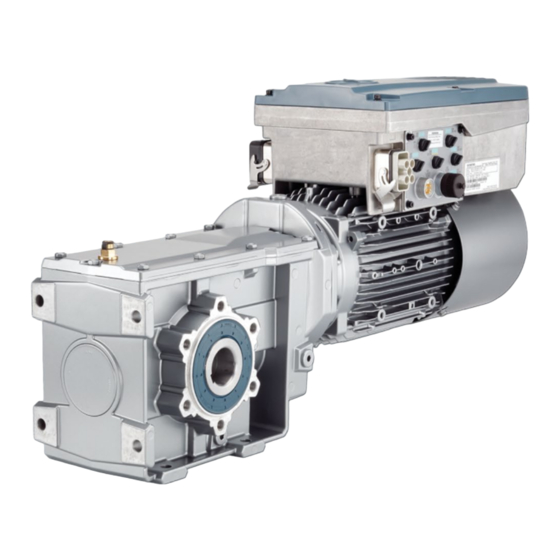
Distributed converter for simogear geared motors
Hide thumbs
Also See for SINAMICS G110M:
- Operating instructions manual (428 pages) ,
- Original instructions manual (344 pages) ,
- Function manual (244 pages)
Table of Contents
Advertisement
Quick Links
Advertisement
Table of Contents

Related Manuals for Siemens SINAMICS G110M


Summary of Contents for Siemens SINAMICS G110M
- Page 3 Fundamental safety ___________________ instructions ___________________ Description ___________________ SINAMICS Installation ___________________ Commissioning SINAMICS G110M Distributed converter for ___________________ SIMOGEAR geared motors Troubleshooting Getting Started Edition 04/2018, Firmware V4.7 SP10 04/2018, FW V4.7 SP10 A5E36100338B AG...
- Page 4 Note the following: WARNING Siemens products may only be used for the applications described in the catalog and in the relevant technical documentation. If products and components from other manufacturers are used, these must be recommended or approved by Siemens. Proper transport, storage, installation, assembly, commissioning, operation and maintenance are required to ensure that the products operate safely and without any problems.
-
Page 5: Table Of Contents
Residual risks of power drive systems ..................14 Description ............................17 Identifying the components of the system ................17 SINAMICS G110M converter ....................18 Compatible motors ........................21 General layout SINAMICS G110M system ................21 Installation ............................27 Mechanical Installation......................28 System Installation ........................32 3.2.1 Installation Procedures ...................... - Page 6 Table of contents 4.7.5 Identify motor data ......................... 90 Using the AS-i Programmer ....................92 Troubleshooting ............................ 95 Distributed converter for SIMOGEAR geared motors Getting Started, 04/2018, FW V4.7 SP10, A5E36100338B AG...
-
Page 7: Fundamental Safety Instructions
Fundamental safety instructions General safety instructions WARNING Electric shock and danger to life due to other energy sources Touching live components can result in death or severe injury. • Only work on electrical devices when you are qualified for this job. •... - Page 8 Fundamental safety instructions 1.1 General safety instructions WARNING Risk of electric shock and fire from supply networks with an excessively low impedance Excessively high short-circuit currents can lead to the protective devices not being able to interrupt these short-circuit currents and being destroyed, and thus causing electric shock or a fire.
- Page 9 Fundamental safety instructions 1.1 General safety instructions WARNING Electric shock due to unconnected cable shield Hazardous touch voltages can occur through capacitive cross-coupling due to unconnected cable shields. • As a minimum, connect cable shields and the conductors of power cables that are not used (e.g.
- Page 10 • If you come closer than around 2 m to such components, switch off any radios or mobile phones. • Use the "SIEMENS Industry Online Support app" only on equipment that has already been switched off. Distributed converter for SIMOGEAR geared motors...
- Page 11 Fundamental safety instructions 1.1 General safety instructions NOTICE Damage to motor insulation due to excessive voltages When operated on systems with grounded line conductor or in the event of a ground fault in the IT system, the motor insulation can be damaged by the higher voltage to ground. If you use motors that have insulation that is not designed for operation with grounded line conductors, you must perform the following measures: •...
- Page 12 Fundamental safety instructions 1.1 General safety instructions WARNING Unexpected movement of machines caused by inactive safety functions Inactive or non-adapted safety functions can trigger unexpected machine movements that may result in serious injury or death. • Observe the information in the appropriate product documentation before commissioning.
-
Page 13: Equipment Damage Due To Electric Fields Or Electrostatic Discharge
Fundamental safety instructions 1.2 Equipment damage due to electric fields or electrostatic discharge Equipment damage due to electric fields or electrostatic discharge Electrostatic sensitive devices (ESD) are individual components, integrated circuits, modules or devices that may be damaged by either electric fields or electrostatic discharge. NOTICE Equipment damage due to electric fields or electrostatic discharge Electric fields or electrostatic discharge can cause malfunctions through damaged... -
Page 14: Industrial Security
Siemens’ products and solutions undergo continuous development to make them more secure. Siemens strongly recommends that product updates are applied as soon as they are available and that the latest product versions are used. Use of product versions that are no longer supported, and failure to apply the latest updates may increase customer’s exposure... - Page 15 Fundamental safety instructions 1.4 Industrial security WARNING Unsafe operating states resulting from software manipulation Software manipulations (e.g. viruses, trojans, malware or worms) can cause unsafe operating states in your system that may lead to death, serious injury, and property damage. •...
-
Page 16: Residual Risks Of Power Drive Systems
Fundamental safety instructions 1.5 Residual risks of power drive systems Residual risks of power drive systems When assessing the machine- or system-related risk in accordance with the respective local regulations (e.g., EC Machinery Directive), the machine manufacturer or system installer must take into account the following residual risks emanating from the control and drive components of a drive system: 1. - Page 17 Fundamental safety instructions 1.5 Residual risks of power drive systems For more information about the residual risks of the drive system components, see the relevant sections in the technical user documentation. Distributed converter for SIMOGEAR geared motors Getting Started, 04/2018, FW V4.7 SP10, A5E36100338B AG...
- Page 18 Fundamental safety instructions 1.5 Residual risks of power drive systems Distributed converter for SIMOGEAR geared motors Getting Started, 04/2018, FW V4.7 SP10, A5E36100338B AG...
-
Page 19: Description
Description Identifying the components of the system The SINAMICS G110M is a complete converter system for controlling the speed of a three- phase motor. Each part of the system is shown in the following figure. Figure 2-1 Identifying the components of the system Distributed converter for SIMOGEAR geared motors Getting Started, 04/2018, FW V4.7 SP10, A5E36100338B AG... -
Page 20: Sinamics G110M Converter
Description 2.2 SINAMICS G110M converter SINAMICS G110M converter Overview The SINAMICS G110M system consists of the following components: Terminal Hous- The TH acts as the connection between the G110M ing (TH) and the motor. The TH replaces the normal motor terminal box. - Page 21 Description 2.2 SINAMICS G110M converter The Power Modules are designed for a specific power range and the Terminal Housings are designed to work with specific motors. The Terminal Housing not only allows the direct mounting onto a motor but specific cable glands and mains connectors are specified. All the various combinations of Power Modules, Terminal Housings (including the Control Modules) and Options are given in the tables below.
- Page 22 FS100/112 HanQ 4/2 / 7/8" 6SL3544-0QB02-1MA0 Every SINAMICS G110M is delivered with the following accessories: All variants ● PTC connection cable - this is the extension cable used to connect the PTC wires from the motor to the connection on the CPI board.
-
Page 23: Compatible Motors
Compatible motors Compatible motors for the SINAMICS G110M system The SINAMICS G110M is designed for mounting on SIMOGEAR geared motors. It is compatible with motors from frame size 71 to frame size 112. For an overview of which motors can be operated with SINAMICS G110M in combination with SIMOGEAR, please read FAQ 1097385577 at the following link: FAQ 1097385577 (https://support.industry.siemens.com/cs/us/en/view/109738577) - Page 24 Description 2.4 General layout SINAMICS G110M system Figure 2-2 General layout of the system - all variants except CU240M AS-i Distributed converter for SIMOGEAR geared motors Getting Started, 04/2018, FW V4.7 SP10, A5E36100338B AG...
- Page 25 Description 2.4 General layout SINAMICS G110M system Table 2- 4 Description and location of interfaces Item Description Item Description Power Module Blanking plate - to seal the opposite side of the Terminal Housing from which the CPI has been fitted.
- Page 26 Description 2.4 General layout SINAMICS G110M system Figure 2-3 SINAMICS G110M ASi General Layout Distributed converter for SIMOGEAR geared motors Getting Started, 04/2018, FW V4.7 SP10, A5E36100338B AG...
- Page 27 Description 2.4 General layout SINAMICS G110M system Table 2- 5 Description and location of interfaces Description Description Status LEDs AS-i connection and Aux power Optical I/O connection Digital inputs 0 and 1 Potentiometer Mains supply connection Mini USB connection Braking resistor & motor connection terminals Card reader (on underside of Power Communications &...
- Page 28 Description 2.4 General layout SINAMICS G110M system Distributed converter for SIMOGEAR geared motors Getting Started, 04/2018, FW V4.7 SP10, A5E36100338B AG...
-
Page 29: Installation
Use Only 75°C copper cable for all mains cables Due to the high internal temperatures, that may exist within the converter housing of the SINAMICS G110M converter, it is possible that any mains cables that are rated below 75°C could suffer the loss of their insulating properties. -
Page 30: Mechanical Installation
Installation 3.1 Mechanical Installation CAUTION Converter must not be used as a step or ledge The converter has not been designed to support a substantial weight and therefore must not be used as a step or a ledge. Should substantial weight be placed on the system it could result in severe damage to the equipment which could adversely affect the application and any persons coming in contact with the system. - Page 31 Installation 3.1 Mechanical Installation Clearance distance The G110M system requires a minimum clearance distance around and above the converter of 150 mm. Figure 3-2 G110M Clearance distances Terminal Housing dimensions and fixing points The Terminal Housing of the G110M system replaces the existing terminal box on the connected motor.
- Page 32 To ensure that the correct motor is selected the following sources of information should be consulted: ● The relevant system catalog, for example the SINAMICS G120 catalog. ● The relevant motor catalog. ● The Siemens "Configurator" online software application for dimensioning motors (Siemens motor configurator (https://eb.automation.siemens.com/goos/catalog/Pages/ProductData.aspx?catalogRegio n=WW&language=en&nodeid=10028832&tree=CatalogTree®ionUrl=%2F&autoopen= false&activetab=product#topAnch&activetab=config&))
- Page 33 Installation 3.1 Mechanical Installation Figure 3-4 Example of the data available from the Sizer program Mounting orientation The G110M system has been designed to operate in any orientation depending on the motor mounting configuration. Distributed converter for SIMOGEAR geared motors Getting Started, 04/2018, FW V4.7 SP10, A5E36100338B AG...
-
Page 34: System Installation
It is also possible that the SINAMICS G110M system is delivered as separate components, which will require the system to be fitted together before installation and commissioning can take place. - Page 35 Note Use only Non-Drive End (NDE) motor configurations The SINAMICS G110M has been designed to be used in conjunction with NDE motors. Do not use standard motor terminal box mountings with the SINAMICS G110M systems. See also...
- Page 36 Installation 3.2 System Installation To disassemble the Terminal Housing, the following procedure should be performed. 1. Remove the Communications & Power Interface (CPI) 1. Remove the CPI ribbon cable from the Control Module. 2. Unscrew the four screws holding the CPI in place on the Terminal Housing.
- Page 37 Installation 3.2 System Installation 4. Remove the internal braking resistor 1. Remove the internal resistor holding clamp. 2. Disconnect the brake resistor wires from the motor terminals (R2 and R1). 3. Slide the internal braking resistor out from the Terminal Housing.
- Page 38 Installation 3.2 System Installation Installation procedure Having dismantled the SINAMICS G110M Terminal Housing, the following procedure should be performed to complete the installation of the whole system. 1. Star and Delta Configuration Configure the motor terminals for either star or delta configura- tion depending upon the voltage requirement of the application and the mains input voltage.
- Page 39 LA/LE motors for mounting on SIMOGEAR gearboxes (http://support.automation.siemens.com/WW/view/en/60666 508). • If the SINAMICS G110M is ordered as a complete system, then all mechanical and electrical installation is completed in the factory prior to delivery. Distributed converter for SIMOGEAR geared motors...
- Page 40 Installation 3.2 System Installation 4. Connect the motor earth cable to the Terminal Housing 1. Feed the motor earth cable through the Terminal Housing. 2. Secure the motor earth cable to the Terminal Housing earthing post (1.5 Nm). 5. Connect the Terminal Housing motor terminals to the motor 1.
- Page 41 Terminal Housing. 2. Tighten the earthing post screw to 1.5 Nm. Note: If the SINAMICS G110M is ordered as a complete system, then all mechanical and electrical installation is completed in the factory prior to delivery. Distributed converter for SIMOGEAR geared motors...
- Page 42 Installation 3.2 System Installation 9. Connecting the mains cables (HANQ variant) 1. Ensure that the cable clamp has been removed. 2. Connect the HANQ L1, L2 and L3 connections to the L1, L2 and L3 connections on the mains connector. 3.
- Page 43 Installation 3.2 System Installation 11. Connecting the power-through cables (Glanded variant) In the glanded variant the power-through connections use a different methodology. The Terminal Housing terminals L1, L2 and L3 require two cables to be fitted to each terminal - this makes the maximum cable cross-section 2.5 mm .
- Page 44 Installation 3.2 System Installation 13. Fitting the blanking plate 1. Using the four screws, fit the blank plate to the side of the Terminal Housing. 2. Ensure that no cables or components are trapped between the blanking plate and the Terminal Housing seal, as this would adversely affect the IP rating of the Terminal Housing.
- Page 45 Installation 3.2 System Installation 16. Final connection and adjustments 1. Connect the temperature sensor connector into the connector at the top edge of the CPI. 2. Connect the small communications connector into the connector at the top of the CPI. 3.
- Page 46 For a complete explanation of the unswitched and switched 24 V supplies and their limitations, please read the FAQ at the following link: Unswitched and switched 24 V supply (http://support.automation.siemens.com/WW/view/en/26986267) After the system installation has been completed, the external electrical connections can be performed.
-
Page 47: Grounding The Terminal Housing
Installation 3.2 System Installation 3.2.2 Grounding the terminal housing Grounding the Terminal Housing To ensure that the Inverter is properly grounded and protected, an earthing cable MUST be fitted to the Terminal Housing of the G110M system. ● Connect the PE terminal on the left-hand side of the inverter to appropriate grounding point of the installation. - Page 48 Installation 3.2 System Installation At the base of the 24 V PSU housing is a cable gland opening (which is sealed with a blanking plug) which provides and entry point for the cables from an external braking resistor. The optional 24 V PSU can be ordered using the following article number: 6SL3555-0PV00-0AA0 A brief description of the layout and the connections of the 24 V PSU are given in the following figure.
- Page 49 Installation 3.2 System Installation ● When using the 24 V PSU there is no longer any isolation between the 24 V PSU and the digital outputs of the system. ● Since the 24 V PSU utilizes the DC link voltage to provide the 24 V supply to the Control Module, when the mains supply is disconnected, all power will be lost to the Control Module.
- Page 50 Installation 3.2 System Installation Using the external power supply with the G110M AS-i variant The 24 V power supply for the G110M AS-i variant is typically provided by the yellow and black AS-i cables that create the AS-i network. The yellow cable is the communications cable but also provides the power to: ●...
-
Page 51: Electrical Installation
Installation 3.3 Electrical Installation Electrical Installation 3.3.1 SINAMICS G110M Electrical data Power Module specifications - 3AC 380 V (-10%) ... 480 V (+10%) Table 3- 2 Rated Output, Input and Fuses Product Frame size Rated output Fuse* Rated output Rated input 3NA3…... - Page 52 * The optional 24 V PSU is an orderable item which is designed specifically for use with the SINAMICS G110M converter. The 24 V PSU is fitted to the terminal housing as shown in stalling the 24V power supply (Page 45). The external 24 V supply is sourced by the user and is...
-
Page 53: Connections And Interference Suppression
CAUTION Thermal stability of the system The SINAMICS G110M system is comprised of a motor and a converter which are designed to work together. The system can generate a significant amount of heat which can affect the performance of your application. -
Page 54: Basic Emc Rules
Installation 3.3 Electrical Installation Contactor coils, relays and solenoid valves must have interference suppressors to reduce high-frequency radiation when the contacts are opened (RC elements or varistors for AC current operated coils, and freewheeling diodes for DC current-operated coils). The interference suppressors must be connected directly on each coil. -
Page 55: Connection And Cables
Installation 3.3 Electrical Installation 3.3.4 Connection and cables The following block diagrams and tables describe the details and limitations of the connections on the converter. Wiring stripping The following components are delivered with pre-prepared cables and no wire stripping is necessary: ●... - Page 56 Installation 3.3 Electrical Installation Communications protocol Transfer rate or cable type Maximum overall length of cable 9.6 - 187.5 kbit/s 1000 m (3.280 ft) 500 kbit/s 400 m (1,312 ft) 1.5 Mbit/s 200 m (656 ft) 3, 6 and 12 Mbit/s 100 m (328 ft) PROFINET CAT5 network cable...
- Page 57 Installation 3.3 Electrical Installation Outline block diagram Figure 3-9 Outline block diagram SINAMICS CU240M and PM240M Distributed converter for SIMOGEAR geared motors Getting Started, 04/2018, FW V4.7 SP10, A5E36100338B AG...
- Page 58 Cable, connectors and tools specifications The detailed specifications for the cables, connectors and tools required to manufacture the necessary cables for the SINAMICS G110M are listed in the following documents and can be accessed using the relevant links: SINAMICS and motors for Single-Axis Drives D31 catalog (https://intranet.automation.siemens.com/mcms/infocenter/content/en/Pages/order_form.asp...
- Page 59 Installation 3.3 Electrical Installation Siemens supplementary product information (http://support.automation.siemens.com/WW/view/en/65355810) The connections that are detailed in this section relate to the physical connections that exist on the converter. Note NFPA compatibility These devices are intended only for installation on industrial machines in accordance with the "Electrical Standard for Industrial Machinery"...
- Page 60 Installation 3.3 Electrical Installation USS terminal diagram M12 connector, 5 Pole, male M12 connector, 5 Pole, female PROFIBUS terminal diagram M12 connector, 5 Pole, male M12 connector, 5 Pole, female PROFINET terminal diagram M12 connector, 4 Pole, female M12 connector, 4 Pole, female AS-i terminal diagram M12 connector, 5 Pole, female Distributed converter for SIMOGEAR geared motors...
- Page 61 Installation 3.3 Electrical Installation 24V Power supply - USS, PROFIBUS, PROFINET The unswitched 24 V power supply (1L+) is required for the device to function. ● Use a power supply with PELV (Protective Extra Low Voltage). ● For applications in USA and Canada: Use a power supply NEC Class 2. ●...
- Page 62 Adaption of inputs and outputs Further adaption of the inputs and outputs of the Inverter are possible, please refer to relevant section in the SINAMICS G110M Operating Instructions for further information. Distributed converter for SIMOGEAR geared motors Getting Started, 04/2018, FW V4.7 SP10, A5E36100338B AG...
- Page 63 Installation 3.3 Electrical Installation Terminal housing mains supply connections Type: HAN Q4/2 (Input and Output), 3 AC 380 V (-10%) ... 480 V (+10%) Important: The pinouts refer to the ac- tual connectors on the ter- minal housing. The terminal designation X1/3 is used because the mains input and output can be swapped around depend-...
-
Page 64: Cable Protection
Installation using power-through daisy chain The SINAMICS G110M system has been designed to allow a converter to utilize power- through to provide the mains power for a number of converters in a daisy chain. The maximum current limits for the daisy chain are given below: ●... - Page 65 Installation 3.3 Electrical Installation Figure 3-12 Daisy chaining power between Inverters Distributed converter for SIMOGEAR geared motors Getting Started, 04/2018, FW V4.7 SP10, A5E36100338B AG...
- Page 66 Installation 3.3 Electrical Installation Distributed converter for SIMOGEAR geared motors Getting Started, 04/2018, FW V4.7 SP10, A5E36100338B AG...
-
Page 67: Commissioning
Commissioning Commissioning tools Figure 4-1 Commissioning tools - PC or IOP Handheld Kit Distributed converter for SIMOGEAR geared motors Getting Started, 04/2018, FW V4.7 SP10, A5E36100338B AG... -
Page 68: Wiring Example For The Factory Settings
Optional memory card for storing and trans- 6SL3054-4AG00-2AA0 ferring the converter settings Internet: STARTER download (http://support.automation.siemens.com/WW/view/en/26233208) Internet:StartDrive download (http://support.automation.siemens.com/WW/view/en/68034568) Wiring example for the factory settings To ensure that the factory setting of the interfaces can be used, you must wire your drive as shown in the following examples. - Page 69 For a complete explanation of the unswitched and switched 24 V supplies and their limitations, please read the FAQ at the following link: Unswitched and switched 24 V supply (http://support.automation.siemens.com/WW/view/en/26986267) Distributed converter for SIMOGEAR geared motors Getting Started, 04/2018, FW V4.7 SP10, A5E36100338B AG...
-
Page 70: Inverter Factory Setting
Commissioning 4.3 Inverter factory setting Inverter factory setting Motor With its factory settings, the inverter is set up for an induction motor suitable for the power rating of the Power Module. Inverter interfaces The inputs and outputs and the fieldbus interface of the inverter have specific functions when set to the factory settings. -
Page 71: P0015 Macros
Commissioning 4.4 p0015 Macros Switching the motor on and off in the jog mode Figure 4-6 Jogging the motor with the factory settings In the case of inverters with a PROFIBUS or PROFINET interface, operation can be switched via digital input DI 3. The motor is either switched on and off via PROFIBUS – or operated in jog mode via its digital inputs. - Page 72 Commissioning 4.4 p0015 Macros Figure 4-8 Macro 9 - Motorized potentiometer (MOP) Figure 4-9 Macro 12 - Two-wire control with method 1 Figure 4-10 Macro 17 - Two-wire control with method 2 Distributed converter for SIMOGEAR geared motors Getting Started, 04/2018, FW V4.7 SP10, A5E36100338B AG...
- Page 73 Commissioning 4.4 p0015 Macros Figure 4-11 Macro 18 - Two-wire control with method 3 Figure 4-12 Macro 19 - Three-wire control with method 1 Figure 4-13 Macro 20 - Three-wire control with method 2 Distributed converter for SIMOGEAR geared motors Getting Started, 04/2018, FW V4.7 SP10, A5E36100338B AG...
- Page 74 Commissioning 4.4 p0015 Macros Figure 4-14 Macro 21 - Fieldbus USS Figure 4-15 Macro 28 - Conveyor with 2 fixed setpoints Figure 4-16 Macro 29 - Conveyer with potentiometer and fixed setpoint (default USS) Distributed converter for SIMOGEAR geared motors Getting Started, 04/2018, FW V4.7 SP10, A5E36100338B AG...
- Page 75 Commissioning 4.4 p0015 Macros Figure 4-17 Macro 30 - ASi Single slave with fixed setpoints (default ASi) Figure 4-18 Macro 31 - ASi Dual slave with fixed setpoints Distributed converter for SIMOGEAR geared motors Getting Started, 04/2018, FW V4.7 SP10, A5E36100338B AG...
- Page 76 Commissioning 4.4 p0015 Macros Figure 4-19 Macro 32 - ASi Single slave with analog setpoint Figure 4-20 Macro 33 - 4DI decentral conveyor with fieldbus Distributed converter for SIMOGEAR geared motors Getting Started, 04/2018, FW V4.7 SP10, A5E36100338B AG...
-
Page 77: Quick Commissioning With Dip Switches
Communications and Power Interface, including the Control Module comprise all the components that make up a standard Control Unit configuration; but when assembly and installing the SINAMICS G110M system, the Control Module requires a unique designation so that it can be easily identified in the installation procedures. - Page 78 Commissioning 4.5 Quick Commissioning with DIP switches Figure 4-22 DIP Switches location Distributed converter for SIMOGEAR geared motors Getting Started, 04/2018, FW V4.7 SP10, A5E36100338B AG...
- Page 79 Commissioning 4.5 Quick Commissioning with DIP switches Accessing the DIP switches DANGER Dangerous voltages and currents are present in the active converter When power is applied to the converter, even when it is not active, dangerous levels of voltage and current are present in the system. Before attempting the removal of any components of the system the following steps should be taken to ensure that the system is completely safe: 1.
- Page 80 Commissioning 4.5 Quick Commissioning with DIP switches The DIP switches allows specific functions of the converter to be set and are shown in the table below. Table 4- 2 Function of the DIP switches DIP switch Function ① Selects current or voltage input for the analog inputs. Temperature sensor - sets the type of temperature sensor fitted to the motor.
- Page 81 Commissioning 4.5 Quick Commissioning with DIP switches Figure 4-25 Commissioning DIP Switch 1 Distributed converter for SIMOGEAR geared motors Getting Started, 04/2018, FW V4.7 SP10, A5E36100338B AG...
- Page 82 Commissioning 4.5 Quick Commissioning with DIP switches Figure 4-26 Commissioning DIP Switch 2 Distributed converter for SIMOGEAR geared motors Getting Started, 04/2018, FW V4.7 SP10, A5E36100338B AG...
-
Page 83: Commissioning A Decentralized Drive With The Iop-2
Commissioning 4.6 Commissioning a decentralized drive with the IOP-2 Commissioning a decentralized drive with the IOP-2 Overview To perform the basic commissioning of a decentralized drive it is necessary to use the IOP-2 Handheld Kit (HHK). The details of the HHK and the associated cables are given in the Commissioning tools section of this manual. - Page 84 Commissioning 4.6 Commissioning a decentralized drive with the IOP-2 Select Enter Motor Data Select Motor Type Select Characteristic Select Continue Input Motor Frequency Input Motor Voltage Input Motor Current Input Power Rating Input Motor Speed Select Technology Applica- Select required Motor Data Select Macro Source tion ID function...
- Page 85 Commissioning 4.6 Commissioning a decentralized drive with the IOP-2 Input the Motor Speed Input Current Limit Select Motor Data ID option Input Encoder Type Input Encoder Pulses per rev Select Macro Source Input Maximum Speed Input Ramp-up time Input Ramp-down time Select Motor Temperature Select Motor Holding Brake Input Minimum Motor Spped...
-
Page 86: Quick Commissioning With A Pc
Commissioning 4.7 Quick commissioning with a PC Summary of settings - Select Save Settings Settings saved Continue Status Screen displayed On first ON command - Motor ID is performed Quick commissioning with a PC The screen forms that are shown in this manual show generally valid examples. The number of setting options available in screen forms depends on the particular inverter type. -
Page 87: Creating A Project
Commissioning 4.7 Quick commissioning with a PC 4.7.1 Creating a project Creating a new project Procedure 1. Start the Startdrive commissioning software. 2. In the menu, select "Project" → "New…". 3. Specify a name of your choice for the project. You have created a new project. -
Page 88: Transfer Inverters Connected Via Usb Into The Project
Commissioning 4.7 Quick commissioning with a PC 4.7.2 Transfer inverters connected via USB into the project Integrating the inverter into the project Procedure 1. Switch on the inverter power supply. 2. First insert a USB cable into your PC and then into the inverter. 3. -
Page 89: Go Online And Start The Commissioning Wizard
Commissioning 4.7 Quick commissioning with a PC 4.7.3 Go online and start the commissioning Wizard Procedure 1. Select your project and go online: 2. In the following screen form, select the inverter with which you wish to go online. 3. Once you are online, select "Commissioning" → "Commissioning Wizard": You have started the commissioning Wizard of the inverter. - Page 90 Commissioning 4.7 Quick commissioning with a PC Set the most important parameters to suit your application. Application: ● [0]: In all applications that do not fall under [3] ● [3]: Applications involving pumps and fans with optimized efficiency. The setting only makes sense for steady-state operation with slow speed changes.
-
Page 91: Selecting The Control Mode
Commissioning 4.7 Quick commissioning with a PC 4.7.4 Selecting the control mode Suitable applications and typical control properties U/f control or FCC (flux current con- Vector control without an encod- Vector control with encoder trol) without an encoder Application Horizontal conveyor technology Horizontal conveyor technol- Vertical conveyor technolo- •... - Page 92 Commissioning 4.7 Quick commissioning with a PC 4.7.5 Identify motor data Overview Using the motor data identification, the inverter measures the data of the stationary motor. In addition, based on the response of the rotating motor, the inverter can determine a suitable setting for the vector control.
- Page 93 Commissioning 4.7 Quick commissioning with a PC Procedure 1. Open the control panel. 2. Assume master control for the inverter. 3. Set the "Drive enables" 4. Switch on the motor. The inverter starts the motor data identification. This measurement can take several minutes.
- Page 94 Commissioning 4.8 Using the AS-i Programmer Using the AS-i Programmer Setting the slave address with the AS-i Address Programmer The Inverter contains two logical AS-i slaves. Either slave can be assigned an address in the range 1A...31A or 1B...31B. The addresses can be allocated to the slaves sequentially, for example, 3A and 4A, 10B and 11B or they can occupy the same number using extended addressing, for example, 20A and 20B.
- Page 95 Commissioning 4.8 Using the AS-i Programmer Setting the AS-i address of slave 2 Press the button; the display shows the text SEArcH followed by uSE 0. A small 0 is displayed to the left of the display and the number of the first slave that has already been allocated to slave 1 is shown at the bottom of the display.
- Page 96 Commissioning 4.8 Using the AS-i Programmer To change an existing address of a slave, the following procedure should be performed: Plug the AS-i Programmer into the addressing socket of the Inverter Turn the dial on the Programmer to the ADDR position. The display will indicate that this mode has been selected.
- Page 97 Troubleshooting LED status indicators The Power Module has number of dual-colour LEDs which are designed to indicate the operational state of the Inverter. The LEDs are used to indicate the status of the following states: ● General fault conditions ● Communication status The location of the various LEDs on the Power Module and Communications and Power Interface are shown in the figure below.
- Page 98 Troubleshooting Distributed converter for SIMOGEAR geared motors Getting Started, 04/2018, FW V4.7 SP10, A5E36100338B AG...