Table of Contents

Related Manuals for Speco N8NRE


Summary of Contents for Speco N8NRE
- Page 1 Network Video Recorder User Manual N8NRE/N16NRE/N32NRE/N4NRN/N8NRN/ N16NRN/ N4NRL/N8NRL/ N8NRP/ N16NRP/N64NR/N16NRD/N128NR Features and specifications are subject to change, please check www.specotech.com for firmware updates.
-
Page 2: Table Of Contents
This recorder is for indoor use only. Do not expose the recorder to rain or a moist environment. If any solids or liquids get inside the recorder’s chassis, please turn the device off immediately and get it checked by a qualified technician. ⚫ Do not try to repair the device by yourself without technical aid or approval from Speco Technologies’ Technical Support. Contents Introduction....................................... 1 1.1 Welcome ........................................... - Page 3 Notes& Contents NVR User Manual 5.3.5 Fisheye Settings ....................................25 PTZ .......................................... 26 6.1 PTZ Control Interface Introduction .................................. 26 6.2 Preset Setting ........................................29 6.3 Cruise Setting ........................................30 6.4 Cruise Group Settings ...................................... 31 6.5 Trace Settings ........................................31 6.6 Task Settings ........................................
- Page 4 Notes& Contents NVR User Manual 10.1 Target Detection View ....................................67 10.1.1 Human Body/Vehicle Detection View ..............................67 10.1.2 Face Detection/Match View ................................67 10.1.3 License Plate Detection/Recognition View ............................69 10.1.4 Object Attribute View ..................................71 10.2 Smart Search ......................................... 71 10.2.1 Face Search ......................................
- Page 5 Notes& Contents NVR User Manual 14.1.5 E-mail Configuration ..................................100 14.1.6 UPnP Configuration ..................................101 14.1.7 802.1X ......................................101 14.1.8 NAT Configuration .................................... 101 14.1.9 Cloud Upgrade ....................................102 14.1.10 Platform Access ....................................102 14.1.11 UPnP Report Access ..................................103 14.1.12 ONVIF ......................................
-
Page 6: Introduction
⚫ Basic Functions ⚫ Supports network device access including both Speco Technologies’ and third-party IP cameras (IPC) ⚫ This NVR supports the H.265 video coding stream and will also accept a mixed input of H.265 and H.264 IP cameras ⚫... - Page 7 Introduction NVR User Manual ⚫ Supports pre-recording and delay recording configuration of an event ⚫ Record Playback ⚫ Supports time scale operation in quick playback and the playback date and time can be set randomly by scrolling the mouse; the time interval of the time scale can be zoomed ⚫...
-
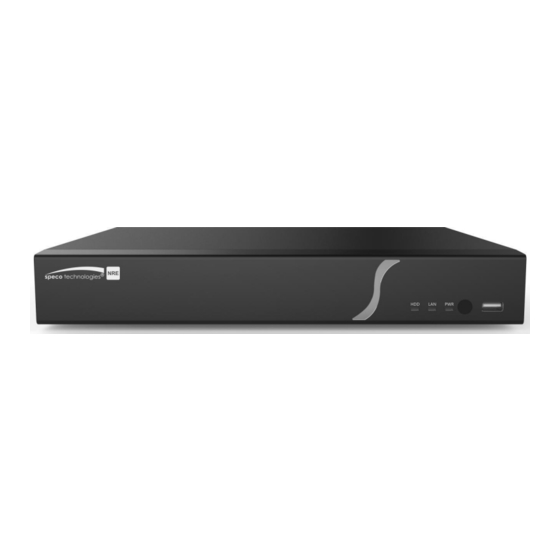
Page 8: Front Panel Descriptions
The light will be blue when there is power 1.4 Rear Panel Descriptions To quickly get started, connect the items below to your recorder in the following order. Please refer to the following figure (N8NRE shown for reference). Connect IP cameras to the PoE ports of the recorder. -
Page 9: Basic Operation Guide
Basic Operation Guide NVR User Manual 2 Basic Operation Guide 2.1 Startup & Shutdown Please make sure all connections are done properly before you power on the unit. Proper startup and shutdown are crucial to extending the life of your device. 2.1.1 Startup ①... -
Page 10: Mouse Control
Basic Operation Guide NVR User Manual Button Function Turn device on and off Power Button Record Button Start recording -/-- /0-9 Input number or choose camera Fn1 Button Currently no function Multi Button Choose multi screen display mode Next Button Switch the live image Go to sequence view mode Audio... -
Page 11: Common Button Operation
Basic Operation Guide NVR User Manual The interface has two types of input boxes. Refer to the above pictures. The left box is the number-only input box and the right box provides inputs of numbers, letters and punctuation characters. The introductions of keys on the input boxes are shown below. Button Meaning Button... -
Page 12: Ez Setup & Main Interface
EZ Setup & Main Interface NVR User Manual 3 EZ Setup & Main Interface 3.1 EZ Setup The disk icons will be shown on the top of the startup interface. You can view the number and status of each disk quickly and conveniently through these icons ( : no disk;... - Page 13 ⑤ Add Camera. Add cameras via PoE first before adding any cameras from the LAN. Speco cameras added via the PoE ports will automatically be added to the corresponding channel. To add cameras from the LAN, make sure all cameras are set to DHCP. Click “Refresh” to refresh the list of online IP cameras which are on the same local network as the NVR and then click to add the searched camera.
- Page 14 EZ Setup & Main Interface NVR User Manual Click to edit the searched IP camera as shown below left. Enter the new IP address, subnet mask, gateway, username and the password of the camera. You can check “Sync to IPC” to modify the IP address of the IPC via different network segments for being in the same network segment as the NVR.
-
Page 15: Main Interface
⑨ QR Code. Enable the NAT function in the interface or set it in the network configuration after exiting the wizard (please refer to 14.1.8 NAT Configuration for details). You can scan the QR Code through the Speco Blue App available for iOS and Android to view your cameras easily and securely. -
Page 16: Setup Panel
EZ Setup & Main Interface NVR User Manual Button Meaning Click to set the default playback time before starting instant playback (8.1 Instant Playback) or going to the playback interface for playback operations (8.2 Playback Interface Introduction); click to go to the playback interface. -
Page 17: Main Functions
EZ Setup & Main Interface NVR User Manual The setup panel includes seven modules. Each module provides some function entries with links for convenient operation. Take Camera module as an example. The Camera module provides convenient links such as “Add Camera”, “Edit Camera”, “Image Settings”, “Motion”, “Intelligence Analysis”... - Page 18 EZ Setup & Main Interface NVR User Manual ➢ AI/Event This module covers functions such as Sensor and Motion Alarm Handling and Alarm Out Settings. Please see Chapter 9 AI Event Management and Chapter 11 General Event Management for details. ➢...
-
Page 19: Camera Management
Camera Management NVR User Manual 4 Camera Management 4.1 Add/Edit Camera 4.1.1 Add Camera The network parameters of the NVR should be set before adding an IP camera (see 14.1.1 TCP/IP Configuration for details). Refer to the pictures below. Click Add Camera in the setup panel or in the top right corner of the preview window to open the “Add Camera”... -
Page 20: Edit Camera
Camera Management NVR User Manual username and password before clicking “Add” button). Click to delete the camera. Click “Default Password” to set the default username and password of each camera. Note: Some models may not support this function. Click Start→Settings→System→Basic→General Settings to check “Enable Add IPC by Zero Operation”. If the NVR has unoccupied channels, it can add IPC without any operation by restarting. -
Page 21: Add/Edit Camera Group
Camera Management NVR User Manual IP PoE cameras directly connected to the PoE ports of the NVR will be displayed automatically in the camera list. Refer to the picture above. The PoE camera directly connected to the PoE port has a prefix shown before its camera name. The prefix consists of PoE plus PoE port number. A PoE camera directly connected to the PoE port cannot be deleted from the camera list manually. - Page 22 Camera Management NVR User Manual Click “IP Planning” to go to the interface as shown below. This function supports searching other NVRs/DVRs that are in the same local network as the local NVR. The user may add camera channels of other NVRs/DVRs into the unoccupied channels of the local NVR. Click to edit the IP address, username or password and other information of the NVRs.
-
Page 23: Live View Introduction
Live View Introduction NVR User Manual 5 Live View Introduction 5.1 Live View Interface Introduction You should add cameras when first logging into the system (see 4.1.1 Add Camera for details). Refer to the interface shown below and drag one camera in the preview window to another window to exchange windows. -
Page 24: View Mode
Live View Introduction NVR User Manual 5.2 View Mode 5.2.1 Display Mode Set different screen modes and camera display sequences as needed and then save the display modes classified by surveillance areas, priorities and so on. Refer to the picture below. Double click one display mode in the display mode list to view the live images in this mode. ➢... -
Page 25: Quick Sequence View
Live View Introduction NVR User Manual name; click to delete the display mode. 5.2.2 Quick Sequence View You can start quick sequence view if the scheme has not been created. If the scheme has been created, please refer to 5.2.4 Scheme View in Sequence for details. -
Page 26: Scheme View In Sequence
Live View Introduction NVR User Manual You can also add camera group in the live view interface. Select “Single Channel Sequences” and then click to add camera group. Click to modify the group name and sequence interval. Click to delete the group. 5.2.4 Scheme View In Sequence Click Start→Settings→System→Basic→Output Settings to go to the interface as shown below. -
Page 27: Image Settings
Live View Introduction NVR User Manual 5.3.2 Image Settings Click Start→Settings→Camera→Image→Image Settings to go to the interface below. Select the camera and then set the brightness, contrast, saturation and hue of the camera. Click “Advanced” button or in the camera list on the right side of the interface to open “Image Adjust” interface and then set the relevant items. -
Page 28: Image Adjustment
Live View Introduction NVR User Manual 5.3.4 Image Adjustment Go to the live view interface and then click button on the tool bar under the camera window to go to the image adjustment interface. ➢ Image Adjustment Select the camera and then click “Image Adjustment” to go to image adjustment tab. Refer to the picture above. Drag the slider to set the camera’s brightness, contrast, saturation and hue value. - Page 29 Live View Introduction NVR User Manual Parameter Meaning Corridor 0°, 90°, 180° or 270° can be selected. (Only some cameras support this pattern) Pattern Image Mirror Turn the current video image horizontally. Image Flip Turn the current video image vertically. High frame rate mode, if is it enabled, the frame rate of the camera’s mainstream High FPS Mode can be set to 1080P/720P @60fps/50fps.
-
Page 30: Fisheye Settings
Live View Introduction NVR User Manual 5.3.5 Fisheye Settings Some models may not support this function. Click Start→Settings→Camera→Image→Fisheye Settings to go to the interface as shown below. Select the camera and the mode of fisheye and installation. -
Page 31: Ptz
NVR User Manual 6 PTZ 6.1 PTZ Control Interface Introduction You can control an IP dome or PTZ connected to the IP camera for PTZ control. Click on the tool bar at the bottom of the live preview window to go to the PTZ control interface as shown below. The direction, zoom, focus, iris and speed can be controlled in the small PTZ control window. - Page 32 NVR User Manual stop dragging the analog joystick. ➢ 3D Control Click the camera image on any area and the image will be centered on the clicked point. Refer to the picture as shown below. Drag the mouse from A to B to get a green rectangle and the rectangle area will be zoomed in. Refer to the picture as shown below.
- Page 33 NVR User Manual Adjust the dome’s direction and then click “Save Position” to save the current preset position (you can also click another preset in the preset list and then save the preset position after adjusting the dome’s direction); click in the preset list to call the preset;...
-
Page 34: Preset Setting
NVR User Manual In the “Add Cruise” window, select the cruise group name. After that, click “Play” to play the cruise groups in sequence. ➢ Trace Settings On the right panel, click to go to the trace settings tab. Click “Add” to add the trace name. Then click “OK” to save this name. Please refer to the following picture: After that, click “Start Record”... -
Page 35: Cruise Setting
NVR User Manual ➢ Add preset Select camera and then click “Add” button to add a preset; or click in the camera list on the right side of the interface to display the preset information of the dome and then click to add a preset. -
Page 36: Cruise Group Settings
NVR User Manual details. ➢ Edit Cruise Select the camera and cruise in the “Cruise” interface. Enter the new cruise name and then click to save the cruise name. Click “Add Preset” to add a preset to the cruise. Click to edit the preset. -
Page 37: Task Settings
6.7 Smart Tracking This function is only available with Speco Technologies’ AI PTZ cameras. Please add an AI PTZ camera to the NVR for this function to take effect. Smart Tracking: When people or vehicles cross the alarm line or intrude the predefined area, the PTZ camera can automatically track them and the... - Page 38 NVR User Manual target image will be automatically zoomed in and centered on the screen until the target disappears from the screen. After that, the PTZ camera will return to the tracking start position. To set smart tracking: 1. Click Settings→Camera→Smart Tracking to go to the smart tracking interface. 2.
-
Page 39: Record & Disk Management
Record & Disk Management NVR User Manual 7 Record & Disk Management 7.1 Record Configuration 7.1.1 Mode Configuration Please format the HDDs before recording (refer to 7.4.1 Disk Management for details). Click Start→Settings→Record→Mode Settings to go to the mode settings interface. You can set the record time under the “Manual Record Settings” and then click “Apply” to save your settings. There are two record modes: auto mode and scheduled mode. -
Page 40: Schedule Settings
Record & Disk Management NVR User Manual Video Encode: the available options will be H.265 and H.264 depending on what the camera supports. Resolution: the higher the resolution is, the clearer the image is. FPS: the higher the frame rate is, the more fluency the video has, with the tradeoff of using more storage. Bitrate Type: CBR and VBR are optional. - Page 41 Record & Disk Management NVR User Manual Set the schedule name and schedule time and then click “Add” to save the schedule. You can set day schedule or week schedule. : add button; : delete button. ➢ Set Day Schedule Click and then drag the cursor on the time scale to set record time;...
-
Page 42: Advanced Configuration
Record & Disk Management NVR User Manual Click “All” to set all week recording; click “Reverse” to swap the selected and unselected time in a week; click “Clear All” to clear all the selected area in a week. 7.1.3 Advanced Configuration Click Start→Settings→Record→Advanced to go to the interface below. -
Page 43: Record Mode
② Enable the intelligent alarm detection (object detection, exception, tripwire or intrusion) and draw alert surface or warning area of each IP camera. See 9 AI Event Management for details. The camera will start analytic recording once you finish the above steps. This function is only available for some Speco Blue IPCs. 7.4 Disk 7.4.1 Disk Management... - Page 44 Record & Disk Management NVR User Manual ④ Click “Close Encryption”. Unlock the disk: when one encrypted disk is transferred from another NVR to this NVR, it will be locked. You can select this locked disk and click “Unlock”. After you enter the password of its data encryption, its status will be “Read Only”. Now you can read the data of this disk but nothing can be written to it.
-
Page 45: Storage Mode Configuration
Record & Disk Management NVR User Manual e. Select a hot spare. In the physical disk interface, select the disk that is not in the array and click as shown in the following pictures. ⚫ RAID Rebuilding If one of your disks is defective, the disk indicator on the front panel will turn red. A warning tip will pop up if the relevant HDD exception alarm is set. -
Page 46: View Disk And S.m.a.r.t. Information
Record & Disk Management NVR User Manual By using a disk group, you can correspond a camera to disk (the recording data of the camera in the group will be stored into the disks in the same group). An NVR with e-SATA interface supports e-SATA recording. The added disks and cameras will be added into group one automatically. - Page 47 Record & Disk Management NVR User Manual In addition, you can view the plug-in or pull-out details of the HDD from the logs to check whether someone has made changes to your HDD. Click Start→Settings→System→View Log.
-
Page 48: Playback & Backup
Playback & Backup NVR User Manual 8 Playback & Backup 8.1 Instant Playback Click on the tool bar at the bottom of the preview camera window to play back the recording (click on the tool bar at the top of the live view interface to set the default playback time). - Page 49 Playback & Backup NVR User Manual Button Meaning Start button. Click to open area ②. Full screen button. Click to show full screen; click again to exit the full screen. Screen mode button. OSD ON button. Click to enable OSD; click it again to disable OSD. Quick channel selection button Stop button.
-
Page 50: Smart Playback
Playback & Backup NVR User Manual Click to switch the playback camera. Click and then check the Switch Camera camera in the popup window. Click “OK” to change the camera. Close Camera Click to close the playback camera. Introduction of area ④: Click to set the date;... -
Page 51: Smart Playback Settings
Draw quadrilateral. You can search the record in this quadrilateral after drawing it. Search by license plate number Search by face (only supported by N8NRE/N16NRE/N32NRE) Playback settings button Return button. Click to return to the previous interface. 8.3.1 Smart Playback Settings Click to set “Motion/Face/Vehicle video playback speed”, “Ordinary video playback speed”. -
Page 52: Smart Playback By Face Search
Playback & Backup NVR User Manual 8.3.3 Smart Playback by Face Search Before starting this function, the face recognition function must be enabled. Please see Face Recognition section for details. If your device doesn’t support such a function, please skip the following instructions. ①... -
Page 53: Smart Search By Object Attributes (Beta)
Before searching for objects by attributes, you must enable the video metadata (BETA) function of the camera. Please note that this function will only work with specific cameras running the newest firmware. Check with Speco Technologies’ technical support for models and firmware. Click... -
Page 54: Record Search, Playback & Export
Playback & Backup NVR User Manual 8.4 Record Search, Playback & Export The record data and the captured pictures can be exported through the network or USB (U disk or USB mobile HDD). The file system of the export devices should be FAT32 format. 8.4.1 EZ Search ①... -
Page 55: Time Search
Playback & Backup NVR User Manual Note: If you back up the record in private format, the system will back up a RPAS player to USB device automatically. The private format record can be played by RPAS player only. ⑤ Click “Playback” button to play the record in the playback interface (refer to 8.2 Playback Interface Introduction for details). Click “Exit” to exit the interface. -
Page 56: Event Search
Playback & Backup NVR User Manual interface. 8.4.3 Event Search ① Click Start→Search and Export→Event Search to go to “Event Search” tab as shown below. ② Check the event type in the interface as required. ③ Click to set the start time and end time on the top left of the interface. ④... -
Page 57: Snapshots
Playback & Backup NVR User Manual Click in the interface to play the record. Click to edit the tag name. Click to delete the tag. 8.4.5 Snapshots Click Start→Search and Export→Snapshots to go to “Snapshots” tab. The system will display all the captured images automatically in the list. Click to delete the image. -
Page 58: Ai Event Management
AI Event Management NVR User Manual 9 AI Event Management 9.1 Face Recognition Only some models support alarm trigger based on face comparison. If your device doesn’t support face recognition function, please skip the face database and face recognition instructions. The following are instructions on how to set up the Face Recognition function for the first time: Set face detection and alarm linkage →... -
Page 59: Face Database Management
⑩ Click “Apply” to save your settings. 9.1.2 Face Database Management This function is only available for the N8NRE/N16NRE/N32NRE. ① Click Start→Settings→AI/Event→AI Event→Face Recognition→Face Database to go to the following interface: For the initial setup, click “+” or “Add Group” to add groups. - Page 60 AI Event Management NVR User Manual ② Click “Add” and then click “Select Face” to add face images. You can add faces from the snapshot gallery or add external faces. Adding faces from snapshot gallery: Select search time or self define the search time and then click “Search” to search target faces. Next, select the desired faces and click “Select”.
-
Page 61: Face Recognition Settings
NVRs. 9.1.3 Face Recognition Settings This function is only available for the N8NRE/N16NRE/N32NRE. After the face database and face pictures are added, click “Face Recognition” to return to the face recognition setup interface. Click the “Recognition”... -
Page 62: License Plate Recognition
AI Event Management NVR User Manual interface and broadcast the audio. ⚫ Enable alarm output pulse (access control). ⚫ Trigger record, snapshot, alarm-out, buzzer, push, pop-up video, E-mail and pop-up message box as needed. The alarm linkage settings are similar to the face detection alarm (see 9.1.1 Face Detection Settings for details). ⚫... -
Page 63: Plate Database Management
AI Event Management NVR User Manual ⚫ Set the schedule. ⚫ Set the area and plate exposure as needed. Set the alarm area. Drag the mouse to draw a detection area. Click “Clear” to delete the alarm area. Set the blocked area. Select the number and then draw a blocked area. Up to 4 areas can be set up. After you set the blocked area, this area will not be detected. -
Page 64: License Plate Recognition Settings
AI Event Management NVR User Manual ② Enter the plate, vehicle owner and mobile phone number. ③ Select the vehicle type and group. ④ Enable validity period to set the start and end time ⑤ Finally click “OK” to complete. Select the added plate and then click to modify its information;... -
Page 65: Intrusion Detection
AI Event Management NVR User Manual ① Click Start→Settings→AI/Event→AI Event →Line Crossing to go to the following interface: ② Select the camera, enable line crossing detection by IPC and set the duration. ③ Set the schedule. ④ Select the direction. Direction: A<->B, A->B and A<-B optional. -
Page 66: Abandoned/Missing Object Detection
AI Event Management NVR User Manual ⑦ Click “Detection Target” to choose the detection target and the sensitivity. The detection target includes people, vehicles and non-vehicles. ⑧ Click “Trigger Mode” to configure intrusion detection alarm linkage items. ⚫ Enable or disable “Record”, “Snapshot”, “Push”, “Alarm-out”, “Preset”, “Buzzer”, “Pop-up Video” and “E-mail”. The alarm linkage settings are the same as the face detection alarm (see 9.1.1 Face Detection Settings for details). -
Page 67: Target Counting
AI Event Management NVR User Manual Crowd Density Configuration: Alarms will be triggered if the crowd density exceeds the set threshold value in the pre-defined area. ① Click Start→Settings→AI/Event→AI Event→Crowd Density to go to the interface below. ② Select the camera, enable crowd density detection and set the schedule, duration, refresh frequency and alarm threshold. Refresh Frequency: Refers to the refresh time of the detection result report. - Page 68 AI Event Management NVR User Manual ⑥ Click “Apply” to save your settings. ⚫ Human/Motor Vehicle/Non-Motor Vehicle Counting The information of human/motor vehicle/non-motor vehicle can be calculated and sent by day, by week and by month, so that you can receive and analyze these statistics on time.
-
Page 69: Tampering Detection
9.9 Fire Detection Fire detection is only available if you are using the appropriate Speco Technologies’ Thermal Camera. Please note this is only intended as a supplement to official fire detection methods and should not be relied on as a primary alert source. -
Page 70: Temperature Detection
④ Click “Apply” to save your settings. 9.10 Temperature Detection Temperature Detection is only available if you are using the appropriate Speco Technologies’ Thermal Camera. Temperature Measurement: When a temperature of the pre-defined point/line/area exceeds the temperature threshold value, alarms will be triggered. -
Page 71: Video Metadata (Beta)
AI Event Management NVR User Manual “Pop-up Video”, “Pop-up Message Box” and “E-mail”. The alarm linkage settings are the same as the face detection alarm (see 11.1 Sensor Alarm for details). ⑥ Click “Apply” to save your settings. 9.11 Video Metadata (BETA) Please note that this feature is still in BETA and is not recommended for official implementation into your security environment. -
Page 72: Intelligent Analytics
10.1.1 Human Body/Vehicle Detection View This feature only works with the appropriate Speco Blue cameras. The setup steps are as follow: ① Enable the line crossing/Intrusion/Target counting function of IPCs/NVR, draw the line or area and choose the detection target (see 9.3 Line crossing Detection and 9.4 Intrusion Detection for details). - Page 73 Intelligent Analytics NVR User Manual For unknown faces, you can select one and click under the captured face to register this face (see the picture below); click to quickly go to the smart face search interface where you can search for matching facial information; click to quickly go to the smart face playback interface;...
-
Page 74: License Plate Detection/Recognition View
Note: if you enter a remark when adding a face picture to the face database, that information (instead of the person’s name), will be shown under the picture after a successful recognition. 10.1.3 License Plate Detection/Recognition View License plates can only be captured and matched if a compatible Speco Blue ANPR camera is added and enabled. The setup steps are as follows:... - Page 75 Intelligent Analytics NVR User Manual ① Enable the Plate Detection function (See 9.2.1 License Plate Detection Settings for details). Once enabled, you can see the captured plates displayed in the live view interface shown below: Put the cursor on the captured plate picture and then click to register this plate as shown below: Click to view the captured detail information.
-
Page 76: Object Attribute View
Intelligent Analytics NVR User Manual Click the captured plate picture to open a detailed information window. You can view the snapshot picture, original picture, snapshot time, camera, etc. Click “More” to view the ID information of the target and export the captured picture. Click “Search” to go to the vehicle search interface. Click “Playback”... - Page 77 Intelligent Analytics NVR User Manual ② Click to choose a face detection camera. ③ Select all events, successful recognition, or stranger. ④ Click “Search” to search all face pictures. You can view face pictures by time or by camera. ⑤ Click the searched face picture to play in the small playback window; select a face picture and click “Backup” to export it. Click “Original”...
- Page 78 Intelligent Analytics NVR User Manual To add a single target face from recent faces: a. Choose the face. b. Click “Select Face”. To add a single target face from the face database: a. Click “More” to choose groups. b. Select a target face and click “Select Face”. To add a single target face from the snapshot gallery: a.
-
Page 79: Track Playback
Intelligent Analytics NVR User Manual ⚫ View Image by List Click “List” tab to view images by time as shown below. Click the searched image to play a clip. Click to view the detailed information of the comparisons to the target face. ⚫... - Page 80 Intelligent Analytics NVR User Manual Note: Tracking will only work if two or more cameras have viewed and recorded the subject. Descriptions of buttons on the tracking interface Fixed Window Frame Followed Window Fast Forward(x2;x4) Exchange Window Normal Speed Stop Start/Stop Track Play Edit Map...
-
Page 81: Face Search By Snapshot
Intelligent Analytics NVR User Manual Click “Load Map” to add a map. Drag the camera names onto and around the map to change their locations. Choose a color from the left color list to set your favorite color for camera names. Load Map: ①... -
Page 82: Vehicle Search
Intelligent Analytics NVR User Manual You can also select the attributes of people to filter (like gender, age, mask-wearing status, glasses-wearing status, color of clothes, etc.). Please note the metadata attribute feature is still in BETA and results may not be completely accurate. Click a searched picture to play the recording in the small window on the left. -
Page 83: Combination Search
Click “Track” to view the track of the vehicle. Note: Only one plate can be traced at a time and two or more Speco Blue ANPR cameras must have detected this vehicle to create a track to follow. The track setup steps are like the face track setup steps. Please refer to face track settings for details. -
Page 84: Face Attendance
Intelligent Analytics NVR User Manual ① Select the time. ② Select cameras. ③ Select events as needed, such as face detection, face match, intrusion and tripwire. Note: Face match events (successful recognition & stranger) are available for some models. If Face Match-Successful Recognition event is selected, you can choose “Detail Chart”... -
Page 85: Face Check-In
Intelligent Analytics NVR User Manual Click to view the detailed attendance information. In this interface, click to go to the face search interface. 10.5 Face Check-In Click Start→Intelligent Analytics→Face Attendance to go to the interface below. The search steps of face check-in are as follows. ①... -
Page 86: General Event Management
General Event Management NVR User Manual 11 General Event Management 11.1 Sensor Alarm To ensure complete setup of the Sensor Alarm function, you should enable the sensor alarm of each camera and then immediately set up the alarm handling for that camera. ①... -
Page 87: Motion Alarm Handling Configuration
General Event Management NVR User Manual ② Select a camera, enable motion, and set the sensitivity and duration for that camera. Sensitivity: The higher the value is, the more sensitive it will be to motion. You should adjust the value according to the practical conditions since the sensitivity is influenced by background color and time (day or night). -
Page 88: Ipc Offline Settings
General Event Management NVR User Manual 11.4 IPC Offline Settings ① Click Start→Settings→AI/Event→IPC Offline Settings to go to the interface as shown below. ② Enable or disable “Snapshot”, “Push”, “Alarm-out”, “Preset”, “Buzzer”, “Pop-up Video”, “Pop-up Message Box” and “E-mail”. The IPC Offline setup is similar to that of the sensor alarm (see 11.1 Sensor Alarm for details). -
Page 89: E-Mail
General Event Management NVR User Manual ② Set the delay time and the schedule of each alarm-out. You can click “Edit Schedules” to edit the schedules (see 7.1.2 Schedule Settings for details). ③ Click “Apply” to save your settings. You can click “Test” to test the alarm output. 11.6.2 E-mail Click Start→Settings→AI/Event→Event Notification→E-mail to go to the e-mail configuration interface. -
Page 90: Digital Deterrent
General Event Management NVR User Manual 11.6.6 Digital Deterrent Click Start→Settings→ AI/Event →Event Notification→Digital Deterrent to go to the interface as shown below. Camera audio settings: You can set voice broadcast up for perimeter alert cameras. Select the camera, voice, broadcast times, volume, and language and then click “Apply” to save your settings. -
Page 91: Light
General Event Management NVR User Manual In this interface, you can set the schedule and volume of the local audio alarm. Click “Manage” to set the schedule. Click “Add” to upload the audio file. Choose the uploaded audio file and then click “Listen” to listen to it; click “Delete” to delete this file. 11.6.7 Light Click Start→Settings→Alarm→Event Notification→Light to go to the interface as shown below. -
Page 92: Manual Alarm
General Event Management NVR User Manual 11.7 Manual Alarm Click on the tool bar at the bottom of the live preview interface to open this window. Click “Trigger” to start alarm. Click “Clear” to stop alarm. 11.8 View Alarm Status Click Start→Settings→Alarm→Alarm Status or click on the tool bar at the bottom of the live preview interface to view the alarm status. - Page 93 General Event Management NVR User Manual By default, all alarm linkages of all channels and sensor alarms will be disarmed after clicking “One Key Disarm”. You can also self-define the channels and sensors you want to disarm by clicking “Add”. Only the selected channels and sensors will be disarmed by clicking “One Key Disarm”.
-
Page 94: Parking Lot Management
NVR User Manual 12 Parking Lot Management You can manage a parking lot through the NVR. This function will only work using compatible Speco Blue ANPR License Plate Cameras. 12.1 Parking Lot Settings Click Start→Intelligent Analytics→Parking Lot Management to go to the parking lot setup interface. -
Page 95: Search Vehicle Entry/Exiting Records
General Event Management NVR User Manual In this interface, you can view the detailed information of the parking lot, including the total parking spaces, remaining parking spaces, number of vehicles entering today, number of vehicles exiting today and vehicle entry/exit records. Only vehicles added into the plate database are allowed to pass automatically. - Page 96 General Event Management NVR User Manual...
-
Page 97: Account & Permission Management
Account & Permission Management NVR User Manual 13 Account & Permission Management 13.1 Account Management Click Start→Settings→Account and Authority→Account→Edit User to go to the interface shown below: Area ① displays the user permissions. Area ② displays the user list. Click the user in the list to display its user permissions in area ①. There are three default permission groups (“Administrator”, “Advanced”... - Page 98 Account & Permission Management NVR User Manual ➢ Edit Security Question You can only set password security for admin. Click “Edit Security Question” and then set questions and answers in the popup window. If you forget the password for admin, please refer to Q4 in Appendix A FAQ for details. The passwords of other users can be recovered by admin or the users that have the “Account and Authority”...
-
Page 99: User Login & Logout
Account & Permission Management NVR User Manual 13.2 User Login & Logout Login: Click Start→Login or directly click the preview interface and then select username and enter the password in the popup window. Click “Login” button to log in the system. Logout: Click Start→Logout or click Start→Shutdown to open the “Shutdown”... -
Page 100: Edit Permission Group
Account & Permission Management NVR User Manual 13.3.2 Edit Permission Group Go to the “Edit Permission Group” interface and then click in the group list to edit the permission group (the operations of the “Edit Permission Group” are similar to that of the “Add Permission Group”, please see 13.3.1 Add Permission Group for details). Click to save the group as a new group. -
Page 101: Network Security
Account & Permission Management NVR User Manual 13.6 Network Security Click Start→Settings→Account and Authority→Security→Network Security to go to the interface below. ARP (Address Resolution Protocol) Guard: This function can protect the LAN from ARP attacks and increase the network stability. If it is enabled, you can enable auto gateway MAC or manually set gateway MAC. -
Page 102: Device Management
Device Management NVR User Manual 14 Device Management 14.1 Network Configuration 14.1.1 TCP/IP Configuration Click Start→Settings→Network→TCP/IP to go to the interface below. Check “Obtain an IPv4 address automatically”, “Obtain an IPv6 address automatically” and “Obtain DNS automatically” to get the network addresses automatically, or manually enter the network addresses. You can modify the MTU value according to the network condition (MTU, Maximum Transmission Unit, can be modified according to network condition for higher network transmission efficiency). - Page 103 Device Management NVR User Manual HTTP Port: the default HTTP port of the NVR is 80. For security, the port number can be changed another number such as 81. The port is mainly used for web client access. If you want to access the NVR through a web browser, you should enter the IP address plus HTTP port in the address bar of the web browser like http://192.168.11.61:81.
-
Page 104: Pppoe Configuration
14.1.4 DDNS Configuration The DDNS is used to control the dynamic IP address through a domain name. Speco Technologies provides free DDNS service with US-based servers. You can access the NVR easily if the DDNS is enabled and configured. Click Start→Settings→Network→DDNS to go to the interface shown below. The default... -
Page 105: E-Mail Configuration
Device Management NVR User Manual selected DDNS name is invalid or taken, please select another domain name. Click on test to confirm if the DDNS Domain is OK. If so, you may now go to [your domain name].specoddns.net with a browser and access your recorder remotely. 14.1.5 E-mail Configuration Click Start→Settings→Network→E-mail to go to the interface below. -
Page 106: Upnp Configuration
Device Management NVR User Manual 14.1.6 UPnP Configuration By UPnP you can access the NVR through the web client which on the WAN via a router without port mapping. ① Click Start→Settings→Network→UPnP to go to the interface below. ② Make sure the router supports UPnP function and the UPnP is enabled in the router. ③... -
Page 107: Cloud Upgrade
Check “Enable” and then select the NAT server address. Click “Apply” to save your settings. You can scan the QR Code on the Speco Blue app installed on a mobile phone or tablet PC to quickly add the device to the server list of the mobile app. -
Page 108: Upnp Report Access
Device Management NVR User Manual Platform Access ① Set “Access Type” as “Platform Software” and select “Enable” as shown below. ② Check the IP address and port of the transfer media server in the NVMS. The default server port for auto report is 2009. If it is modified, please go to the transfer media interface to verify. -
Page 109: Network Status
Device Management NVR User Manual Note: when adding the device to a third-party platform with ONVIF protocol, please check “Enable ONVIF” first and then enter the username and password created in the above interface. 14.1.13 Network Status Click Start→Settings→Network→Network Status to view the network status to view network status conveniently. Click Start→Settings→Network→Network Status Detection. -
Page 110: Date And Time Configuration
Device Management NVR User Manual Device Name: The name of the device. It may display on the client end or CMS to help users recognize the device remotely. Video Format: Two modes: PAL and NTSC. Select the video format according to the camera. Main Output: Enable “Fixed display resolution”... -
Page 111: Recorder Osd Settings
Device Management NVR User Manual 14.2.3 Recorder OSD Settings Click Start→Settings→System→Basic→Recorder OSD settings to go to the interface below. OSD name and icon can be enabled here. 14.2.4 PoE Settings ⚫ PoE Management Click Start→Settings→System→Basic Settings→PoE Power Management to go to the interface below. This function is only available for recorders with built-in PoE. -
Page 112: Factory Default
Device Management NVR User Manual ⚫ PoE Plug-and-Play Settings The PnP function of each PoE port is enabled by default. You can directly connect a PoE IPC to the PoE port of the NVR with a network cable. You can also connect a PoE IPC to the NVR via a PoE switch by the following steps: 1. -
Page 113: Backup And Restore
Device Management NVR User Manual 14.5 Backup and Restore You can back up the configuration file of the NVR and export the file to other storage devices; in this way, you can implement the configuration to other NVRs of the same model and save setup time. Insert the USB storage device into a USB interface on the NVR and then click Start→Settings→System→Maintenance→Backup and Restore to go to the interface. -
Page 114: View System Information
Device Management NVR User Manual Choose the log file in the list and then click “Export” button to export the log file. Click on the “Content” title bar to open a menu list. Using the check box, check contents on the menu list and then the log list will show only the checked log contents. Click to play the video log. -
Page 115: Remote Surveillance
① Enable NAT in the NVR. Refer to 14.1.8 NAT Configuration for details. ② Scan the QR Code through the Speco Blue App available for iOS and Android to easily and securely view your cameras. ③ Run the Speco Blue app, go to the “Add Device” interface and then click to scan the QR Code of the NVR (Go to Start→Settings→System→Information→Basic to view the QR Code of the NVR). -
Page 116: Web Remote Control
Remote Surveillance NVR User Manual ➢ PPPoE Access ① Click Start→Settings→Network→PPPoE to go to the “PPPoE” interface. Check “Enable” in the “PPPoE settings” and then enter the username and password provided by your ISP. Click “Apply” to save your settings. ②... -
Page 117: Remote Preview
Remote Surveillance NVR User Manual The buttons and icons on the top right corner of the remote interface are introduced as follows. admin: the current login username. Logout: click to log out and return to the login interface. Modify Password: click to change the password of the currently active user. Enter the current password and then set a new password in the popup window. - Page 118 Remote Surveillance NVR User Manual on the left panel stands for the number of online cameras; the right number 3 stands for the number of all the added cameras. Enter the camera name in the search box and then click to search for the camera.
- Page 119 Remote Surveillance NVR User Manual Click one camera window in the preview area and then click to set the camera’s live view stream and record stream to main stream in manual record mode; click to set the camera’s live view stream and record stream to sub stream. In sub stream tab, set the resolution, FPS and bitrate and then click “Apply”...
-
Page 120: Remote Playback
Remote Surveillance NVR User Manual Button Meaning Click to view the trace list. Click to add a trace; click Trace play the trace click to start record. 15.4.2 Remote Playback Click “Playback” in the remote interface to go to the playback interface. ①... -
Page 121: Remote Configuration
Remote Surveillance NVR User Manual 15.4.5 Remote Configuration Click “Function Panel” in the remote interface and then configure the camera, record, alarm, disk, network, account and authority and system of the NVR remotely. All these settings are the same as the settings of the NVR. See the configurations of the NVR for details. ➢... -
Page 122: Appendix A Faq
Please make sure the HDDs are compatible with the NVR. See Appendix C Compatible Device List for details. The HDD could have gone bad. Confirm with Speco Technologies technical support and follow the instructions to replace the HDD. Q2. Why are there no images in some or all the camera windows? Please make sure the resolutions of the cameras are supported by your NVR. - Page 123 There is no disk in the disk group, so please add at least one disk to the group. Refer to 7.4.2 Storage Mode Configuration for details. e. The HDD could have gone bad. Confirm with Speco Technologies technical support and follow the instructions to replace the HDD.
- Page 124 NVR User Manual list cannot access the NVR remotely. Q10. ActiveX control cannot be downloaded. How can I do this? IE browser may block the ActiveX control. Please do setup as per the steps mentioned below. ① Open IE browser. Click →Internet Options.
- Page 125 NVR User Manual ⚫ If you select the AVI format when backing up recording by NVR, the recording backup data can be played by a video player that supports this format. Recording backed up through web. The recording can only be backed up via web using the AVI format. The recording can be backed up to a PC and played by a video player which supports this format.
-
Page 126: Appendix B Calculate Recording Capacity
Calculate Recording Capacity NVR User Manual Appendix B Calculate Recording Capacity The recording capacity is mainly up to the recording resolution, recording stream and bitrate. Different image quality parameters decide different disk capacity occupation under equal circumstances. The higher the recording resolution, recording stream and recording bitrate is, the more disk capacity is taken up under equal circumstances. - Page 127 Speco Technologies 200 New Highway Amityville, NY 11701 Speco Technologies is constantly developing and improving products. We reserve the right to modify product design and specifications without notice and without incurring any obligation. Speco Technologies 200 New Highway Amityville NY 11701 www.specotech.com...