Table of Contents
Advertisement
Quick Links
Advertisement
Table of Contents

Related Manuals for Barco SLM R12 Plus


Summary of Contents for Barco SLM R12 Plus
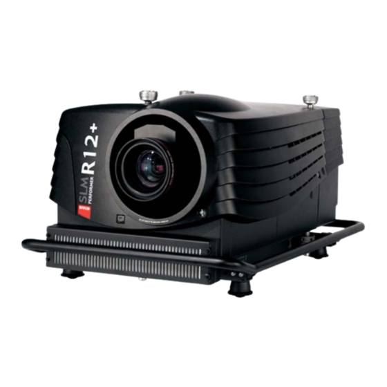
- Page 1 SLM R12+ Performer Service Manual R9010170 R9010171 R5976820/00 08/03/2005...
- Page 2 Barco nv Events Noordlaan 5, B-8520 Kuurne Phone: +32 56.36.89.70 Fax: +32 56.36.88.24 E-mail: events@barco.com Visit us at the web: www.barco.com Printed in Belgium...
-
Page 3: Table Of Contents
Table of contents TABLE OF CONTENTS 1. Safety ........................7 Safety Instructions . - Page 4 Table of contents 11.3.2.2 Analog input and sync processing..................74 11.3.2.3 DVI Input .
- Page 5 Table of contents 20.5 Interconnection Diagram ......................156 21.Pixel Map Processor Module R764115.
- Page 6 Table of contents 27.4.3.2.2 Re-converging Green DMD ..................210 27.4.3.2.3 Readjustment of the plungers .
- Page 7 Table of contents 28.3.2.5 Mounting the removed Stacking interlocks................267 28.3.2.6 Mounting the IR Receiver Unit.
- Page 8 Table of contents R5976820 SLM R12+ PERFORMER 08/03/2005...
-
Page 9: Safety
1. Safety 1. SAFETY 1.1 Safety Instructions ARNING Before Removing/Replacing any projector components, turn off the Main Power Switch and un- plug the Main AC power cable. R5976820 SLM R12+ PERFORMER 08/03/2005... - Page 10 1. Safety Safety Instructions Before returning an instrument to the customer, always make a safety check of the entire instrument, including, but not limited to, the following items: a) Be sure that no built-in protective devices are defective and/or have been defeated during servicing. (1) Protective shields are provided on this chassis to protect both the technician and the customer.
- Page 11 Use of a substitute replacement that does not have the same safety charac- teristics as the recommended replacement part in BARCO service data parts list might create shock, fire, and/or other hazards. Product Safety is under review continuously and new instructions are issued whenever appropriate. For the latest information, always consult the appropriate current BARCO service literature.
- Page 12 1. Safety R5976820 SLM R12+ PERFORMER 08/03/2005...
-
Page 13: General Info Slm R12+ P
2. General Info SLM R12+ P 2. GENERAL INFO SLM R12+ P 2.1 Performances Overview Image 2-1 Performances R5976820 SLM R12+ PERFORMER 08/03/2005... -
Page 14: Specifications
2. General Info SLM R12+ P 2.2 Specifications Overview Image 2-2 Specifications R5976820 SLM R12+ PERFORMER 08/03/2005... -
Page 15: Slm R12+ P - Parts
3. SLM R12+ P - Parts 3. SLM R12+ P - PARTS Spare abbreviation Abbreviation Definition Non repairable Consumable Factory Repairable Locally repairable 3.1 SLM R12+ P - List of Modules Control Panel - Overview modules Art. Number Order Number Description Spare abbreviation R763223... - Page 16 3. SLM R12+ P - Parts Light Engine - Overview Modules Art. Number Description Order Number Spare abbreviation R840527 R840527k Light Engine Complete R764423 DLP 3CH SXGA+ Unit Blue R764596 Formatter FTP* Blue R764422 DLP 3CH SXGA+ Unit Green R764595 Formatter FTP* Green R7644221 DLP 3CH SXGA+ Unit Red...
-
Page 17: Slm R12+ P - List Of Kits
3. SLM R12+ P - Parts 3.2 SLM R12+ P - List of Kits Overview Order Number Description Publication Reference R840527K Light Engine Complete R5976786 x x x x x x x R8454096K* Framed Air Filter (6 pack) R84540924k* Framed Air Filter (24 pack) R9841812 Lamp unit replacement R5976754... - Page 18 3. SLM R12+ P - Parts Overview TLD Lenses Lens Reference Metric formulas (meter) Inch formulas (inch) TLD(0.8:1) PD=0.77xSW+0.05 PD=0.77SW+1.97 TLD(1.2:1) PD=1.11xSW-0.01 PD=1.11xSW-0.39 TLD(1.6–2.0:1) =1.47xSW-0.09 =1.47xSW-3.54 =1.85xSW-0.13 =1.85xSW-5.12 TLD(2.0–2.8:1) =1.85xSW-0.17 =1.85xSW-6.69 =2.62xSW-0.24 =2.62xSW-9.45 TLD(2.8–5.0:1) =2.58xSW-0.16 =2.58xSW-6.30 =4.71xSW-0.38 =4.71xSW-14.96 TLD(5.0–8.0:1) =4.52xSW-0.01 =4.52xSW-0.39 =7.53xSW-0.29 =7.53xSW-11.42...
-
Page 19: Slm R12+ P - Location Of The Modules
4. SLM R12+ P - Location of the modules 4. SLM R12+ P - LOCATION OF THE MODULES Convention - Projector Orientation left rear right front Image 4-1 Projector orientation 4.1 Projector side - Left Identification Image 4-2 Module identification - left side Picture Ref. -
Page 20: Projector Side - Right
4. SLM R12+ P - Location of the modules 4.2 Projector side - Right Identification Image 4-3 Module identification - right side Picture Ref. Art. No Identification Manual page R7633705* Lamp Power Supply R763512 Start pulse Generator R764349 Switch Mode Power Supply * Unit article number exclusive modules R5976820 SLM R12+ PERFORMER 08/03/2005... -
Page 21: Projector - Electronic Box
4. SLM R12+ P - Location of the modules 4.3 Projector - Electronic Box Local Keypad & LCD Display Image 4-4 Local Keypad & LCD Panel Picture Ref. Art. No Identification Manual page R763223 Local key pad R763279 LCD Display R5976820 SLM R12+ PERFORMER 08/03/2005... - Page 22 4. SLM R12+ P - Location of the modules Communication Interface Image 4-5 Communication Interface Art. No Manual page Picture Ref. Identification R763090 Communication Display R763766 Communication Interface SDI Input Image 4-6 SDI Input R5976820 SLM R12+ PERFORMER 08/03/2005...
- Page 23 4. SLM R12+ P - Location of the modules Picture Ref. Art. No Identification Manual page R7632485 SDI Input Input Selector 1/2 & Digital Decoder Image 4-7 Input selector 1/2 Picturer Ref. Art. No Identification Manual page R763826 Digital Decoder R763850 Input Selector 1/2 Input Selector 2/2 &...
- Page 24 4. SLM R12+ P - Location of the modules CPU & Backplane Digital Inputs Image 4-9 CPU & Digital backplane Picture Ref. Art. No Identification Manual page R763378 Digital Backplane R7638857 R5976820 SLM R12+ PERFORMER 08/03/2005...
- Page 25 4. SLM R12+ P - Location of the modules Pixel Map Processor (PMP) Image 4-10 Pixel Map Processor Picture Ref. Art. No Identification Manual page R763348 Pixel Map Processor (PMP) R763850 Input Selector 1/2 R5976820 SLM R12+ PERFORMER 08/03/2005...
- Page 26 4. SLM R12+ P - Location of the modules FIB - Temp & Motor Control - Power Backplane Image 4-11 FIB - Temp & Motor Control - Power Backplane Picture Ref. Art. No Identification Manual page R764346 Formatter Interface board R764203 Temp.
- Page 27 4. SLM R12+ P - Location of the modules IR Receivers & Temperature Sensor Image 4-12 IR receiver Front & Rear - Temp. Sensor Picture Ref. Art. No Identification Manual page R762790 Ambient Temperature Sensor R763261 IR Receiver ’Front’ R763261 IR Receiver ’Rear’...
- Page 28 4. SLM R12+ P - Location of the modules Picture Ref. Art. No Identification Manual page R763512 Start Pulse Generator Complete R7632245s Start Pulse Generator Sub/2 Switch Mode Power Supply Image 4-14 Switch Mode Power Supply Picture Ref. Art. No Identification Manual page R764349...
-
Page 29: Projector - Accessories
4. SLM R12+ P - Location of the modules Tilt Switch & Lamp Info Image 4-15 Tilt switch & Lamp Info Picture Ref. Art. No Identification Manual page R764240 Tilt Switch R763295 Lamp Info 4.4 Projector - Accessories IR Remote Control (RCU RC5) Image 4-16 IR Remote Control (RC5) R5976820 SLM R12+ PERFORMER 08/03/2005... - Page 30 4. SLM R12+ P - Location of the modules Projector Ref. Art. No Identification Manual Ref. R763604 IR Remote Control (RC5) R5976820 SLM R12+ PERFORMER 08/03/2005...
-
Page 31: Slm R12+ P - Location Of The Fans
5. SLM R12+ P - Location of the Fans 5. SLM R12+ P - LOCATION OF THE FANS 5.1 Fans - Mounted on Air Outlet Identification Image 5-1 Fan on Air Outlet Projector Ref. Art. No Identification Manual Ref. B3245651D Fan Air Outlet B3245571D Fan cooling DMD Green... - Page 32 5. SLM R12+ P - Location of the Fans Identification Image 5-3 Cold mirror Fan Projector Ref. Art. No Identification Manual Ref. B3245911D Fan cooling Cold mirror Identification Image 5-4 Fans on front projector Projector Ref. Art. No Identification Manual Ref. B3245311D Fan cooling SMPS B3245311D...
-
Page 33: Fans - Mounted On The Electronic Box
5. SLM R12+ P - Location of the Fans 5.3 Fans - Mounted on the Electronic Box Identification Image 5-5 Fan on Elca Box Projector Ref. Art. No Identification Manual Ref. B3245963D Fan cooling PMP & Lamp Cathode B3245571D Fan cooling DMD Red 5.4 Fans - Mounted on Optical Base Identification Image 5-6... -
Page 34: Fans - Mounted On Light Engine
5. SLM R12+ P - Location of the Fans Identification Image 5-7 Fans-Light Engine outlet Projector Ref. Art. No Identification Manual Ref. B3246261 Light Engine air exhaust 5.5 Fans - Mounted on Light Engine Identification Image 5-8 Fans-Light engine R5976820 SLM R12+ PERFORMER 08/03/2005... -
Page 35: Fans - Mounted On The Lamp Power Supply
5. SLM R12+ P - Location of the Fans Projector Ref. Art. No Identification Manual Ref. B3246261D Fan cooling light engine top (Prism) B324557D Fan cooling DMD Blue 5.6 Fans - Mounted on the Lamp Power Supply Identification Image 5-9 Fans-LPS mounted Projector Ref. - Page 36 5. SLM R12+ P - Location of the Fans R5976820 SLM R12+ PERFORMER 08/03/2005...
-
Page 37: Interconnection Diagram
Block diagram SLM R12+ Performer MOTOR DRIVER KEYPAD FORMATTER LCD panel OPTICAL PROJECTION PIXEL MAP FORMATTER Communication Formatter LENS ENGINE PROCESSOR PROCESSOR Interface INTERFACE FORMATTER Display Input Selection Input Backplane Lamp Formatter Power Module Decoder Fan & Motor Front IR Rear IR Light Lamp... - Page 38 6. Interconnection diagram Interconnection diagram Image 6-2 Interconnection diagram R5976820 SLM R12+ PERFORMER 08/03/2005...
-
Page 39: Ir Transmitter Rc-5 Coded R763569
7. IR Transmitter RC-5 Coded R763569 7. IR TRANSMITTER RC-5 CODED R763569 7.1 General Info View of the Remote Control Image 7-1 IR Remote Control RC5 coded View of the RCU Board Top view Bottom view Image 7-2 RCU board Article No Description Picture Ref. -
Page 40: Access To The Ir Transmitter Board
7. IR Transmitter RC-5 Coded R763569 7.2 Access to the IR Transmitter Board Handle as follows: 1. Remove the screw (1) , using a Torx Screwdriver (T10), holding top and bottom housing together. Image 7-3 Access to IR transmitter board 2. - Page 41 7. IR Transmitter RC-5 Coded R763569 Image 7-5 Battery cover removal 2. Plug in the battery (9 V battery - type E-block or equivalent) onto the battery contact plate (A). Image 7-6 Battery connection 3. Place the battery into the lower compartment (B) (.image 7-6) 4.
-
Page 42: Technical Info
7. IR Transmitter RC-5 Coded R763569 7.4 Technical Info Pin Assignment Micro Contoller Pin functions: RB 0 Row 7 RB 1 Row 6 : Power Supply : Ground connection RB 2 Row 5 Oscillator (osc1, Osc2 Keyboard ): Use of a 864 kHz Ceramic resonator TOCK1 RB 3 Row 4... -
Page 43: Technical Description
7. IR Transmitter RC-5 Coded R763569 Enhancements Enhancements: Jumper W1 'Address Mode' Installed? - Yes: command send with free address - No: command send with fixed address Jumper W2 'Address Entry' Installed? - Yes: entering address with 2 digits (0..31) - No: entering address with 1 digit (0..9) Jumper W3 'Extend' Installed? - Yes: extended... - Page 44 7. IR Transmitter RC-5 Coded R763569 Backlight LED Drive The transistor Q8 drives the 12 LED’s via their ballast resistors R30..R41. The On/Off status is imposed through R22 by IC1, output RA2, which handles the switch-on criteria. When the Jack cable connection is installed, the transistor Q8 is driven by the saturated transistor Q10 through R25, causing the backlight to be lit continuously.
-
Page 45: Local Keypad & Lcd Display
8. Local Keypad & LCD Display 8. LOCAL KEYPAD & LCD DISPLAY 8.1 General Info View of the local keypad & LCD display Image 8-1 Front view Local Keypad & LCD display View of the modules Image 8-2 Picture Ref. Art. -
Page 46: Technical Description
8. Local Keypad & LCD Display Image 8-3 Board removal 2. Remove the 3 screws (C) holding the board onto the front end. 3. Replace the LCD display module. Removal Control Switch module 1. Disconnect the flat cable plug (1) and wired plug (2) from control switch module (image 8-3). 2. - Page 47 8. Local Keypad & LCD Display PIC16C55 Pin functions: Pin functions: Reset In MCLR/VPP VDD: Power Supply Vss: Ground connection Oscillator : Use of a 400kHz Ceramic resonator with 2 o a r load capacitors of 82pF. Osc. In sense MCLR Reset Input : to be activated in 2 cases: inputs - Power On: all memory locations are initialised.
-
Page 48: Status Conditions & Fault Analysis
8. Local Keypad & LCD Display 1. Address key: The ’ADDR’ command is activated along with the ’always listen’ address value (address ’10’). A 5 seconds countdown starts, during which 1 or 2 numeric key entries are expected. Each numeric key entry is followed by a 260 ms hold off and restarts the countdown, but now for 2 seconds. - Page 49 8. Local Keypad & LCD Display Info Display LCD Display Error Description ERROR(-1002) Lamp parameter "maximum power" corrupt or not within range. WRONG LAMP PARAMETER(S) ERROR(-1003) Lamp parameter "minimum power" corrupt or not within range. WRONG LAMP PARAMETER(S) ERROR(-1004) Lamp parameter "minimum power" greater than lamp parameter "maximum power".
- Page 50 8. Local Keypad & LCD Display Info Display LCD Display Error Description ERROR(-2001) Mains voltage lower than minimum specified mains voltage. MAINS VOLTAGE TOO LOW ERROR(-2002) Unable to start the lamp. LAMP START FAILED ERROR(-2003) Mains voltage higher than maximum specified mains voltage. MAINS VOLTAGE TOO HIGH Lamp shut down, unknown error ERROR(-2004)
- Page 51 8. Local Keypad & LCD Display Info Display LCD Display Error Description ERROR(-2404) LPS with I C slave address 0x22: Mains voltage too low; must be >180Vrms. LAMP POWER SUPPLY ERROR(-2424) LPS with I C slave address 0x22: Error in LPS power circuits. LAMP POWER SUPPLY ERROR(-24xx) LPS with I...
- Page 52 8. Local Keypad & LCD Display Info Display LCD Display Error Description ERROR(-2740) LPS with I C slave address 0x28: "Error mains" signal from SMPS module has shut down the LPS module. LAMP POWER SUPPLY ERROR(-2750) LPS with I C slave address 0x28: Over-temperature on heatsink mains rectifier.
- Page 53 8. Local Keypad & LCD Display Info Display LCD Display Error Description ERROR(-3006) The Fan at the cathode of the lamp is not working. CATHODE FAN ERROR ERROR(-3007) The SMPS is in the “In System Programming” mode. SMPS IN ISP MODE ERROR(-4000) Incompatible hardware was found.
-
Page 54: Error List On Info Display Only
8. Local Keypad & LCD Display Info Display LCD Display Error Description ERROR(-4111) Voltage +15V is too low VOLTAGE ERROR ERROR(-4112) Voltage +30V is too low VOLTAGE ERROR ERROR(-4113) Voltage +12V is too low VOLTAGE ERROR Voltage +5V is too low ERROR(-4114) VOLTAGE ERROR ERROR(-4115) - Page 55 8. Local Keypad & LCD Display Info Error Error Description Display "Lamp" ERROR Indicates an error concerning the lamp. This can be: • an error concerning the LPS • an error on the lamp info module If it concerns an error on the lamp info module, "Wrong Lamp Parameter(s) is displayed on the LCD display.
- Page 56 8. Local Keypad & LCD Display R5976820 SLM R12+ PERFORMER 08/03/2005...
-
Page 57: Communication Module R763768
9. Communication Module R763768 9. COMMUNICATION MODULE R763768 9.1 General Info View of the Communication module Image 9-1 Front view Communication module View of the modules Image 9-2 View of the assembly Picture Ref. Article No Identification R763768 Communication Interface complete ( + Display) R763766 Communication main module R763090... -
Page 58: Interconnection With Cpu
9. Communication Module R763768 9.2 Interconnection with CPU Interconnection diagram Network Communication Interface Interface Interface IC6/IC8/ IC1/IC2 IC10/T2 IC9/T1 External IR Front DIMM-PC RS232/422 Interface IR Disable IR/RC5 Q6/Q5/Q11 Interface Q3/Q4 S1/S2 Loop through External (Power Off) IR Rear RS422 Termination IR Disable Q7/Q8... -
Page 59: Technical Description
This unit makes it possible to communicate with the projector. You can interface with the projector in several ways: • Communication port : communication with Barco equipment (RCVDS, … ) • RS232 and RS422 port with active and passive loop through •... - Page 60 9. Communication Module R763768 Remote XLR connection • The direction of communication is determined by the RMT_DIR line. A low puts the interface in receiving mode, a high in transmitting mode. All data is put on the RMT_DATA line. • The TTL level of the data is translated into a differential voltage by I6 and is then superimposed onto the ++24V supply by transformer T1.
-
Page 61: On Board Connector Pin Assignment
9. Communication Module R763768 9.4 On board connector pin assignment Input Connectors Image 9-5 On board connector pin assignment Input Connector J1 - CommunicatioGroundn Port Pin Name Pin No In/out Definition Signal N_PPM/RC5 PPM or RC5 from RCVDS Transmit data from RCVDS RXD/SDA Receive data or I C SDA to RCVDS... - Page 62 9. Communication Module R763768 Input Connector J3 - RS232/422 Out Ground RXD+/DSR Receive data+ / Data Set Ready RS422/232 1,7-9 Not connected Input Connector J4 - IR Jack Pin Name Pin No In/out Definition Signal N_RC5 RC5 input (current driver) INFO_JACK Info on jack present 0/+9V...
- Page 63 9. Communication Module R763768 Interconnection with CPU & Local Keypad Local Keypad J101 J700 J101 J700 J409 J300 Communication Interface Image 9-6 Interconnection with CPU & Local Keypad Connector J101 - from Local Keypad Pin Name Pin No In/out Definition Signal Ground AMB_LIGHT...
- Page 64 9. Communication Module R763768 Connector J700 - Interconnection CPU/Local Keypad SDA_ERROR I2C SDA signal to display SCL_ERROR I2C SCL signal to display SCL_COMM I2C SCL signal to comm port SDA_COMM I2C SDA signal to comm port IR_DISF Disable front IR receiver /PMP_PE Power on signal IR_OK...
- Page 65 9. Communication Module R763768 Interconnection with Input Backplane J409 Input Backplane J101 J700 J409 J300 Communication Interface Image 9-7 Interconnection with Input Backplane Connector J6 - IR Receiver Rear Pin Name Pin No In/out Definition Signal ++5V Power supply IR_REAR RC5 signal from rear IR receiver Ground Connector J6 - IR Receiver Front...
-
Page 66: On Board Information Display
9. Communication Module R763768 Connector J300 - to Display L_PWR_ON Signal for standby led (power on/off) SCL_ERROR I2C SCL signal to error display SDA_ERROR I2C SDA signal to error display IR_DISPLAY RC5 signal from IR receiver on display unit ++5V Power supply Connector J409 - Power Connection Pin Name... -
Page 67: Error List On Info Display Only
9. Communication Module R763768 This unit contains two seven segment led display (E), four normal LEDs (A..D) and an IR receiver (F). The display is used to show the status of the projector for instance the selected input number, error codes, …. The four normal leds each have a specific function: •... - Page 68 9. Communication Module R763768 Info Error Error Description Display Formatter ERROR Indicates an error concerning the formatter. This can be: • No I2C communication (no acknowledge) with the formatter board • Formatter error (see menu "SERVICE/DIAGNOSIS/FORMAT- TER") C Panellink Out No I C communication (no acknowledge) with Panellink Out EEPROM.
-
Page 69: Serial Digital Input Module R7632485
10. Serial Digital Input Module R7632485 10. SERIAL DIGITAL INPUT MODULE R7632485 10.1 General Info View of the SDI Input module Front view Rear view Image 10-1 View SDI input module 10.2 Technical Info Technical description This interface is made for serial digital video (4:2:2) according to SMPTE259 (270Mbit/s). The input signal is amplified (with equalizer) and sampled with a regenerated clock. - Page 70 10. Serial Digital Input Module R7632485 Power Supply Image 10-3 SDI input Power supply The SDI input module receives its power supply via the on board Euro connector which is plugged in onto the Euro connector J1 on the input backplane Connector J1 on Input Backplane Pin C17 Pin C18–C19–C20...
-
Page 71: Signal Input Selection R763850 & R763851
11. Signal Input Selection R763850 & R763851 11. SIGNAL INPUT SELECTION R763850 & R763851 11.1 General Info Introduction The full input section comprises two 5-cable fixed BNC inputs and two digital slots to insert (optional) digital modules like the SDI / H-SDI or another digital decoder. -
Page 72: Block Diagram Signal Input Selection 1 & 2
11. Signal Input Selection R763850 & R763851 11.2 Block Diagram Signal Input Selection 1 & 2 Block diagram Image 11-2 Block diagram Signal Input selection 1& 2 R5976820 SLM R12+ PERFORMER 08/03/2005... -
Page 73: Technical Description Input Selector 1 & 2
11. Signal Input Selection R763850 & R763851 11.3 Technical Description Input Selector 1 & 2 11.3.1 Technical Description Input Selector 1 11.3.1.1 General Description General description The full input section comprises two (-cable fixed BNC inputs and two digital slots to insert (optional) digital modules like the SDI / H-SDI or another digital decoder. -
Page 74: Dvi Input (Sheet 3/11)
11. Signal Input Selection R763850 & R763851 3. Sync clamping-restoration (sheet 1/12). HS/CS and VS sync processing Most of the sync processing, like HS / VS separation is done inside the ADC chip. Hence, the sync signals just need a little restoration prior to enter them into the AD9888. -
Page 75: Dvi Output (See Sheet 3/11)
11. Signal Input Selection R763850 & R763851 Image 11-3 Block diagram AD9888 Output of the ADC is an RGB 48 bit digital signal. Each color is 2x8bit (odd and even). The split in odd and even is done to lower the clock (clock is half by the odd/even split). -
Page 76: Power Section
11. Signal Input Selection R763850 & R763851 • It converts the parallel programming data from the controller into a serial bit stream for the two multiplexing FPGA’s I23/I24. • It allows the controller to set the control signals of the modules Input Selector 1 and Input Selector 2 by writing to certain registers. -
Page 77: Power Supply
11. Signal Input Selection R763850 & R763851 11.4 Power Supply 11.4.1 Power Diagram for Input Selection module 1 Schematic Image 11-4 Power diagram (part 1) R5976820 SLM R12+ PERFORMER 08/03/2005... - Page 78 11. Signal Input Selection R763850 & R763851 Image 11-5 Power diagram (part 2) R5976820 SLM R12+ PERFORMER 08/03/2005...
- Page 79 11. Signal Input Selection R763850 & R763851 Location Components on board J204 J205 J207 J206 J205 J204 J207 J206 A1 +30V A1 GND A1 +3.3VD A2 GND A2 +3.3VD B1 GND B1 +3.3VD B2 GND B2 +3.3VD C1 GND C1 +3.3VD C2 GND C2 +3.3VD D1 ++5V...
-
Page 80: Power Diagram For Input Selection Module 2
11. Signal Input Selection R763850 & R763851 11.4.2 Power Diagram for Input Selection module 2 Schematic Image 11-7 Power diagram R5976820 SLM R12+ PERFORMER 08/03/2005... - Page 81 11. Signal Input Selection R763850 & R763851 Location Components on board J200 22 23 (F1 to F25: GND) GND +3.3VD +3.3VD +3.3VD +3.3VD +5V GND -12V +12V (C1 to C25: GND) J200 Image 11-8 Power supply (location components) R5976820 SLM R12+ PERFORMER 08/03/2005...
- Page 82 11. Signal Input Selection R763850 & R763851 R5976820 SLM R12+ PERFORMER 08/03/2005...
-
Page 83: Digital Decoder R763826
12. Digital Decoder R763826 12. DIGITAL DECODER R763826 12.1 General Info Introduction This decoder board is connected to the Input Selection 1 and 2 boards and accepts video (CVBS), S-video (Y/C) and component signals. These signals are entered via the programmable 5-cable BNC inputs. It is obvious that either a computer RGB signal or a video signal can be selected. -
Page 84: Block Diagram Digital Decoder
SYNC_DEC ANALOG 1 Y/CVBS_DEC ADC 1 COMPONENT PROCESSING Y/CVBS_DEC ANALOG 2 VS_DEC CHROM_DEC HS_DEC ADC 2 CHROMINANCE PROCESSING Y:U:V DEC_OUT (0-7) 4:2:2 DIGITAL PROCESSING COMB FILTER ANALOG 3 BLUE_DEC ADC 3 CLK_DEC LUMINANCE PROCESSING ANALOG 4 RED_DEC ADC 4 CRYSTAL BLOCKDIAGRAM DIGITAL DECODER R763826... -
Page 85: Technical Description
12. Digital Decoder R763826 12.3 Technical Description 12.3.1 General Introduction This decoder board is connected to the Input Selection 1 and 2 boards and accepts video (CVBS), S-video (Y/C) and component signals. These signals are entered via the programmable 5-cable BNC inputs. It is obvious that either a computer RGB signal or a video signal can be selected. -
Page 86: Power Supply
12. Digital Decoder R763826 The colour difference signals are first passing a low-pass filter, and then mutliplexed according the ITU standard. The Y, on the other hand, passes a high pass filter and then a delay compensation. In a last stage, a multiplexer “selects” the decoder output or the R/R-Y, G/Y or B/B-Y matrixed signals. Digital processing - Scaling. -
Page 87: Digital Inputs Backplane R763378
13. Digital Inputs Backplane R763378 13. DIGITAL INPUTS BACKPLANE R763378 13.1 General Info Introduction This module connects Input Selector 2 (R763851) and the two Digital Input slots with Input Selector 1 (R763850). It also gives power to the Controller (R7638858) and the Communication Interface (R763766). It receives the standby I²C signals from the Controller and routes them through Input Selector 1 to the Power Backplane (R764239). - Page 88 13. Digital Inputs Backplane R763378 SDI Input Module Removed Image 13-2 Power Supply Voltage monitoring R5976820 SLM R12+ PERFORMER 08/03/2005...
-
Page 89: Interconnection With Communication Interface
13. Digital Inputs Backplane R763378 13.3 Interconnection with Communication Interface Interconnection diagram Communication Interface R763766 CPU R7638857 CPU R7638856 CPU R7638858 IR Detection from Jack or XLR IR_JACK J700 R10/R11/Q3 18 IRQ_RC5 17 IR_DISR IRQ_RC5 13 IR_DISF IR drive IR XLR J709 Jack select... - Page 90 13. Digital Inputs Backplane R763378 R5976820 SLM R12+ PERFORMER 08/03/2005...
-
Page 91: Power Distribution Backplane R764239
14. Power Distribution Backplane R764239 14. POWER DISTRIBUTION BACKPLANE R764239 14.1 General Info View of the Power Distribution Backplane Power Distribution Backplane R764239 Rear view Front view Image 14-1 View of the Power distribution backplane Short description The Power distribution backplane routes through the different logical signals and provides power to the respective modules ( Mounted in the Electronic Box). -
Page 92: Pin Assignment Connectors On Board
14. Power Distribution Backplane R764239 14.2 Pin Assignment Connectors on Board 14.2.1 Euro-Connectors Euro-Connector Rear Side Backplane J601 J602 SMP Supply R764349 J602 J601 J602 J602 to Backplane to Backplane to Backplane to Backplane FAN_4_CTRL ++5V TILT_SW +12V 3V3_SENSE +15V FAN_3_CTRL +30V NTC_LAMP... -
Page 93: Wire-Connections
14. Power Distribution Backplane R764239 Euro-Connector Front Side Backplane J204 J205 J206 J207 Input Selection 1 R763850 Image 14-3 Interconnection with Input selection 1/2 14.2.2 Wire-Connections Not used wire-connections J415 J411-412-413 not connected not connected not connected not connected not connected Image 14-4 Not used wire-connections 14.2.2.1 Wire-connections to FANs... - Page 94 14. Power Distribution Backplane R764239 Power backplane R764239 J10 J11 J12 from SMPS Image 14-5 Interconnection FAN Group 1 Interconnection FAN Group_2 Color of the wires of the connection cable is Violet/Black R5976820 SLM R12+ PERFORMER 08/03/2005...
- Page 95 14. Power Distribution Backplane R764239 Power backplane R764239 to & from SMPS Image 14-6 Interconnection FAN Group_2 Interconnection FAN Group_3 Color of the wires of the connection cable is Orange/Black R5976820 SLM R12+ PERFORMER 08/03/2005...
- Page 96 14. Power Distribution Backplane R764239 to & from SMPS Not connected Power backplane R764239 Image 14-7 Interconnection FAN Group_3 Interconnection FAN Group_4 Color of the wires of the connection cable is Red. to & from FAN_4_CTRL SMPS Power backplane R764239 Image 14-8 Interconnection FAN Group_4 R5976820 SLM R12+ PERFORMER 08/03/2005...
- Page 97 14. Power Distribution Backplane R764239 Interconnection FAN Group_5 Color of the wires of the connection cable is Blue. Power backplane R764239 TO FAN_5 TO FAN_5 FAN_5 to & from SMPS Image 14-9 Interconnection FAN Group_5 R5976820 SLM R12+ PERFORMER 08/03/2005...
-
Page 98: Wire-Connections To Modules
14. Power Distribution Backplane R764239 14.2.2.2 Wire-connections to Modules Interconnection with Temperature & Motor Control module Temperature & Motor Control R764203 From Backplane (SMPS) From Backplane J504 J520 Power backplane R764239 J904 J920 Image 14-10 Interconnection with Temperature and Motor Control module R5976820 SLM R12+ PERFORMER 08/03/2005... - Page 99 14. Power Distribution Backplane R764239 Interconnection with Formatter Interface module (FIB) Formatter Interface Module R764346 Power backplane R764239 J507 Image 14-11 Interconnection with Formatter Interface module R5976820 SLM R12+ PERFORMER 08/03/2005...
- Page 100 14. Power Distribution Backplane R764239 Interconnection with IR Receivers & Ambient Temp Sensor Ambient Temperature Sensor IR Receiver Rear IR Receiver Front Power backplane R764239 J888 J887 Image 14-12 Interconnection with IR Receivers & Ambient Temp Sensor R5976820 SLM R12+ PERFORMER 08/03/2005...
- Page 101 14. Power Distribution Backplane R764239 Interconnection with Tilt Switch & Lamp Info Tilt Switch Lamp Info Power backplane R764239 Image 14-13 Interconnection with Tilt Switch & Lamp Info R5976820 SLM R12+ PERFORMER 08/03/2005...
- Page 102 14. Power Distribution Backplane R764239 Interconnection with Micro switch, Light Sensor & Lamp Temp NTC Micro Switch Linght Sensor Lamp NTC Power backplane R764239 J416 Image 14-14 Interconnection with Micro switch, Light Sensor & Lamp Temp NTC R5976820 SLM R12+ PERFORMER 08/03/2005...
-
Page 103: Lamp Power Supply R7633705
15. Lamp Power Supply R7633705 15. LAMP POWER SUPPLY R7633705 Attention! WARNING THIS CIRCUIT BOARD IS HOT TO AC. THIS POWER SUPPLY, DOES NOT USE A LINE ISOLATION TRANSFORMER, MEANING A PORTION OF THE CIRCUITRY IS HOT-TO-LINE AND SHOULD BE TREATED WITH CAUTION. Also When the mains is switched off, a period of at least 2 minutes must pass before unplugging the module for servicing... -
Page 104: Technical Info
15. Lamp Power Supply R7633705 Lamp Power Supply Lamp Power Supply disassembled Mechanical parts removed Lamp Power Supply Complete Image 15-3 Modules of the LPS Order Number for the LPS Item Order No R7633705K Lamp Power Supply (Complete) 15.2 Technical Info General This module behaves like an electronic ballast for the lamp of the projector. - Page 105 15. Lamp Power Supply R7633705 General composition The R7633705 is the part number of the complete unit. This unit contains all necessary electronic circuits to work as an independent power supply unit for the Xenon lamp. This includes its own low voltage SMPS for the internal circuits. On exception: the built in microprocessor gets its supply via connector J619 from the external projector SMPS module.
- Page 106 15. Lamp Power Supply R7633705 Red LED: Error Green LED: PFC OK Green LED: LPS OK Green LED: Lamp On Yellow LED: LVPS OK Image 15-4 View operation LEDs LPS Mains Input F100 Bridge Switch Rectifier Filter StdBy Power Supply F200 Low Voltage Rectifier...
-
Page 107: Interconnection Diagrams
15. Lamp Power Supply R7633705 Connectors Primary side J609 Through this connector the module is connected with the SMPS of the projector. The SMPS is supplied with the +380VM output of the PFC. +380VM In standby mode: Rectified mains volatge When PFC is active: +380V DC or +280V DC nominal The output is fused with F340 (1.25A) on the R7632103. - Page 108 15. Lamp Power Supply R7633705 Interconnection LPS & SMPS Switch Mode Power Supply R764349 Lamp Power Supply R7633705 J618 J619 J620 J609 J609 J619 J620 +380VM Image 15-7 Lamp Power Supply Control R5976820 SLM R12+ PERFORMER 08/03/2005...
-
Page 109: Controls On Board
15. Lamp Power Supply R7633705 Boards interconnection LPS-X Processing/5 R7632105 LPS-X In/Out/3 R7632113 J603 J603 J608 J608 J604 J605 J605 J604 primary secondary Power Mosfet Switchers Q550/551 J605 J605 J604 J604 Q560/561 Image 15-8 Boards interconnection 15.4 Controls on Board Lamp Power Supply FAN Control Block diagram R5976820 SLM R12+ PERFORMER 08/03/2005... - Page 110 15. Lamp Power Supply R7633705 LPS Processor Module R7632105 IC212 8-Channel Analogue Multiplexer/ Demultiplexer 8MHz IC214 XTAL1 XTAL2 8-BIT MICRO CONTROLLER P1.0/TXD J603 P1.1/RXD FAN_OK P1.2/SCL/TO P1.3/SDA/INTO P1.4/INT1 P1.5/RST P1.6/PWM1 P1.7/PWM2 FAN_SPD* PWM/CMP2P0.0 PWM0/CIN2B/P0.1 CIN2AP0.2 AD0/CIN1BP0.3 AD1/CIN1AP0.4 AD2/CCMPREFP0.5 AD3/CMP1P0.6 T1/P0.7 * This PWM (Pulse Width Modulated) signal drives the FANs via a PWM converter on the R7632113 module.
- Page 111 15. Lamp Power Supply R7633705 Fan 1 J380 Fan 2 J381 Image 15-10 FAN Connection to board Temperature Sensing on Board Block Diagram R5976820 SLM R12+ PERFORMER 08/03/2005...
- Page 112 15. Lamp Power Supply R7633705 LPS Processor Module R7632105 8MHz IC213 IC214 8-Channel Primary Secondary XTAL1 XTAL2 Analogue 8-BIT MICRO CONTROLLER Multiplexer/ Demultiplexer P1.0/TXD P1.1/RXD P1.2/SCL/TO P1.3/SDA/INTO P1.4/INT1 P1.5/RST P1.6/PWM1 P1.7/PWM2 TEMP_HTSNK_PFC PWM/CMP2/P0.0 PWM0/CIN2B/P0.1 TEMP_TRAFO CIN2A/P0.2 TEMP_HTSNK_LPS AD0/CIN1B/P0.3 AD1/CIN1A/P0.4 TEMP_RECT_SEC AD2/CCMPREF/P0.5 AD3/CMP1/P0.6 T1/P0.7...
-
Page 113: Technical Description Lps-X In/Out R7632113
15. Lamp Power Supply R7633705 Image 15-12 Temperature Sensors location on board 15.5 Technical Description LPS-X In/Out R7632113 15.5.1 General Preview Module R7632113 is part of the complete lamp power supply . Together with the R7632105 (LPS-X PROCESSOR) it delivers the necessary power for the Xenon lamp. -
Page 114: Emc Filter - Rush-In Current Limit - Mains Rectifier
15. Lamp Power Supply R7633705 Low Voltage Power Supply. This power supply (SMPS) generates the stand-by (remains active in the operational mode) voltages for the low power circuits on this module, the boost voltage circuits, and the fans. Lamp Power Supply Secondary. This board contains the transformer T300 of the HF DC/DC CONVERTER. -
Page 115: Secondary Circuit Of The Lps
15. Lamp Power Supply R7633705 Primary ++15VM Voltages • used as feedback information for stabilization of all output voltages. • used in circuits with ”hot ground” on this board and via connector J603 on the other board R7632103. Secondary ++24V mainly used for supplying the two fans. -
Page 116: Boost Up Circuit
15. Lamp Power Supply R7633705 15.5.8 Boost up circuit. Description The ++110V , ++110RET voltage is a floating supply delivered by the on-board SMPS. When the opto-coupler is switched ON by the processor (BOOST_ON) The ++110V voltage charges up the capacitors C309 /C310 via the current source Q363. This current is determined by the zener voltage of Z360, the threshold of Q363 and the source resistors R373+R374. - Page 117 15. Lamp Power Supply R7633705 8 Digital Inputs FAN_OK From the fan drivers on the R7632113 module. Is high when the fans are switched on and will become low when either of the internal fans fails. MAINS_HIGH Is high when the mains input is in the 230V range. PFC_OK Is high when the PFC is switched on and shows no malfunction.
-
Page 118: Power Factor Corrector (Sheet 4/5)
15. Lamp Power Supply R7633705 3 PWM (pulse width modulated) outputs VL_MIN The PWM signal is integrated with R253 and C251 to an analog signal (1 to 5V). This voltage controls the maximum output current of the LPS. With VL_MIN = at low values (depending on the adjusted power) the maximum output current is kept below 110A (hardware current limit in the LPS). - Page 119 15. Lamp Power Supply R7633705 The rectifier bloc on the other board R7632113 is terminated with a small capacitor C400/C401 just to remove the HF components (130khz) generated by the DC / DC converter. The 50 or 60Hz of the mains voltage is not removed by these capacitors and the rectified sinus waveform is presented to the input of the DC/DC converter.
-
Page 120: Primary Lps
15. Lamp Power Supply R7633705 Switching on of Q400-Q401. A short while before Q400-Q401 are driven into conduction, Q403 stops conducting (see timing diagram). Just before Q403 stops conduction, there flows a current in L401/Q403/C404. This current is modulated on the input current flowing through L400/L401/D404 towards the output. - Page 121 15. Lamp Power Supply R7633705 Since X2 = Y2 = 0 the output voltage is: (R261+R262+R260 VS + IS +DIM (R261+R262) VS x IS +DIM The feedback circuit starts regulating from 2.5V onwards (internal reference level of the controller I500). The PS output pin 5 of the analog multiplier must therefore reach 4V (taken into account the divider R263 / P260 / R264).
-
Page 122: Pin Assignment Connectors On Board
15. Lamp Power Supply R7633705 The four FETs form a full bridge. The primary of the transformer (on the other board) is connected at the J605/J604 in series with the blocking capacitors C570, a primary coil L570 and the current transformer. Ringing is limited with the clamper D570/D571. - Page 123 15. Lamp Power Supply R7633705 Connector: J603 Controls Pin Name Pin No Description In/Out Signal 0-5V TRAFO_RANGE Lamp Voltage Range Select 0-5V FAN_SPD Fan Speed control BOOST_ON Boost Enable Voltage 0-5V TEMP_RECT_SEC Temp Sense Heatsink Sec Rectifier 0-5V TEMP_TRAFO Temp Sense LPS Trafo 0-5V Lamp- Voltage Sense Voltage 0-5V...
- Page 124 15. Lamp Power Supply R7633705 Connector: J620 Control Out Pin Name Pin No Description In/Out Signal 0 or 5V NOT_ERROR_M Error signal from SMPS Connectors on LPS In/Out Board R76321113 Connector: J20 Mains 1 (!! Mains Connected !!) Pin Name Pin No In/Out Description...
-
Page 125: Adjustments On Board
15. Lamp Power Supply R7633705 Connector: J603 Controls Pin Name Pin No Description In/Out Signal Secondary Ground Secondary Ground 15.8 Adjustments on Board Location of the Adjustment Controls LPS-X In/Out/3 R7632113 LPS-X Processing/5 R7632105 Lamp Current Sense Adj. PFC Out Sense Adj. Heatsink PFC Temp Sense adj. - Page 126 15. Lamp Power Supply R7633705 R5976820 SLM R12+ PERFORMER 08/03/2005...
-
Page 127: Start Pulse Generator (Spg) R763512
16. Start Pulse Generator (SPG) R763512 16. START PULSE GENERATOR (SPG) R763512 16.1 General Info View of the SPG Start Pulse Generator Complete R763512 Start Pulse Generator Driver R7632245S Image 16-1 View of the SPG Purpose of the SPG The purpose of the Start Pulse Generator (SPG) is to ignite the lamp with a burst of high voltage peaks. The SPG superimposes high voltage peaks onto the normal dc start-up voltage of the lamp supplied by the Lamp Power Supply. -
Page 128: Technical Info
16. Start Pulse Generator (SPG) R763512 16.2 Technical Info Block Diagram Block diagram Start Pulse Generator Lamp Power Supply Xenon Arc Lamp 230VAC 2.2kW Max. 100Vdc output voltage mains Secondary side Superimposing transformer Spark gap Capacitor loading circuit (active during lamp startup) Image 16-2 Block diagram SPG Technical Description... - Page 129 16. Start Pulse Generator (SPG) R763512 Pin assignment connector from LPS Image 16-3 Pin assignment connector J1 Connector: Lamp Power Cables Pin Name Pin No In/Out Description Signal LMP_OUT_POS Positive lamp voltage from LPS Red wire LMP_OUT_NEG Negative lamp voltage from LPS Black wire Connector: J1 SPG Driver Pin Name...
- Page 130 16. Start Pulse Generator (SPG) R763512 R5976820 SLM R12+ PERFORMER 08/03/2005...
-
Page 131: Switch Mode Power Supply (Smps) R764349
17. Switch Mode Power Supply (SMPS) R764349 17. SWITCH MODE POWER SUPPLY (SMPS) R764349 Attention WARNING THIS CIRCUIT BOARD IS HOT TO AC. THIS POWER SUPPLY, DOES NOT USE A LINE ISOLATION TRANSFORMER, MEANING A PORTION OF THE CIRCUITRY IS HOT-TO-LINE AND SHOULD BE TREATED WITH CAUTION. -
Page 132: Technical Description
17. Switch Mode Power Supply (SMPS) R764349 17.2 Technical Description General The following functions are performed by this unit : • Generation of the standby voltages for the controller and the interfacing. • Generation of the “operational voltages” to the rest of the circuits (PMP, Formatter, etc...) •... - Page 133 17. Switch Mode Power Supply (SMPS) R764349 • Measurement of the ambient temperature T_AMB and the lamp house temperature NTC_LAMP. • Switching on and off of the fans and variation of their speed in function of the measured temperature via the different SHDN_xx and VDAC_xx connections.
-
Page 134: Block Diagrams
17. Switch Mode Power Supply (SMPS) R764349 17.3 Block Diagrams SMPS Power diagram Secondary Supply for 2 FANs cooling the SMPs Primary DC/DC Converter FAN_1 I360/Q361/ Q362/Q360 ++5V Switch StandBy VDAC_FAN_1 Q233/Q232 +380VM F100 SMPS I100/T100 ++30V D107 Axial FAN cooling Elca box and Lamp Cathode +30V DC/DC +30V... - Page 135 17. Switch Mode Power Supply (SMPS) R764349 Block Diagram SMPS R764349: Primary Secondary FAN 4 & 5 + TEC Drive/Control FAN located in air outlet channel from LPS PROCESSOR J608 from LPS IN-OUT J609 F300 Flyback Converter FAN_4 F600 I300/T300 400_MAINS-OUT +380VM Mains...
- Page 136 17. Switch Mode Power Supply (SMPS) R764349 SMPS Control diagram a n n e Switch ERROR l ti p l e x e r +5VA l ti p l e m u e x e r Comparator 8 -Bit A/D & D/A converter Voltage N T C...
-
Page 137: Pin Assignment Connectors On Board
17. Switch Mode Power Supply (SMPS) R764349 ERROR SMPS R764349 MicroProcessor Control Diagram/2 J 621 8-BIT ISP_Program ERROR MICRO CONTROLLER High Speed RS-232 line driver/receiver P0.0 P1.0 P0.1 P1.1 P0.2 P1.2 ST B Y P0.3 P1.3 SD A ST B Y J 619 P0.4 _TEC... - Page 138 17. Switch Mode Power Supply (SMPS) R764349 Connector : J619 – to Lamp Power Supply (secondary) Pin Name Pin No Description In/Out Signal ++5V +5V Power Supply StandBy +5VDC Earth (secondary) Serial Clock line 0/5VDC Serial Data line 0/5VDC /ERROR Drops to low level when the NTC sensor in Open Open collector drain collector drain the Lamp house exceeds predefined...
-
Page 139: Status Conditions/Fault Analysis
17. Switch Mode Power Supply (SMPS) R764349 Connector : J601 – to Backplane (secondary) Pin Name Pin No Description In/Out Signal ++30V 30V Standby output +30VDC SHDN_RES c7/c8 Spare output On/Off 0/5VDC FAN_1 Current output to FAN 1 12...28VDC FAN_2 Current output to FAN 2 12...28VDC FAN_3... - Page 140 17. Switch Mode Power Supply (SMPS) R764349 Explanation Green LED D107 Illuminating: indicates the presence of the ++30V Green LED D155 Illuminating: indicates the presence of the +15V Yellow LED D240 Illuminating: indicates the presence of the mains voltage and that the power voltages +3.3V and +5V are within predefined range.
-
Page 141: Temperature & Motor Control Module R764203
18. Temperature & Motor Control Module R764203 18. TEMPERATURE & MOTOR CONTROL MODULE R764203 18.1 Introduction View of the Temperature & Motor Control Module Electronic Box removed Image 18-1 View of the Temperature & Motor Control Module 18.2 Technical Description General This board performs two different functions: •... - Page 142 18. Temperature & Motor Control Module R764203 An 8-bit micro-controller P87LPC768P is slaved to the CPU via an SDAI and SCLI bus. In the event of a cooling problem with heavy risk of damaging the DMD’s, an IRQ_DMD line informs directly the CPU to shut down the projector. Some data are programmable, like start and stop conditions of the DMD cooling, and this data is programmed via the micro-controller into the E²PROM I402 using its own local I²C bus SCL0/SDA0.
- Page 143 18. Temperature & Motor Control Module R764203 HEATSINK T° SENSOR TEC: Thermo-Electric Cooler Image 18-2 DMD temperature control Each DMD is mounted on a metal stud on which there is a TEC , a heatsink and a fan. An NTC-resistor in a voltage-divider circuit gives the temperature on the stud.
- Page 144 18. Temperature & Motor Control Module R764203 DRIVE MTR_SEL Image 18-4 Motor drive Two controlling signals are formed out of a direction signal and a speed signal. The latter is a PWM-signal that can reduce the velocity of the motor by decreasing the duty-cycle. A switch at each end of the run will break the circuit and stop the motor but a diode still enables the reverse direction.
- Page 145 18. Temperature & Motor Control Module R764203 +TEC 8-bit Micro-controller ZOOM Mosfet TEC R FOUS Switcher Multi- Mosfet TEC G Plexer Switcher SHUTTER Mosfet BRIDGE TEC B Switcher I2C Bus FOCUS2 SDA0 I2C interface IC402 LED is ON when cooling is active SCL0 EEPROM microcontroller...
-
Page 146: Pin Assignment Connectors On Board
18. Temperature & Motor Control Module R764203 18.3 Pin Assignment Connectors on Board Indication Connectors on Board J504 J520 Image 18-7 Connectors on board Connectors J25 and J27 are not used. Pin Assignment Connector : J504 From Power distribution backplane Pin Name Pin No In/Out... - Page 147 18. Temperature & Motor Control Module R764203 Connector : J520 From Bckpln Pin Name Pin No Description In/Out Signal Interrupt request IRQ_DMD max. 7A & 12V 400 mA max. I²C Data I²C Clock 100 mA Ground Connector : J10, J13, J16 NTC DMD Red, Green, Blue Pin Name Pin No In/Out...
- Page 148 18. Temperature & Motor Control Module R764203 Connector : J23 Focus Pin Name Pin No Description In/Out Signal CHB1 Encoder Channel 1 Ground Mtr Rev Rev motor terminal Connector : J24 Shift Up/Down Shift Pin Name Pin No In/Out Description Signal DRev Endstop switch reverse direction + diode...
-
Page 149: Formatter Interface Board (Fib) R764346
19. Formatter Interface Board (FIB) R764346 19. FORMATTER INTERFACE BOARD (FIB) R764346 19.1 Introduction View of the Formatter Interface Board Electronic Box removed Formatter Interface Board R764346 Image 19-1 View of the Formatter Interface Board R5976820 SLM R12+ PERFORMER 08/03/2005... -
Page 150: Power Supply
19. Formatter Interface Board (FIB) R764346 19.2 Power Supply From SMPS via Power Distribution Backplane (+5V) Formatter Interface Module R764346 Power backplane R764239 J507 Image 19-2 +5V Power Supply R5976820 SLM R12+ PERFORMER 08/03/2005... - Page 151 19. Formatter Interface Board (FIB) R764346 From SMPS via Pixel Map Processor (+3.3V) Image 19-3 3.3V Power Supply R5976820 SLM R12+ PERFORMER 08/03/2005...
-
Page 152: Light Engine Connection
19. Formatter Interface Board (FIB) R764346 19.3 Light Engine Connection Power Supply to DMD Formatters to Blue Formatter to GREEN Formatter to Red Formatter J301 J303 J302 Image 19-4 Power Supply to DMD Formatters Power Voltage generated on Board On board, 3 LT®1580 7A low dropout regulators are provided to generate the +2.5V for the 3 DMD formatters. The dropout voltage of this device is 100mV at light loads rising to just 540mV at 7A. - Page 153 19. Formatter Interface Board (FIB) R764346 +2.5V RED +2.5V GREEN +2.5V BLUE LED D8 LED D7 LED D6 Front view FIB Rear view FIB Image 19-5 Power Voltage generated on Board R5976820 SLM R12+ PERFORMER 08/03/2005...
- Page 154 19. Formatter Interface Board (FIB) R764346 Signals to DMD Formatters J101 J102 J103 to Red Formatter to GREEN Formatter to Blue Formatter LED indications LED D4 (Green): illuminates as soon as the FPGA I6 is configured. LED D3 (Green): illuminates as soon as the Pixel Clock to the Formatters is OK (=stable).
-
Page 155: Cpu Module R7638858
20. CPU Module R7638858 20. CPU MODULE R7638858 20.1 Introduction View of the module Image 20-1 View of the module R5976820 SLM R12+ PERFORMER 08/03/2005... -
Page 156: Block Diagram Cpu
20. CPU Module R7638858 20.2 Block Diagram CPU Block Diagram Image 20-2 R5976820 SLM R12+ PERFORMER 08/03/2005... -
Page 157: Power Supply On Board
20. CPU Module R7638858 20.3 Power Supply on Board Power Supply IC20 ++3.3V SCL_STBY FET Bus Switches J719 Red LED I2C SMPS Configuration Software SDA_STBY CONF_DONE loaded from IC15 n o t c o n n e c te d P M P ++5V J709... -
Page 158: Interconnection Diagram
20. CPU Module R7638858 20.5 Interconnection Diagram Diagram J702 J703 J703 J702 J709 J700 CPU R7638858 Pixel Map Processor R764115 J700 J409 Communication Interface R763766 1 ++5V J709 J409 2 IR_Rear 3 GND Digital Input Backplane R763378 1 ++5V 2 IR_Front 3 GND J409 1 ++5V... -
Page 159: Pixel Map Processor Module R764115
21. Pixel Map Processor Module R764115 21. PIXEL MAP PROCESSOR MODULE R764115 21.1 View of the PMP Module Location of the PMP Rear Electronic Box Image 21-1 Location of the PMP Module R5976820 SLM R12+ PERFORMER 08/03/2005... -
Page 160: Block Diagram Pmp
21. Pixel Map Processor Module R764115 21.2 Block Diagram PMP Block diagram Image 21-2 Block diagram PMP R5976820 SLM R12+ PERFORMER 08/03/2005... -
Page 161: Short Technical Description
21. Pixel Map Processor Module R764115 21.3 Short Technical Description Data Path Digital RGB data coming form input selector 1 enters the PMP where the data is stored in an SDRAM frame memory. Therefore an SDRAM controller is needed and this controller is implemented in a Xilinx programmable component. Also, the horizontal conversion to the native resolution is done in this component. - Page 162 21. Pixel Map Processor Module R764115 Diagram Power Supply Image 21-4 Diagram Power Supply Component location on board L650 L600 +2.5V L650 +1.8V Image 21-5 Component location on board/1 R5976820 SLM R12+ PERFORMER 08/03/2005...
-
Page 163: Status Conditions / Fault Analysis
21. Pixel Map Processor Module R764115 D652 Q650 Q652 IC650 D602 Q602 Q603 Status Condition PMP Q600 Q601 Image 21-6 Component location on board/2 21.5 Status Conditions / Fault Analysis Introduction The load condition of the programmable logic’s is indicated by means of a Red LED, linked to the respective logic IC. Non lightning of a LED indicates correct loaded IC. - Page 164 21. Pixel Map Processor Module R764115 LED Ref. IC Ref. Descriprion D300 Xilinx IC305 LED On: Xilinx configured D400 XilinxIC400 LED On: Xilinx configured D500 Altera IC500 LED On: Altera configured R5976820 SLM R12+ PERFORMER 08/03/2005...
-
Page 165: Infra Red Receiver Module R763261
22. Infra Red Receiver Module R763261 22. INFRA RED RECEIVER MODULE R763261 22.1 View of the Infra Red Receiver Location of the module Projector Rear View Projector Front View Image 22-1 Location of the IR Receiver module 22.2 Block Diagram IR Receiver Block Diagram IR Receiver IR Transmitter... -
Page 166: Interconnection Diagram
22. Infra Red Receiver Module R763261 22.3 Interconnection Diagram IR module connection to Power Backplane IR Receiver IR Receiver Front Rear Power Backplane R764239 J888 J887 IR Rear IR Front J207 J204 J205 J206 J207 B2 IR_FRONT C2 IR_REAR J204 J205 J206 J207... - Page 167 22. Infra Red Receiver Module R763261 IR signal flow to CPU Communication Interface R763766 CPU R7638857 CPU R7638856 CPU R7638858 IR Detection from Jack or XLR IR_JACK J700 R10/R11/Q3 18 IRQ_RC5 17 IR_DISR IRQ_RC5 13 IR_DISF IR drive IR XLR J709 Jack select...
- Page 168 22. Infra Red Receiver Module R763261 R5976820 SLM R12+ PERFORMER 08/03/2005...
-
Page 169: Ambient Temperature Sensor R762790
23. Ambient Temperature Sensor R762790 23. AMBIENT TEMPERATURE SENSOR R762790 23.1 View of the Ambient Temperature Sensor Location of the module Image 23-1 Location of the module R5976820 SLM R12+ PERFORMER 08/03/2005... -
Page 170: Interconnection Diagram
23. Ambient Temperature Sensor R762790 23.2 Interconnection Diagram Interconnection with SMPS Temperature Sensor R767290 Temp. Sensor Non-inverting LM45 Amplifier 1 ++12V 2 T_AMB_IN 3 GND Power Backplane R764239 J602 J204 J205 J206 J207 J602 C5 ++12V B6 T_AMB_IN J602 8-Bit A/D & D/A converter Voltage NTC_LAMP... -
Page 171: Projector Tilt Switch R764240
24. Projector Tilt Switch R764240 24. PROJECTOR TILT SWITCH R764240 24.1 View of the projector Tilt Switch Location of the module View inside lamp house Image 24-1 Location of the tilt switch module 24.2 Projector Tilting Protection Explanatory Drawing In a projector mounting configuration where tilting of the projector is required, pay attention to the followings mountings rules to maintain maximum performances of the Xenon lamp: •... - Page 172 24. Projector Tilt Switch R764240 Projection Axis Point of Gravity Projection Axis Lamp Axis 15 ° FRONT VIEW 15° Lamp Axis 195° 195 ° Image 24-2 Projector tilting range R5976820 SLM R12+ PERFORMER 08/03/2005...
-
Page 173: Interconnection Diagram
24. Projector Tilt Switch R764240 24.3 Interconnection Diagram Interconnection with SMPS Tilt Switch R764240 EEPROM 1 TILT_SW 2 ++5V 3 SCL_TILT 4 SDA_TILT 5 GND Power Backplane R764239 1 TILT_SW 2 ++5V 4-Channel 3 SCL_TILT I2C Switch 4 SDA_TILT 5 GND SDA_TILT SCL_TILT SDA_STBY... - Page 174 24. Projector Tilt Switch R764240 R5976820 SLM R12+ PERFORMER 08/03/2005...
-
Page 175: Light Output Sensor R763294
25. Light Output Sensor R763294 25. LIGHT OUTPUT SENSOR R763294 25.1 View of the Light Output Sensor Location of the module Light Sensor Upper side Under side Image 25-1 Location of the module 25.2 Technical Info Block diagram Light Sensor Light Sensor R763294 Microcontroller Progr. - Page 176 25. Light Output Sensor R763294 The microcontroller IC I1 execute a frequency measurement and will spread it out over a longer period. On the basis of reference measurement, stored in de EEPROM IC2, the number of corresponding centrum-lumens are calculated. R5976820 SLM R12+ PERFORMER 08/03/2005...
-
Page 177: Interconnection With Cpu
25. Light Output Sensor R763294 25.3 Interconnection with CPU Interconnection diagram Light Sensor R763294 Microcontroller Progr. Light-to-Frequency converter TXD/P1.0 Light Current-to- RXD/P1.1 Photodiode frequency T1/P0.7 converter SCL/TO/P1.2 SDA/INTO/P1.3 CM2/P0.0 EEPROM CIN2A/P0.2 SENS CM1/P0.6 FREQ. 1 ++5V 2 SDA_STBY 3 SCL_STBY Light Sense 4 GND k p l... - Page 178 25. Light Output Sensor R763294 R5976820 SLM R12+ PERFORMER 08/03/2005...
-
Page 179: Lamp Info Module R763295
26. Lamp Info Module R763295 26. LAMP INFO MODULE R763295 26.1 View of the Lamp Info Location of the module View inside lamp house Image 26-1 Location of the module R5976820 SLM R12+ PERFORMER 08/03/2005... -
Page 180: Interconnection Diagram
26. Lamp Info Module R763295 26.2 Interconnection Diagram Diagram Lamp Info R763295 EEPROM 1 ++5V 2 GND 3 SCL_LIM 4 SDA_LIM 8 WP Power Backplane R764239 SDA_LIM SDA_TILT SDA_MTR Lamp Info SDA_SPARE SCL_LIM SCL_TILT SCL_MTR SCL_SPARE ++5V SCL_STBY ++5V Switch Control Logic SDA_STBY J207 ++5V... -
Page 181: Technical Info
26. Lamp Info Module R763295 26.3 Technical Info Description EEPROM X24C16A The EEPROM provides 16384 bits of serial electrically erasable and programmable read-only memory (EEPROM) organized as 2048 words of 8 bits each. Pin Configurations Pin Name Function Pin Description A0 - A2 Address Inputs The X24C16A does not use the device address pins. - Page 182 26. Lamp Info Module R763295 R5976820 SLM R12+ PERFORMER 08/03/2005...
-
Page 183: Maintenance
27. Maintenance 27. MAINTENANCE 27.1 Lens Block 27.1.1 Overview of Micro Switches and Motors Overview Motor End course Switch Left Motor End course Switch Top Up/Down control (B372218) Shutter (B372218) (R3221102D) (B4400011D) End course Switch Down (B372218) Motor End course Switch Right Left/Right control (B372218) (R3221101D) - Page 184 27. Maintenance Image 27-2 Removal front plate lens block 2. Remove the lens holder front plate from the fixation bolts. 3. Remove the 4 springs (A) and the 3 washers (D) from the fixation bolts (to be reused when reassembling) Tilting the Lens block X-Y Plate 1.
-
Page 185: Disassembling A Motor Unit
27. Maintenance Image 27-4 Loosening motor axle block 4. Lift up the lens block X-Y plate (E) to access the motor units Left/Right (F) and the end course micro switches Left/Right (G). Image 27-5 Opening lens block 27.1.3 Disassembling a Motor Unit Motor Unit Up/Down 1. - Page 186 27. Maintenance Image 27-6 Removal motor Up/Down shift 2. Remove the screw (B), accessible through a hole (C) on top of the mechanical frame, fastening the copper motor support (C) onto the lens block. R5976820 SLM R12+ PERFORMER 08/03/2005...
- Page 187 27. Maintenance 3. Remove the motor unit for replacement. Caution: When fixating the copper motor support onto a new motor, be careful not to turn the 2 fixation screws deeper than the thickness of the motor reduction unit. Image 27-7 Mounting motor copper support Motor Unit Left/Right 1.
-
Page 188: Cleaning/Replacement Of The Dust Filters
27. Maintenance Image 27-8 Removal motor Left/Right shift 2. Remove the 2 screws (B) fastening the copper motor support (C) onto the lens block (D). 3. Remove the motor for replacement. Caution: When fixating the copper motor support onto a new motor, be careful not to turn the 2 fixation screws deeper than the thickness of the motor reduction unit (Illustration: see Motor unit Up/Down). -
Page 189: Location Of The Dust Filters
27. Maintenance 27.2.1 Location of the Dust Filters Where mounted? To protect the projector against internal contamination due to forced air cooling, dust filters are mounted at the air inlet of the projector. Therefore 2 casings are mounted on the projector, one on the front (a) and the other on the rear (B), containing an air filter. Image 27-9 Location of the dust filters Dust filter at the front side of the projector... -
Page 190: Dust Filters On The Rear Side Of The Projector
27. Maintenance The dust filter is released and can be removed (C) for cleaning or replacement. Image 27-11 Removing dust filter from its casing How to clean! 1. Put the dirty air filter far away from the projector or preferable in another room. 2. - Page 191 27. Maintenance Image 27-13 Projector rear cover removal 2. Remove the rear cover from projector. Removal of the Air filters 1. Loosen the 6 hexagon socket screws (B) , securing metal fixation plate (A) to rear cover. Image 27-14 Removal metal fixation plate 2.
- Page 192 27. Maintenance 6. Remove metal fixation bar from rear cover. Both air filters (E) can be removed for cleaning or replacement. Image 27-16 Air filter removal How to clean! 1. Put the dirty air filter far away from the projector or preferable in another room. 2.
-
Page 193: Lamp Replacement
27.3.1.2 Product care Installation Kit The universal lamp replacement Kit R9841810 is designed for use ONLY with the BARCO SLM G8/R8, G10/R10, R9+ and R12+ series projectors. Replacement parts When replacement parts are required, be sure the service technician has used original Barco replacement parts or authorized re- placement parts which have the same characteristics as the Barco original part. -
Page 194: Introduction
27. Maintenance 27.3.2 Introduction 27.3.2.1 Content of the kit Content of the kit The lamp kit consists in a lamp housing, Xenon lamp included. That means that the lamp position is factory calibrated following the X- ,Y- and Z-axis. When observing a decrease in light output during the run time of the lamp, ONLY a realignment following the Z-axis can solve the light output decrease. -
Page 195: Removing The Lamp Unit
27. Maintenance Image 27-21 Unlocking the side cover 2. Pull the right side of the panel towards you and next to the right to remove. Image 27-22 Lamp cover removal 27.3.3.2 Removing the Lamp Unit. What has to be done The lamp unit has to be slid out of the projector frame. -
Page 196: Inserting The New Lamp Unit
27. Maintenance Image 27-23 Loosening the spacer screws 2. Using the provided handle (B), pull the lamp unit out of the projector frame. Image 27-24 Sliding out the lamp housing Caution: Be careful not to drop the lamp unit (see safety instructions in front of instruction manual) 27.3.4 Inserting the new lamp Unit 27.3.4.1 Installation of the new Lamp Unit. - Page 197 27. Maintenance Image 27-25 2. Line up the lamp unit guides (A) with the guides on the projector base (B) and push the unit into the frame until it fits. Image 27-26 Lamp unit mounting 3. Secure the position of the lamp unit with the 3 spacer screws. R5976820 SLM R12+ PERFORMER 08/03/2005...
-
Page 198: Optical Alignment Of The Lamp
27. Maintenance Image 27-27 Lamp unit fixation 27.3.4.2 Optical Alignment of the lamp What may be adjusted!! The adjustments to the Y-axis and X-axis (balancing the light intensity) are FACTORY PREADJUSTED. Consequently, both ad- justable screws are anchored by a lock screw and sealed with a warranty label (Destroying the label void the warranty). ONLY the Optical readjustment to the Z-axis may be done and is recommended after the lamp has operated for many run times. -
Page 199: Reinstalling The Side Panel
27. Maintenance 4. Enter the ‘SERVICE MODE’ and select ‘Add-Ins’. Finally set CLO on ‘INACTIVE’. 5. Loosen the lock nut (A), securing the adjustable screw (B) for the optical Z-axis adjustment. Image 27-29 Optical alignment Z-axis 6. Carefully adjust the adjustable screw (B), using an Allen key of 3mm, for maximum light fall on the screen. 7. -
Page 200: Re-Convergence
27. Maintenance Image 27-32 Locking side panel 27.4 Re-convergence 27.4.1 Re-Convergence Kit Overview • Purpose of the kit • Contents of the Kit • Relevant Test Pattern 27.4.1.1 Purpose of the kit Objective To limit the return of light engines for small convergence drifts, a kit has been developed for the qualified technician to allow re-con- vergence the light engine. -
Page 201: Relevant Test Pattern
27. Maintenance R847196 R821751 2x R847204 R847203 R847205 Image 27-33 Contents of the kit 27.4.1.3 Relevant Test Pattern Display test pattern 1. Press the “*” button on the Remote Control to enter the ’Lens adjustment Zoom/Focus’ mode. The lens focus test pattern is displayed with on screen the lens adjustment Zoom/Focus menu. More test patterns are available. 2. -
Page 202: Access To Light Engine
27. Maintenance 27.4.2.1 Access to Light Engine What to do to access the Light Engine • Removal of the Input Panel box (4 screws to loosen). • Removal of the back cover (2 spring screws to loosen). • Removal of the top cover (4 spring screws to loosen and to disconnect the lens dust cloth). Overview •... -
Page 203: Removing The Top Cover
27. Maintenance 27.4.2.1.3 Removing the top cover Removal of the stacking points 1. Loosen the fixation bolt of the 3 stacking points on top of the projector, using an Allen key of 8 mm. Image 27-38 Removal of the stacking points 2. -
Page 204: Disconnection Fans On Light Engine
27. Maintenance to Open to Lock Image 27-40 Removal Lens and dust cloth The lens lock is unlocked and the lens can be removed from lens block. 2. Disconnect the dust protection cloth ring from lens block by pulling the ring backwards (picture B). Removal of the top cover 1. -
Page 205: Removing The Engine Cooling Fan
27. Maintenance Image 27-42 Removal of the Prism cooling fan 2. Take away the Fan from light engine. 27.4.2.2.2 Removing the Engine Cooling Fan Removal To access the adjustable screws of the Green and the Blue DMD panel, the engine cooling fan has to be removed 1. -
Page 206: Temporarily Replacement Of The Air Channel
27. Maintenance Image 27-44 Removal input panel 2. Keep the input panel by the provided handles and pull it backwards to remove. Now, the backplane (board at he bottom) is accessible on which the cable plug of the mentioned Fans are plugged in. 3. -
Page 207: Removal Of The Air Channel
27. Maintenance 27.4.2.3.1 Removal of the Air Channel Necessary tools • Flat blade screwdriver of 5 mm • Torx® driver TX10 • Crosshead screwdriver (medium) How to remove the air channel 1. Remove the ten Torx® TX10 screws (A) on top of the air channel unit. B (x2) A (x10) Image 27-46... -
Page 208: Installation Of The Service Air Channel (Part Of The Kit)
27. Maintenance Image 27-48 Disconnection Fans and GND 6. Remove the two Torx® screws (1&2) fixating air channel unit to starter unit and remove the bolt (3) fixating air channel unit to the optical base. Image 27-49 Disconnection air channel 7. -
Page 209: Re-Convergence The Light Engine
27. Maintenance Image 27-50 Installation service air channel 2. Reconnect (1) the air channel Fan (image 27-50). 27.4.3 Re-convergence the Light Engine 27.4.3.1 Action of the convergence controls Influence of the controls on the convergences The DMD assemblies are provided with 3 adjustable screws. The assembly itself is kept in place by a plunger near the adjustable screw. - Page 210 27. Maintenance Image 27-51 Influence of the controls on the convergences Adjusting the control(s): • (2): Move the respective convergence pattern up or downwards 45° diagonally (Top-Left/Bottom-Right). • (1) & (2) simultaneously: Move the respective convergence pattern up or downwards -45° diagonally (Top-Right/Bottom-Left). •...
-
Page 211: Re-Convergence Green On Red
27. Maintenance 27.4.3.2 Re-convergence GREEN on RED 27.4.3.2.1 Location of controls Location of the lock-down screws Image 27-52 Location of the lock-down screws for the green DMD assembly Location of the convergence adjustable screws Lens Lens Image 27-53 Location of the convergence adjustable screws R5976820 SLM R12+ PERFORMER 08/03/2005... -
Page 212: Re-Converging Green Dmd
27. Maintenance 27.4.3.2.2 Re-converging Green DMD AUTION Be cautious when adjusting the convergence controls, because a small turn causes already many pixel shift. Needed tools R847204 R847204 R847205 R847203 Image 27-54 Needed tools for r-convergence For older versions of the light engine, the screwdriver R847204 is used as well for the convergence adjustable screws as well for the plungers. -
Page 213: Readjustment Of The Plungers
27. Maintenance Gb1 adjustment Gb2+Gb2 adjustment Gb2 or Gb2 adjustment Gb3: top image Gb2: bottom image Image 27-56 Green convergence adjustment 4. Continue with re-convergence in center at the Top and the Bottom of the image as follows (using tool R847204): Adjust the control Gb3 for coincidence of the diagonal Green line of the Green convergence pattern with the Red line of the Red convergence pattern in the center at the top of the image. - Page 214 27. Maintenance Image 27-57 Readjustment plunger 2. Continue with the fine convergence adjustment Convergence screw sense no resistance 1. Turn the plunger clockwise until resistance is sensed again. Image 27-58 Readjustment plunger 2. Continue with the fine convergence adjustment R5976820 SLM R12+ PERFORMER 08/03/2005...
-
Page 215: Re-Convergence Blue On Red
27. Maintenance 27.4.3.3 Re-convergence BLUE on RED 27.4.3.3.1 Location of controls Location of the lock-down screws Image 27-59 Location of the lock-down screws for the blue DMD assembly R5976820 SLM R12+ PERFORMER 08/03/2005... -
Page 216: Re-Converging Blue Dmd
27. Maintenance Location of the convergence adjustable screws Lens Lens Lens Image 27-60 Location of the convergence adjustable screws 27.4.3.3.2 Re-converging Blue DMD AUTION Be cautious when adjusting the convergence controls, because a small turn causes already many pixel shift. Needed tools R847204 R847204... - Page 217 27. Maintenance For older versions of the light engine, the screwdriver R847204 is used as well for the convergence adjustable screws as well for the plungers. How to re-convergence 1. Put the square drive socket (A), with soldered hexagon key, onto a ratchet (B). Image 27-62 2.
-
Page 218: Readjustment Of The Plungers
27. Maintenance Bb1 adjustment Bb2+Bb3 adjustment Bb2 or Bb3 adjustment Bb3: top image Bb2: bottom image Image 27-63 Blue convergence adjustment 4. Continue with re-converging the center at the Top and the Bottom of the image as follows (using tool R847204): Adjust the control Bb3 for coincidence of the diagonal Blue line of the Blue convergence pattern with the Red line of the Red convergence pattern in the center at the top of the image. -
Page 219: Engine Replacement
27. Maintenance Convergence screw is end of course 1. Convergence screw is end of course Image 27-64 Readjustment plunger 2. Continue with the fine convergence adjustment Convergence screw sense no resistance 1. Turn the plunger clockwise until resistance is sensed again. Image 27-65 Readjustment plunger 2. -
Page 220: Access To Image Processor Unit
27. Maintenance Product care Installation kit. The kit R840527K is designed for use ONLY with the Barco SLM 12+ and 9+ series projectors. Replacement parts. When replacement parts are required, be sure the service technician has used original Barco replacement parts or authorized replacement parts which have the same characteristics as the Barco original part. -
Page 221: Removal Of The
27. Maintenance Image 27-67 Pull and remove the side cover 27.5.2.3 Removal of the Back Cover How to remove 1. See "Removing the Back Cover", page 200 27.5.2.4 Removing the Lens When to perform this procedure? The lens needs to be removed when removing the covers from the projector. How to remove the Lens? 1. -
Page 222: Removal Of The Top Cover
27. Maintenance 27.5.2.5 Removal of the Top Cover How to remove 1. See "Removing the top cover", page 201 27.5.2.6 Removal of the lamp unit How to remove 1. See "Removing the Lamp Unit.", page 193 27.5.2.7 Removing the SM Power Supply Module What has to be done ? The cover doors must be removed first. - Page 223 27. Maintenance Image 27-71 Unlock lock screw 4. Turn the metal cover door to the right and remove. Image 27-72 Remove metal cover door Removing the SMPS module 1. Pull the 3 plugs (A, B and C) out of their respective socket. R5976820 SLM R12+ PERFORMER 08/03/2005...
-
Page 224: Removal Of The Air Channel
27. Maintenance Image 27-73 2. Unlock the 2 module locks 3. Slide the module out the projector frame. 27.5.2.8 Removal of the Air Channel How to remove 1. See "Removal of the Air Channel", page 205 27.5.3 Removing the Engine 27.5.3.1 Overview connections behind input box Overview Image 27-74... -
Page 225: Disconnecting The Formatter And Dmd Connections
27. Maintenance 27.5.3.2 Disconnecting the formatter and DMD connections Necessary tools • Torx® driver TX10 • Pair of wire-cutters Disconnect the formatter power connections 1. Turn out both screws (1) fixing the ground leads of the formatter supply cables to the formatter interface board. Image 27-75 Formatter supply connections 2. - Page 226 27. Maintenance green formatter signal connector blue formatter signal connector red formatter signal connector 3. Pull the wires through the opening on top of the formatter board. Temperature sensor and Peltier elements disconnection 1. Pull out the temperature connectors 1, 2 and 3. Image 27-77 Temperature and Peltier connection blue temperature sensor connector...
-
Page 227: Removing The Disconnected Cables
27. Maintenance Image 27-78 Core tube removal 4. Turn out the screw holding the cable support to the right lower corner of the temperature and motor control board. Image 27-79 Cable support removal 27.5.3.3 Removing the disconnected cables How to remove ? 1. -
Page 228: Disconnect The Lens Sensor Cable
27. Maintenance Image 27-80 Cable pass through 27.5.3.4 Disconnect the lens sensor cable How to disconnect ? 1. Disconnect the lens sensor cable through the lens holder gap. Image 27-81 Lens sensor cable disconnection 27.5.3.5 Disconnect the shutter How to disconnect ? 1. -
Page 229: Disconnect The Lens Holder Ground Leads
27. Maintenance Image 27-82 Shutter cable disconnection 27.5.3.6 Disconnect the lens holder ground leads Necessary tools Torx® driver TX10 How to disconnect ? 1. Turn out the screw on top of the lens holder mechanism. Image 27-83 Lens holder ground leads disconnection The 3 ground leads are now free. -
Page 230: Removing The Engine
27. Maintenance Image 27-84 Red DMD fan dicsonnection 2. Unplug the black connector. The supply wires are black and orange. How to disconnect the prism fan ? 1. Cut the white wire tire. Image 27-85 Prism fan disconnection 2. Disconnect the black connector. The supply wires are black and purple. - Page 231 27. Maintenance Image 27-86 Upper fixation bolts engine Image 27-87 Upper fixation bolts engine, bottom view 2. Turn out the lower fixation bolt through the hole in the upper side of the SMPS cabinet. The bolt is mounted under approximately 45 degrees.
-
Page 232: Installing A New Engine
27. Maintenance Image 27-88 Lower fixation bolt engine 3. Lift out the engine. Image 27-89 Lifting up the engine 27.5.4 Installing a new engine 27.5.4.1 Mounting the engine Necessary tools Hex ball head screwdriver 3mm How to mount ? 1. Carefully inset the engine into the projector in such a way that the pins (A) on the optical base matches the center holes (B) in the positioning plate of the engine. - Page 233 27. Maintenance Image 27-90 Positioning pins on optical base Image 27-91 Positioning holes on engine 2. Turn in both upper fixation bolts. R5976820 SLM R12+ PERFORMER 08/03/2005...
-
Page 234: Guiding The Cables
27. Maintenance Image 27-92 Upper fixation bolts 3. Insert the lower fixation bolt through the gap in the upper plate of the SMPS cabinet. Image 27-93 27.5.4.2 Guiding the cables How to guide the wires ? 1. Push the small colored wires for temperature sensing and Peltier cooling through the gap. R5976820 SLM R12+ PERFORMER 08/03/2005... -
Page 235: Connecting The Engine Fans
27. Maintenance Image 27-94 Cable gap in optical base 2. Push the long black wires (power supply wires) of engine through the same gap. 3. Pull the wires through gap A and push them one for one through the pass-through (B) in the side plate of the input panel. Image 27-95 27.5.4.3 Connecting the engine fans Necessary tools... - Page 236 27. Maintenance Image 27-96 Formatter signal connection green formatter signal connector blue formatter signal connector red formatter signal connector 3. Take the eyes of the green and the blue ground lead together, insert a Torx® screw and fixate it to the left fixation hole (left 5). 4.
- Page 237 27. Maintenance 3. Pull all wires of the Peltier elements and the temperature sensor into the black cable holder. Insert a Torx® screw and fixate to the right lower fixation point of the temperature and motor control board. Image 27-98 Cable fixation Mounting the core tube 1.
-
Page 238: Mounting The Lens Holder Ground Leads
27. Maintenance Image 27-100 Formatter power cables green formatter power connector blue formatter power connector red formatter power connector 2. Take the green ground lead, insert a Torx® screw and fixate into left fixation hole of the formatter interface board (1 left). 3. -
Page 239: Connecting The Shutter
27. Maintenance Image 27-102 Lens holder ground leads 27.5.4.5 Connecting the shutter How to connect ? 1. Take the shutter cable (orange - yellow wires) on top of the shutter and connect with the shutter extension cable. Image 27-103 Shutter cable connection 27.5.4.6 Connecting the lens sensor How to connect ? 1. -
Page 240: Re-Assembling The Projector
27. Maintenance Image 27-104 Lens sensor cable 27.5.5 Re-assembling the projector 27.5.5.1 Mounting the Air channel How to mount ? 1. Place the air channel in the projector with the fan to the engine. 2. Insert the two Torx® screws (1&2) fixating air channel unit to starter unit and turn in the bolt (3) fixating air channel unit to the optical base. -
Page 241: Removing The Sm Power Supply Module
27. Maintenance B (x2) A (x10) Image 27-107 Assemble air channel 5. Insert the two bolts (B) fixating the air channel unit to the lamp power supply house (image 27-107). 6. Connect onto the air channel the 3 engine ground leads by turning in the respective fixation screw (image 27-108). (1) Ground connection top air channel (2) Ground connection top air channel (2) Ground connection side air channel... - Page 242 27. Maintenance Image 27-109 Mounting the SMPS module 3. Push the module completely in and close the locks. Closing the SMPS cover 1. Hook the metal cover door on the right side (A) and turn in to the projector (B). Image 27-110 Mounting the metal cover 2.
-
Page 243: Installation Of The Lamp Unit
27. Maintenance Image 27-111 Unlock lock screw 3. Place the side panel on its place. 4. Turn in the screw (A) of the plastic cover door. Image 27-112 SMPS cover door screw 27.5.5.3 Installation of the Lamp Unit. Necessary tools Flatblade screwdriver of 5mm or Nut driver 8mm Installing the lamp unit 1. -
Page 244: Mounting The Top Cover
27. Maintenance Image 27-113 Inserting the lamp 2. Secure the position of the lamp unit with the 3 spacer screws. Image 27-114 Securing the lamp 27.5.5.4 Mounting the top cover Mounting the top cover 1. Place the top cover on the projector. Close the top cover fixation spring screws 1. -
Page 245: Reinstalling The Side Panel
27. Maintenance Image 27-115 Top cover fixation spring screws loosening 2. Fasten 1 spring screws (2), holding side of top cover to projector main frame. 3. Fasten 2 spring screws (3 & 4), holding front of top cover to projector main frame. Mounting the stacking points 1. -
Page 246: Lens Installation
27. Maintenance Reinstalling the side panel 1. Move the cover guides under the back cover and push the front of the cover against the projector frame lining up the cover lock screw with the speed nut (A) on the frame. Image 27-117 Mounting the side cover 2. -
Page 247: Mounting The
27. Maintenance Image 27-119 Mounted Lens 27.5.5.7 Mounting the back cover How to mount ? 1. Slide the back cover over the rear of the projector. Image 27-120 2. Turn with a screwdriver the 3 quarter turn fasteners a quarter turn clockwise (A). 27.5.5.8 Inserting the Input panel How to mount ? 1. -
Page 248: Replacement Of The Light Integration Rod
27. Maintenance Image 27-121 2. Secure the 4 spring screws (B), holding Input Panel Box to projector main frame. 27.6 Replacement of the Light Integration Rod Overview • General Info • Replacement procedure • Alignment of the Light Integration Rod 27.6.1 General Info View of the Light Integration Rod Image 27-122... -
Page 249: Replacement Procedure
27. Maintenance 27.6.2 Replacement procedure Overview • Removing the air channel unit • Removing the start pulse generator • Removal of the Light Integration Rod • Installation of the Light Integration Rod 27.6.2.1 Removing the air channel unit ARNING The projector has to be turned off and disconnected from the wall outlet to minimize the risk of electric shock. - Page 250 27. Maintenance Image 27-124 3. Remove the two Torx® screws fixating air channel unit to starter unit and remove the bolt fixating air channel unit to the optical base. Image 27-125 4. Remove the two bolts fixating the air channel unit to the lamp power supply house. Image 27-126 5.
-
Page 251: Removing The Start Pulse Generator
27. Maintenance Image 27-127 6. Remove the air channel unit by gently lifting it up. Image 27-128 27.6.2.2 Removing the start pulse generator Necessary tools Nut driver of 7 mm How to remove the start pulse generator 1. Remove the four bolts, fixating the start pulse generator to the main frame R5976820 SLM R12+ PERFORMER 08/03/2005... -
Page 252: Removal Of The Light Integration Rod
27. Maintenance Image 27-129 2. Displace the start pulse generator. Image 27-130 27.6.2.3 Removal of the Light Integration Rod AUTION The light integration rod cannot be slit out the light pipe for reason of not enough space behind (hits the cold mirror). For that reason, always detach the light pipe from the folding mirror assembly for the replacement of the light integration rod. -
Page 253: Installation Of The Light Integration Rod
27. Maintenance Image 27-131 Light pipe assembly removal 2. Carefully place the light pipe assembly onto the projector frame border. All screws for the light integration rod removal are accessible. 3. Loosen the 2 hexagon socket screws (A) , using an 1.5 mm ballpoint Allen key, clamping the rod inside the light pipe. Image 27-132 Light integration rod removal 4. -
Page 254: Alignment Of The Light Integration Rod
27. Maintenance How to install the light integration rod 1. Slide the integration rod assembly, lens facing light pipe entry and worm wheel facing bottom projector, inside the light pipe. Note: Ensure the worm wheel is standing halfway the gear wheel before mounting the light integration rod in the light pipe. Image 27-133 Position of the worm wheel Image 27-134... -
Page 255: Select Internal Black Purity Pattern
27. Maintenance 27.6.3.1 Select internal black purity pattern How to select the internal black purity pattern ? 1. Start the projector and enters the adjustment mode (see installation manual of the projector). 2. Consecutively selects menu items INSTALLATION, INTERNAL PATTERN and finally PURITY. ADJUSTMENT MODE INSTALLATION INTERNAL PATTERNS... -
Page 256: Access To The Controls For The Alignment
27. Maintenance 27.6.3.2 Access to the controls for the alignment How to reach Air channel & Start Pulse Generator removed Image 27-137 Access to the controls for the alignment Image Ref. Explanation 2 hexagon socket screws, blocking the light pipe holder in the light tube. These screws are accessible through 2 holes in the base frame. -
Page 257: Matching The Light Spot To The Dmd
27. Maintenance 2. Rotate clockwise the worm wheel (B) (Allen key of 2.5 mm) until the borders of the light spot are outlined in the corner of the screen. 3. Sightly tighten one of the hexagon socket screws (A) (light pipe must be able to move horizontally in the light tube). 4. - Page 258 27. Maintenance R5976820 SLM R12+ PERFORMER 08/03/2005...
-
Page 259: Upgrade With Air Filters
28. Upgrade with Air Filters 28. UPGRADE WITH AIR FILTERS 28.1 Air Filter Upgrade Kit for SLM R12+ 28.1.1 Location of the Dust Filters Where mounted See "Location of the Dust Filters", page 187 28.1.2 Contents of the Kit Parts listing Kit Image 28-1 Image 28-2 Part Number... -
Page 260: Disassembling The Projector For Cover Replacement
28. Upgrade with Air Filters 28.2 Disassembling the projector for Cover replacement Overview • Step by step actions • Disassembling Steps 28.2.1 Step by step actions Disassembling the projector 1. Remove the lamp cover. 2. Remove the Input assembly. 3. Remove the rear cover. 4. -
Page 261: Removing The Input Assembly
28. Upgrade with Air Filters Image 28-4 Lamp cover removal 28.2.2.2 Removing the Input Assembly Necessary tools A flat blade screwdriver of 5 mm How to remove the Input Assembly 1. Loosen the 4 captive screws (A), holding Input Panel Box to projector main frame. Image 28-5 Removal Input Panel Box 2. -
Page 262: Removing The Top Cover
28. Upgrade with Air Filters Image 28-6 Rear cover removal 2. Slide backwards the rear cover to remove. 28.2.2.4 Removing the Top Cover Necessary tools Allen key of 8 mm Removal of the stacking points 1. Loosen the fixation bolt of the 3 stacking points on top of the projector, using an Allen key of 8 mm. Image 28-7 2. - Page 263 28. Upgrade with Air Filters Image 28-8 Loosening the cover fixation captive screws Disconnection of the dust protection cloth 1. Hold the lens with one hand and move the lens lock clockwise (picture A). to Open to Lock Image 28-9 Removal Lens and dust cloth The lens lock is unlocked and the lens can be removed from lens block.
-
Page 264: Removal Of The Carrying Handle
28. Upgrade with Air Filters Image 28-10 Turning the projector upside down 2. Reinstall the stacking point on top of the projector (B). 3. Turn the projector upside down. 28.2.2.5 Removal of the Carrying Handle Necessary tools • Allen Key of 2.5 mm and 8 mm . •... -
Page 265: Removal Of The Bottom Cover
28. Upgrade with Air Filters Image 28-11 Removal bottom stacking interlock 2. Remove the 3 hexagon socket screws (A), securing carrying handle to frame, using Allen key of 8 mm . Image 28-12 Removal of the carrying handle 3. Remove the carrying handle. 28.2.2.6 Removal of the Bottom Cover How to remove 1. -
Page 266: Reassembling The Projector With Kit Parts
28. Upgrade with Air Filters Image 28-13 Removal of the bottom cover 2. Remove the 4 screws (B), securing the bottom cover to projector base. 3. Remove the bottom cover. 28.3 Reassembling the projector with kit parts 28.3.1 Step by step actions Replacement of the bottom and rear cover provided with air filters 1. - Page 267 28. Upgrade with Air Filters Image 28-14 Disassembling the spring fixation unit. 2. Reassemble the safety cable tightening, using the part added to the kit, as follows: Fix the spring support plate (A) onto the wheel using the parts added to the kit. Image 28-15 Clips the spring eye (B) into the notches on the top of the spring support plate.
-
Page 268: Mounting The Bottom Cover With Air Filters
28. Upgrade with Air Filters Image 28-16 Disassembling the spring fixation unit. 28.3.2.2 Mounting the Bottom Cover with Air Filters How to assemble 1. Place the bottom cover (A), with air filter, onto the projector underside. Image 28-17 Bottom cover mounting 2. -
Page 269: Mounting The Carrying Handle
28. Upgrade with Air Filters Image 28-18 Remount of carrying handle studs 2. Screw in the 3 fixation studs. 28.3.2.4 Mounting the Carrying Handle Necessary tools Allen Key of 8 mm . How to mount 1. Place the carrying handle on the fixation studs, lining up the fixation holes (B) with the respective studs Image 28-19 Remount the carrying handle 2. -
Page 270: Mounting The Ir Receiver Unit
28. Upgrade with Air Filters Image 28-20 Mounting the stacking interlocks 2. Slide the metallic tube (B) over the stacking rod, the longest tube on the front (A1) and the shortest on the side (A2) mounted stacking interlock. 3. Secure the tube from siding off when adjusting the stacking interlock by insertion of the screw (C) on top of the interlock rod. 28.3.2.6 Mounting the IR Receiver Unit Why a new IR Receiver module The air filters in the projector rear cover disables the built-in IR receiver. - Page 271 28. Upgrade with Air Filters Image 28-21 Disconnecting the lamp power supply 2. Loosen, turning counterclockwise, the 2 rod screws on top (A) and the 2 rod screws at the bottom (B), securing the lamp power supply to its casing. Image 28-22 Removing the lamp power supply from casing 3.
-
Page 272: Mounting The Bottom Cover With Air Filters
28. Upgrade with Air Filters Image 28-23 IR Receiver mount 2. Mount the IR Receiver unit onto the power input screening, using 2 screws (A) of the screening fixation. 3. Connect the IR Receiver (B2). 4. Reinstall the lamp power supply. 28.3.2.7 Mounting the Bottom Cover with Air Filters To be mounted previously The following parts have to be mounted before proceeding to the installation of the rear cover with air filters. -
Page 273: Overview Of The Electrical Diagrams
29. Overview of the Electrical Diagrams 29. OVERVIEW OF THE ELECTRICAL DIAGRAMS 29.1 Electrical Diagrams Overview The electrical diagrams are added to the manual in the order mentioned in the table below. Article Number Module description R763569_00 IR Transmitter Link R763223_00 Local Keypad+Display Link... - Page 274 29. Overview of the Electrical Diagrams R5976820 SLM R12+ PERFORMER 08/03/2005...
-
Page 275: Specifications
A. Specifications A. SPECIFICATIONS A.1 SLM R12+ P Specifications Overview Light Output 11500 ANSI lumens Input source compatibility 1600 x 1200 (max. input) Contrast ratio 1250 : 1 (full field) Brightness uniformity > 85% Lamp 2.2 kW Xenon max. lifetime: 1200 hrs typ. - Page 276 A. Specifications Control • 1 x RS-232 / 422 IN • 1 x RS-232 / 422 OUT • 1 x XLR male (1 way) • 1 x XLR female (2 way) • build-in RF remote transceiver (optional) • com 800 •...
-
Page 277: Index
Index INDEX Front side Dust filters Access Rear side IR Transmitter Board Dust Filters 186–187, 257 Adjustments on Board Cleaning Air channel 204–205 Cleaning/Replacement Removal Location 187, 257 Replacement Air Channel Removal Ambient Temperature Sensor Electrical Diagrams Overview EMC Filter Engine 217, 222–223, 225, 227–228, 230, 232–233 Back cover... - Page 278 Index Input Assembly 218, 259 Light engine Removal 218, 259 Access Input panel Light Engine Connection Insert Light Integration Rod 250–252 Input selection 71–75 Alignment Analog input & Sync processing Installation Analog input and sync processing Removal Analog to digital converter Light Integrator Data multiplexing Replacement...
- Page 279 Index Projector 27, 238, 258, 264 Signal Input Accessories General info Air channel Signal Input 1 & 2 Mounting Block diagram Assembling Signal input selection Disassembling SLM R12+ Reassembling Air Filter Upgrade Kit Projector Tilt Switch SLM R12+ P 11–12 Projector Tilting Protection General info Purity pattern...
- Page 280 Index R5976820 SLM R12+ PERFORMER 08/03/2005...
- Page 281 Revision Sheet Barco nv Events/Documentation Noordlaan 5, B-8520 Kuurne Phone: +32 56.36.89.70, Fax: +32 56.36.88.24 E-mail: antoon.dejaegher@barco.com, Web: www.barco.com From: Date: Please correct the following points in this documentation (R5976820/00): page wrong correct R5976820 SLM R12+ P 08/03/2005 ERFORMER...