Table of Contents

Related Manuals for Avaya 1000M


Summary of Contents for Avaya 1000M
- Page 1 Communication Server 1000M and Meridian 1 Large System Installation and Commissioning Avaya Communication Server 1000 Release 7.6 Document Status: Standard Document Version: 06.01 Document Number: NN43021-310 Date: March 2013...
- Page 2 Avaya customers and other express written consent of Avaya can be a criminal, as well as a parties through the Avaya Support website: civil offense under the applicable law.
- Page 3 Marks of Avaya, its affiliates, or other third parties. Users are not permitted to use such Marks without prior written consent from Avaya or such third party which may own the Mark. Nothing contained in this site, the Documentation and...
- Page 4 Page 4 of 436 NN43021-310 Standard 06.01 March 2013...
-
Page 5: Table Of Contents
Upgrade and New Install Wizards ......Avaya Communication Server 1000 task flow .... - Page 6 Page 6 of 436 Contents Preparing for installation ....Contents ..........Requirements .
- Page 7 Contents Page 7 of 436 Candeo DC power systems ........Planning and designating a Main Distribution Frame .
- Page 8 Page 8 of 436 Contents Connecting a switch box and terminal to COM1 and COM2 ports ........Connecting a switch box and terminal to SDI and COM1 ports .
- Page 9 Contents Page 9 of 436 Optioning the System Utility Card ......Core shelf cabling ......... Installing the CP PIV to I/O panel cables .
- Page 10 Page 10 of 436 Contents Performing acceptance tests ....319 Contents ..........Acceptance tests .
- Page 11 Contents Page 11 of 436 Network Group 0: Shelf 0 to Shelf 1 ......Connecting the 3PE faceplates in the Core/Net modules ... Connecting the Core/Net backplanes .
- Page 12 Page 12 of 436 Contents NN43021-310 Standard 06.01 March 2013...
-
Page 13: New In This Release
Revision history March 2013 Standard 06.01. This document is up-issued to support Communication Server 1000 Release 7.6. It includes updated task flows for CS 1000M and Signaling Server upgrades. April 2012 Standard 05.05. This document is up-issued to include information about the surge-suppression cable for certain COT and DDI trunk cards. - Page 14 Standard 05.01. This document is issued to support Avaya Communication Server 1000 Release 7.5. June 2010 Standard 04.02. This document is upissued to update the Avaya CS 1000M task flow graphic and to include CP PM version 2 content. June 2010 Standard 04.01.
- Page 15 Standard 01.01. This document is up-issued for Communication Server 1000 Release 5.0. This document contains information previously contained in the following legacy document, now retired: Avaya Communication Server 1000M and Meridian 1: Large System Installation and Configuration (553-3021-210). April 2006 Standard 4.00.
- Page 16 Page 16 of 436 New in this release NN43021-310 Standard 06.01 March 2013...
-
Page 17: List Of Procedures
Page 17 of 436 List of Procedures Procedure 1 Preparing the equipment for installation ... 66 Procedure 2 Placing the fourth module on a column ... . 70 Procedure 3 Positioning and leveling the equipment . - Page 18 Page 18 of 436 List of Procedures Procedure 10 Connecting UK power to the Four-Feed PDU ..133 Procedure 11 Installing the BIX cross-connect terminal ..139 Procedure 12 Installing the Krone Test Jack Frame (UK) .
- Page 19 List of Procedures Page 19 of 436 Procedure 23 Connecting a modem to a switch box, COM2 and SDI ports Procedure 24 Installing the CP PIV to I/O panel cables ... . 200 Procedure 25 Connecting the Clock Controller cables .
- Page 20 Page 20 of 436 List of Procedures Procedure 36 Connecting the FIJI to FIJI cables ....239 Procedure 37 Connecting the Clock Controller cables ... . 241 Procedure 38 Cabling an IPE Module (NT8D37) or Media Gateway .
- Page 21 List of Procedures Page 21 of 436 Procedure 49 Testing Core/Net 1 ......314 Procedure 50 Switching call processing .
- Page 22 Procedure 73 Installing ELAN and TLAN Ethernet ports on the back of a Communication Server 1000M UEM ....396 Procedure 74 Connecting a Server Card to the ELAN and TLAN subnets of a Communication Server 1000M system .
- Page 23 List of Procedures Page 23 of 436 Procedure 75 Connecting an IBM COTS server ....412 Procedure 76 Connecting an HP COTS server ....413 Procedure 77 Connecting a Dell COTS server .
- Page 24 Page 24 of 436 List of Procedures NN43021-310 Standard 06.01 March 2013...
-
Page 25: Customer Service
Page 25 of 436 Customer service Visit the Avaya Web site to access the complete range of services and support that Avaya provides. Go to www.avaya.com or go to one of the pages listed in the following sections Navigation •... - Page 26 Page 26 of 436 Customer service Getting help from a distributor or reseller If you purchased a service contract for your Avaya product from a distributor or authorized reseller, contact the technical support staff for that distributor or reseller for assistance.
-
Page 27: System Information
Page 27 of 436 System information This document is a global document. Contact your system supplier or your Avaya representative to verify that the hardware and software described are supported in your area. Subject WARNING Before a Large System can be installed, a network assessment must be performed and the network must be VoIP-ready. -
Page 28: Applicable Systems
System information Communication Server 1000 Release 7.6 supports only the Call Processor Pentium IV (CP PIV) in the CS 1000M SG, Meridian 1 Option 61C, CS 1000M MG, and Meridian 1 Option 81C. For older system installations, see the CS 1000 Release 7.0 version of this document, available on the web www.avaya.com/support... -
Page 29: Intended Audience
When particular Meridian 1 systems are upgraded to run Communication Server 1000 software and configured to include a Signaling Server, they become CS 1000M systems. Table 1 lists each Meridian 1 system that supports an upgrade path to a CS 1000M system. -
Page 30: Conventions
Page 30 of 436 System information Conventions Terminology The following systems are referred to generically as Large System: • Communication Server 1000M Single Group (CS 1000M SG) • Communication Server 1000M Multi Group (CS 1000M MG) • Meridian 1 Option 61C •... -
Page 31: Related Information
CS 1000M and Meridian 1 61C to CS 1000M MG CP PIV FNF Upgrade (NN43021-463) • CS 1000M and Meridian 1 61C CP PII to CS 1000M MG CP PIV FNF Upgrade (NN43021-465) • CS 1000M and Meridian 1 CS1000M SG CP PIV to CS 1000M MG CP... - Page 32 CS 1000M and Meridian 1 81C IGS to CS 1000M MG CP PIV FNF Upgrade (NN43021-471) • CS 1000M and Meridian 1 CS 1000M MG CP PII IGS to CS 1000M MG CP PIV FNF Upgrade (NN43021-473) • CS 1000M and Meridian 1 CS 1000M MG CP PII FNF to CS 1000M MG...
-
Page 33: Introduction
Overview ..........Avaya Communication Server 1000 task flow .... -
Page 34: Upgrade And New Install Wizards
Avaya Communication Server 1000 task flow This section provides a high-level task flow for the installation or upgrade of an Avaya CS 1000 system. The task flow indicates the recommended sequence of events to follow when configuring a system and provides the document number that contains the detailed procedures required for the task. - Page 35 • Linux Platform Base and Applications Installation and Commissioning (NN43001-315) • Communication Server 1000M and Meridian 1 Large System Installation and Commissioning (NN43021-310) • CS 1000M and Meridian 1 Large System Upgrades Overview (NN43021-458) Large System Installation and Commissioning...
- Page 36 Page 36 of 436 Introduction Figure 1 Avaya Communication Server 1000M task flow NN43021-310 Standard 06.01 March 2013...
-
Page 37: Summary Of Procedures
Introduction Page 37 of 436 Summary of procedures Prepare equipment for installation; go to “Preparing the equipment for installation” on page Place the fourth module on a column (if required); go to “Placing the fourth module on a column” on page Position and level equipment;... - Page 38 Note: If you upgrade your current system, do not install new software. Instead, return to the upgrade procedures in Communication Server 1000M and Meridian 1 Large System Upgrade NTPs (NN43021-458 to 474). 14 Perform acceptance tests; go to “Performing acceptance tests” on page 319.
- Page 39 Introduction Page 39 of 436 Table 2 List of tasks in subsections Task Go to page Preparing for installation Placing the fourth module on a column Positioning and leveling equipment Installing overhead cable tray kits Installing AC power Installing DC power Planning and designating a Main Distribution Frame Installing Power Failure Transfer Units Configuring the system monitor...
- Page 40 Page 40 of 436 Introduction NN43021-310 Standard 06.01 March 2013...
-
Page 41: Preparing For Installation
Page 41 of 436 Preparing for installation Contents This chapter contains information about the following topics: Requirements..........System equipment –... -
Page 42: System Equipment - Uems
• Cable requirements Specifications for these requirements and for developing the equipment room floor plan are in Communication Server 1000M and Meridian 1 Large System Planning and Engineering (NN43021-220). System equipment – UEMs Universal Equipment Modules (UEM) are the building blocks of the communication system. - Page 43 Preparing for installation Page 43 of 436 • A System Monitor checks the column’s cooling and power systems. • A blower unit (accessible from the front of the pedestal) forces air up through the modules to cool the circuit cards. Figure 2 Universal Equipment Modules Top caps...
- Page 44 • Large Systems • NT8D35 Network Module – required for Meridian 1 Option 81C and CS 1000M MG • NT8D37 Intelligent Peripheral Equipment (IPE) Module – required for all Large Systems In addition, modules that house application-specific equipment can be included in a column.
- Page 45 Preparing for installation Page 45 of 436 Figure 3 Example of Large System column row UEMs are identified by function Each UEM contains a specialized set of equipment to digitalize, process, and route phone calls and voice messages (see Figure 4 on page 46).
-
Page 46: Card Cage
Page 46 of 436 Preparing for installation Figure 4 UEMs identified by function Card cage Inside each UEM is a metal card cage. This card cage holds the circuit cards, power card, and related equipment for that module. UEMs are named for the function of that card cage. - Page 47 Preparing for installation Page 47 of 436 Core/Net module Large Systems feature the NT4N41 Core/Net module. The Core/Net module provides a unified hardware platform for single group and multi-group configurations. The Core/Net module supports: • An integrated cPCI shelf. • A NT4N48 System Utility card that incorporates the functionality of the System Utility Transition card, LCD display, and the security device holder.
- Page 48 Page 48 of 436 Preparing for installation Figure 5 NT4N41 Core/Net shelf fanout panel (backplane) Group 2 Group 1 Group 5 Group 4 Group 3 Group 6 Group 7 slot 11 slot 10 slot 9 slot 11 slot 10 slot 12 slot 12 port 0 port 1...
-
Page 49: System Options
• Meridian 1 Option 81C: dual CPU, multiple network groups • CS 1000M SG: a Meridian 1 Option 61C system upgraded to include a Signaling Server • CS 1000M MG: a Meridian 1 Option 81C system upgraded to include a... - Page 50 Page 50 of 436 Preparing for installation Figure 6 Meridian 1 Option 61C stacked configuration Core/Net 1 Core/Net 0 Main column 553-5960 Figure 7 Meridian 1 Option 61C side-by-side configuration NN43021-310 Standard 06.01 March 2013...
- Page 51 Preparing for installation Page 51 of 436 Meridian 1 Option 81C and CS 1000M MG These systems feature a dual Pentium Processor with standby processing capability, two Core/Net modules installed side-by-side, and two or more network groups. The Core/Net modules provide the first network group, and network module pairs provide additional network groups.
- Page 52 Page 52 of 436 Preparing for installation Figure 9 Three-tier multi-group system Core 1 Core 0 553-AAA1243 CP PIV The Call Processor Pentium IV (CP PIV) Large System processor contains the following features: • a PCI-based design that is compatible with current architecture •...
- Page 53 There are two new system types for CP PIV: • 3521 (Meridian 1 Option 61C and CS 1000M SG) • 3621 (Meridian 1 Option 81C and CS 1000M MG, Avaya CS 1000E) New hardware CP PIV features the following new hardware: •...
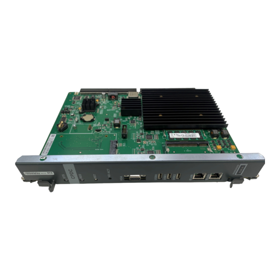
- Page 54 Page 54 of 436 Preparing for installation Figure 10 CP PIV call processor card (side) 512 MBytes DDR memory Rear Fixed Media Drive (FMD) Front Removable Media Drive (RMD) NN43021-310 Standard 06.01 March 2013...
- Page 55 Preparing for installation Page 55 of 436 Figure 11 CP PIV call processor card (front) Removable Media Drive (RMD) Lan 2 Lan 1 USB Port COM 2 COM 1 INIT RESET Large System Installation and Commissioning...
-
Page 56: Signaling Server
Page 56 of 436 Preparing for installation Signaling Server CS 1000M systems use a Signaling Server. The Signaling Server provides a central processor to drive the signaling for IP Phones and IP Peer Networking. The Signaling Server is a Common Processor Pentium Mobile... - Page 57 A system may be upgraded to the next larger system type as defined in Communication Server 1000M and Meridian 1 Large System Upgrade NTPs (NN43021-458 to 474). When expanding to the next system type, the changes to the physical configuration should be kept as simple as possible to reduce downtime and installation costs.
-
Page 58: Cable Routing Guidelines
Page 58 of 436 Preparing for installation Sending and receiving cables must be of equal lengths and as short as possible. In order to optimize network FIJI cabling, mount the NTD35 network modules in pairs in the same column, one module on top of the other in the middle tiers. - Page 59 Preparing for installation Page 59 of 436 Figure 13 Cable routing troughs – front view of module Cabling troughs 553-3117 A typical routing scenario from the faceplate of a printed circuit pack (PCP) to one of the I/O panels is as follows: •...
- Page 60 Page 60 of 436 Preparing for installation Since all faceplate to I/O panel cables are the same length and card positions in the card cage vary, a cable can contain excess slack. It is therefore recommended that cables from cards in the left side of the card cage use the right I/O panel and cables from cards in the right side of the card cage use the left I/O panel whenever possible, as shown in Figure 14.
- Page 61 EMI shielding.) Avaya recommends that you use the 90° connector end of the cable to route the cable through a module or cabinet instead of the 180° end, since some openings are small (see Figures 15 and 16).
-
Page 62: Equipment Handling Precautions
Page 62 of 436 Preparing for installation Figure 16 180° cable connector 553-7498 Equipment handling precautions To avoid personal injury and equipment damage, review the following guidelines before handling the equipment. Unloading equipment Special ramps, packed inside the pallet holding Column 0, must be used to move the equipment off the pallet. -
Page 63: Handling Circuit Cards
Preparing for installation Page 63 of 436 Working with power supplies There are no user-repairable components in the power supply. If a power supply fails, the complete unit must be replaced. Do not disassemble a power supply under any circumstances. DANGER OF ELECTRIC SHOCK To avoid the danger of electric shock, be careful when working with power equipment and... - Page 64 Page 64 of 436 Preparing for installation Figure 17 Static discharge points Module rear Wrist strap connection point Bare metal strip Power supply slot Module Wrist strap Bare metal strip front connection point 553-5000 NN43021-310 Standard 06.01 March 2013...
- Page 65 Preparing for installation Page 65 of 436 DenAn regulatory notice for Japan Large System Installation and Commissioning...
-
Page 66: Preparing The Equipment For Installation
Preparing for installation Preparing the equipment for installation Use the equipment room floor plan to position equipment. See Communication Server 1000M and Meridian 1 Large System Planning and Engineering (NN43021-220) to prepare the equipment room and floor plan. WARNING A fully loaded column weighs 275 kg (606 lb). More than one person is required to remove equipment from shipping pallets. - Page 67 Preparing for installation Page 67 of 436 With a flat blade screwdriver, turn the lock clockwise on the two locking latches (see Figure 18 on page 67). Figure 18 Locking latches on the module cover Slide to unlatch cover Turn lock screw up to lock 553-A0132 Simultaneously push the latches toward the center of the cover and...
- Page 68 Page 68 of 436 Preparing for installation Figure 19 Removing the pedestal grill Captive screw Captive screw 553-3054 Make sure all of the items on the system order form are on the packing slip that comes with the equipment. Inspect all equipment for physical damage. Report any damage to your supplier.
-
Page 69: Placing The Fourth Module On A Column
Page 69 of 436 Placing the fourth module on a column Contents This chapter contains information about the following topics: Overview ..........Placing the fourth module on a column . - Page 70 Page 70 of 436 Placing the fourth module on a column WARNING A fully loaded module weighs approximately 60 kg (130 lb). More than one person is required to place a module on a column. Procedure 2 Placing the fourth module on a column Position and secure the fourth module.
- Page 71 Placing the fourth module on a column Page 71 of 436 Figure 20 Module positioning guides Positioning guides Front Rear Opening for cables 553-3056 Large System Installation and Commissioning...
- Page 72 Page 72 of 436 Placing the fourth module on a column Figure 21 Module mounting bolts Mounting bolts 553-3057 Connect the module-to-module power and system monitor cables. Connect the power connectors between the modules (see Figure 22 page 73). Connect the system monitor cable from connector J2 on the third module to J1 on the fourth module.
- Page 73 Placing the fourth module on a column Page 73 of 436 Figure 22 Power and system monitor connections Top cap I/O safety panel Module 3 Power connectors between modules System monitor connector — J2 in Module 2 to J1 in Module 3 I/O safety panel Module 2...
- Page 74 Page 74 of 436 Placing the fourth module on a column NN43021-310 Standard 06.01 March 2013...
-
Page 75: Positioning And Leveling Equipment
Page 75 of 436 Positioning and leveling equipment Contents This chapter contains information about the following topic: Positioning and leveling the equipment ......Positioning and leveling the equipment Columns normally stand on adjustable feet that provide leveling capability and ground isolation. - Page 76 Page 76 of 436 Positioning and leveling equipment Position a level across the top module cover on the front of the column. Loosen the locking nuts on the feet. Adjust the feet on each pedestal up or down to level the column. Perform step a to step e for leveling the rear of the system.
- Page 77 Positioning and leveling equipment Page 77 of 436 Figure 23 Positioning spacer gaskets Gasket placement Rear Front 553-5641 Attach a spacer to one side of each module, except the end column (see Figures 24 and 25). — Position a spacer against the module. —...
- Page 78 Page 78 of 436 Positioning and leveling equipment Figure 24 Spacer positioning Rear Spacer Screw Stand-off Spacer 553-A0130 NN43021-310 Standard 06.01 March 2013...
- Page 79 Positioning and leveling equipment Page 79 of 436 Figure 25 Column positioning with spacers Step 1 Attach spacers to one side of each column (except the end column) (end column) Spacers Spacers Step 2 One at a time, push columns together, level, align, and attach the other side of the spacer Step 3 Positioning completed...
- Page 80 Page 80 of 436 Positioning and leveling equipment NN43021-310 Standard 06.01 March 2013...
-
Page 81: Installing Overhead Cable Tray Kits
Avaya offers an NT8D63 Overhead Cable Tray Kit, which provides equipment for mounting cable trays on four-tier columns. The kit includes two support brackets, and front and rear exhaust grills with cutouts for cable routing. - Page 82 Page 82 of 436 Installing overhead cable tray kits CAUTION — Service Interruption System Failure Column frames must be insulated from contact with building structures such as concrete walls, floors, and ceilings. Whether the cable racks are column-mounted or ceiling-hung, the installation must maintain the integrity of the grounding architecture.
- Page 83 Installing overhead cable tray kits Page 83 of 436 Figure 27 Overhead cable tray kit Bolt for bracket Customer-provided ladder rack J-bolt Bracket 553-3074 Install the front and rear air exhaust grills that come with the kit. Place the cable rack on top of the support brackets and fasten it to the supports with the J-bolts as shown in Figure 27.
- Page 84 Page 84 of 436 Installing overhead cable tray kits NN43021-310 Standard 06.01 March 2013...
-
Page 85: Installing Ac Power
Page 85 of 436 Installing AC power Contents This chapter contains information about the following topics: AC-powered systems........Safety ground/protective earth and logic return wiring . -
Page 86: Safety Ground/Protective Earth And Logic Return Wiring
#6 AWG or larger. It must connect the pedestal to the single-point ground (SPG). Using an isolated ground (IG) bus as the single-point ground is recommended. To fulfill this function, Avaya offers the NT6D5304 Logic Return Equalizer (LRE), equipped with nine terminations. - Page 87 Installing AC power Page 87 of 436 Multiple-column systems use an insulated ground bus as the point where the logic return wires from different columns are consolidated before connecting to the single-point ground. Figure 28 Single column – ground and logic return distribution AC input Large System Service...
- Page 88 Page 88 of 436 Installing AC power Figure 29 Multiple column – ground and logic return distribution AC input Large System Service panel 120 V receptacle IG or ACEG Safety ground (#6 AWG, min) Cord or conduit Logic return reference (#6 AWG) 208/240 V AC conduit...
- Page 89 Installing AC power Page 89 of 436 Figure 30 Multiple column, multiple row – ground and logic return distribution AC input Large System Common equipment columns Service panel 120 V receptacle IG or ACEG Safety ground (#6 AWG, min) Logic return reference (#6 AWG) AC conduit...
-
Page 90: Installing Safety Ground/Protective Earth And Logic Return Wiring
CAUTION — Service Interruption System Failure Failure to follow grounding procedures can result in unsafe or faulty equipment. See Communication Server 1000M and Meridian 1 Large System Planning and Engineering (NN43021-220) for a complete description of approved ground sources and methods. - Page 91 Installing AC power Page 91 of 436 Figure 31 PDU ground lug locations MAIN CIRCUIT BREAKER 8D53CB 553-8993 Ground lugs Connect the safety ground/protective earth wire (insulated ground wire must be used for system grounding). For a single-column system, connect a #6 AWG wire from the ground source in the service panel to a ground lug on the pedestal.
- Page 92 Page 92 of 436 Installing AC power Place a warning tag on the connection at the ground source. The warning tag should read WARNING—TELEPHONE SYSTEM GROUND CONNECTION—DO NOT DISCONNECT. Using a volt/ohm meter, measure the resistance between the ground pin on the power plug and the ground terminal on the power outlet.
-
Page 93: Installing Ups Ground Cabling
Figure 34 is a block diagram of a UPS installation and associated wiring. Follow Procedure 6 to install UPS ground cabling. Note: Because UPS installation can be complex, Avaya recommends that installers attend vendor training programs. Figure 34 AC reserve power configuration... - Page 94 Page 94 of 436 Installing AC power Procedure 6 Installing the UPS ground cabling CAUTION — Service Interruption Damage to Equipment Take care when connecting battery leads to the UPS. A battery reversal can result in severe damage to the UPS.
- Page 95 Installing AC power Page 95 of 436 Figure 35 UPS grounding diagram Column frame grounds Column 0 Column 1 Column n UPS frame grounds UPS 0 UPS 1 UPS n Bypass switch frame grounds Isolated ground bus Service panel 553-3089 Large System Installation and Commissioning...
- Page 96 Page 96 of 436 Installing AC power NN43021-310 Standard 06.01 March 2013...
-
Page 97: Installing Dc Power
Page 97 of 436 Installing DC power Contents This chapter contains information about the following topics: DC-powered systems........Candeo DC power systems . -
Page 98: Candeo Dc Power Systems
Page 98 of 436 Installing DC power Note: The procedures in this chapter apply to the global power distribution unit (PDU). Throughout this document, the global PDU is referred to as the NT4N49AA PDU. To install reserve power equipment (batteries), follow the instructions provided with the equipment. - Page 99 Installing DC power Page 99 of 436 Both Large and Small Candeo systems provide “plug and walk-away” installation and setup. The platform can be reconfigured or expanded while it remains online. Installation and maintenance benefits include: • fully front accessible •...
- Page 100 Candeo SP 48300 Power System User Manual (P7000154) • Candeo SP 48300 Power System Installation Manual (P7000289) • Candeo SP 48300 Power System Quick Installation Guide for Meridian 1 and Avaya Communication Server 1000 Systems (N0029343) NN43021-310 Standard 06.01 March 2013...
-
Page 101: Large Candeo Modules
Installing DC power Page 101 of 436 Large Candeo modules The Candeo platform uses a combination of modules or building blocks to deliver custom configurations. The modules include: Rectifier 50/48 Module System Manager Module Distribution 500 Module Rectifier 50/48 Module The shelfless Rectifier 50/48 provides up to 50 A (2 750 W) of –48 V DC power. - Page 102 Page 102 of 436 Installing DC power System Manager Module The System Manager is the main control element of the Large Candeo system. The System Manager’s local and remote system management capabilities provide total control over the power system. System Manager Module features include: •...
- Page 103 Installing DC power Page 103 of 436 Distribution Module features include: • Wide selection of distribution elements: — up to twenty, 1 to 100 A single pole circuit breakers — or up to ten, 100 to 150 A double pole circuit breakers —...
- Page 104 Page 104 of 436 Installing DC power Large Candeo sample configurations Example configuration #1 • 1.05 m (42 in.) Frame with battery kit, LVD and distribution 500 (with 20 breaker positions). • 17 mid trip breakers (30 A), one GMTX fuse block (takes up 3 breaker positions).
-
Page 105: Small Candeo Modules
Installing DC power Page 105 of 436 Small Candeo modules The Candeo platform uses a combination of modules or building blocks to deliver custom configurations. The modules include: • Rectifier 30/48 • Power shelves • System Manager SP • Distribution 300 panel Rectifier 30/48 The Rectifier –48 V DC, 1500 W is a switch-mode rectifier that converts the single-phase AC source at the input into an isolated, filtered, and regulated... - Page 106 Page 106 of 436 Installing DC power capacity of the supplementary shelf is 180 A (six rectifiers delivering 30 A each), but the sixth rectifier is for N+1 redundancy and kicks in only if one of the other rectifiers fails. System Manager SP The System Manager SP is the advanced controller available with the Candeo SP power systems.
- Page 107 Installing DC power Page 107 of 436 • remote or local access (PSTN, GSM, EEM, TCP/IP, SNMP) • local and remote Graphical User Interface (GUI) with multi-language compatibility Distribution 300 panel The Candeo SP48300 can have either one or two distribution panels. Each distribution panel can support 300 A.
- Page 108 Page 108 of 436 Installing DC power Enclosure, an enclosed shelf for use in Candeo racks. Each battery shelf can accommodate two modules, for a total of eight batteries. Small Candeo sample configurations Example configuration #1 A basic 120 A system (see Figure 36 on page 108): •...
- Page 109 Installing DC power Page 109 of 436 Example configuration #2 A 300 A system: • initial power shelf equipped with a System Manager SP and five 1500 W rectifiers • supplementary power shelf equipped with six rectifiers • initial distribution and battery connection panel with 18 plug-in positions for load protection devices and eight positions for battery protection devices Example configuration #3...
-
Page 110: Installation Reference Guide
Page 110 of 436 Installing DC power Figure 37 Small Candeo 300 A system with supplementary distribution panel Installation reference guide The Candeo system is easy to install. For more information about the Candeo SP 48300 Power System AP6C55AA, see Candeo Power Systems Installation Manual AP6C75 (P0914426) for the Large Candeo system, or Installation NN43021-310 Standard 06.01... - Page 111 Installing DC power Page 111 of 436 Manual (P7000289) for the Small Candeo system. The installation manuals cover the following topics. Large Candeo Site Preparation — Overview, tools and test equipment, precautions, and receiving materials. Locating and Erecting Frames — Locating and installing the frame on various floor types and consideration for earthquake anchoring.
-
Page 112: Configuration Reference Guide
Page 112 of 436 Installing DC power Cabling and connecting — Basic rules, specifications for connecting lugs, torque values for bolted lug to bus bar connections, cabling layouts, and procedures for cabling and connecting the ground leads, AC supplies for the rectifiers, DC load cables, miscellaneous cables, and final connections at the batteries. -
Page 113: Safety Ground/Protective Earth And Logic Return Wiring
Safety ground/protective earth and logic return wiring To ensure electrical system grounding integrity, follow the isolated ground topology for all Meridian 1 / Succession 1000M Large System equipment implementations. Isolated ground provides the best method for avoiding the introduction of ground noise to the system from other external equipment. -
Page 114: Cabling And Connecting The Grounding Leads
Note: For a more information about approved ground sources and methods, see Communication Server 1000M and Meridian 1 Large System Planning and Engineering (NN43021-220). You must use Insulated ground wire for system grounding. -
Page 115: Connecting The Power Plant Frame Ground (Or Safety Ground) Leads
Installing DC power Page 115 of 436 Note 1: In some equipment sites, depending on the grounding topology and the size of the building, the floor ground bar (FGB) and the building principal ground (BPG) may be the same busbar. Note 2: In some equipment sites, depending on the grounding topology, the power plant BRR ground bar may be determined as being the SPG. - Page 116 Page 116 of 436 Installing DC power Note 1: The frame ground collector cable is normally sized according to its length (distance between the main DC distribution cabinet and the FGB or BPG) as well as the maximum fuse or circuit breaker size that can be provided in the power plant.
- Page 117 Installing DC power Page 117 of 436 Table 4 Torque values for bolted connections (Part 2 of 2) Bolt size Threads/inch Torque (in.-lb) Tension (lb) 11 mm (7/ 5110 16 in.) 5120 13 mm (1/2 in.) 6110 6140 16 mm (5/8 in.) 7350 (see note) 19 mm (3/4 in.)
- Page 118 Page 118 of 436 Installing DC power Connect the other end of the cable to the FG collector with a parallel tap connector, as shown in the left side illustration of Figure 38 on page 118. Continue with step 4. Connect the other end of the cable to the nearest floor ground bar (FGB), which in some sites may be the building principal ground (BPG), as shown in the right side illustration of Figure 38 on...
- Page 119 Installing DC power Page 119 of 436 Figure 39 Connection of the frame ground lead inside the frame 553-AAA0759 Large System Installation and Commissioning...
- Page 120 Page 120 of 436 Installing DC power Figure 40 Ground and logic return distribution – Large and Small Candeo power systems AC input Large System Service panel 120 V receptacle IG or ACEG Safety ground (#6 AWG, min) BRE/LRE Note 1 Battery / logic return reference Optional...
-
Page 121: Four-Feed Pdu
Installing DC power Page 121 of 436 Four-Feed PDU The Four-Feed PDU (NT4N49AA) supports independent power feeds to each of four modules in a stack if required. However, in a typical installation where independent power feeds are not required, two jumper wires are provided to jumper adjacent battery leads. - Page 122 Page 122 of 436 Installing DC power The four breakers (one for each module) in the existing DC PDU (NT4N50AA) are rated at 18 A each. The same breakers in the four-feed PDU are rated at 28 A. Figure 42 Optional four-feed wiring Cable-tie saddle Cable restraint bar...
- Page 123 Installing DC power Page 123 of 436 Figure 43 PDU circuit protection - 48 V source NT4N49AA PDU Terminal block Circuit protection Max 30 A - BAT 0 - BAT 1 - 48 V Max 30 A - BAT 2 - BAT 3 + RTN 0 + RTN 1...
- Page 124 A maximum loop drop of 2 V is allowed between the pedestal, or junction box, and the external power equipment. See Table 5 for allowable wire sizes. For more information about calculating wire size, see Communication Server 1000M and Meridian 1 Large System Planning and Engineering (NN43021-220). Table 5...
- Page 125 Installing DC power Page 125 of 436 The following equipment is located in the rear of each pedestal (see Figure 44) in Large System columns. • The PDU distributes power to the entire column. • The field wiring terminal provides the connection point for wiring brought into the pedestal.
- Page 126 Page 126 of 436 Installing DC power With the NT4N49AA PDU, the safety ground/protective earth wires and all wiring to the terminal block in the PDU must be neatly routed within the cable-tie saddles and under the cable restraint bar at the base of the pedestal (see Figure 45 on page 126).
-
Page 127: Installing The Four-Feed Pdu
System Failure Failure to follow grounding procedures can result in unsafe or faulty equipment. For more information about approved grounding sources and methods, see Communication Server 1000M and Meridian 1 Large System Planning and Engineering (NN43021-220). Procedure 8 Installing safety ground/protective earth wiring... - Page 128 Page 128 of 436 Installing DC power next as illustrated in Figure 46, connecting all of the columns together (or run a #6 AWG wire from the ground source to each column individually). Note 1: Use only insulated ground wire for system grounding. Note 2: The safety ground/protective earth wire must be routed within the cable-tie saddles and under the cable restraint bar at the base of the pedestal.
-
Page 129: Connecting Power From The Power Plant To The Pdu
Installing DC power Page 129 of 436 Connecting power from the power plant to the PDU Note 1: It is good installation practice to fully wire out a pedestal, even if only one or two columns are being installed at first. This facilitates future expansion to a four-module column. - Page 130 Page 130 of 436 Installing DC power Connect the wires to the matching connections on the terminal block on the junction box. Connect the red wires to – BAT 0, – BAT 1, – BAT 2, and – BAT 3. Connect the black wires to + BATRTN 0, + BATRTN 1, + BATRTN 2, and + BATRTN 3.
- Page 131 Installing DC power Page 131 of 436 10 Replace the metal safety cover over the terminal block on the PDU. Lower the front panel over the mounting screws on the PDU. Tighten the screws holding the cover. 11 Replace the power plant cover. 12 Replace the junction box cover.
- Page 132 Page 132 of 436 Installing DC power Figure 47 PDU to Large Candeo connections 553-AAA0760 End of Procedure NN43021-310 Standard 06.01 March 2013...
-
Page 133: Connecting Uk Power To The Four-Feed Pdu
Installing DC power Page 133 of 436 Connecting UK power to the Four-Feed PDU To connect the external power system to the pedestal, use the following procedure for each column (this procedure gives the connections for a four-module column). Note: All wiring to the PDU must be routed within the cable-tie saddles and under the cable restraint bar at the base of the pedestal. -
Page 134: System Monitor Connections
Page 134 of 436 Installing DC power Connect the black BATRTN (+48 V) wires. At the 8B/2R or 8B/4R master power cabinet, connect wires to the +ve bus. At the PDU, connect the wires to the terminal block: Connect modules 0 to + BATRTN 0. Connect modules 1 to + BATRTN 1. - Page 135 Installing DC power Page 135 of 436 Figure 48 UEM to 8B/2R or 8B/4R master power cabinet connections To Test Jack Frame (TJF) Master Power Cabinet(s) 16 sq mm green/yellow Positive Bus Black wires Factory installed (16 sq mm Orange wire green/yellow) (10 sq mm) Logic Return Equalizer,...
- Page 136 Page 136 of 436 Installing DC power NN43021-310 Standard 06.01 March 2013...
-
Page 137: Planning And Designating A Main Distribution Frame
Page 137 of 436 Planning and designating a Main Distribution Frame Contents This chapter contains information about the following topics: About terminations ........Installation and designation. -
Page 138: Terminal Block Requirements
Planning and designating a Main Distribution Frame This chapter describes how to install and connect an Avaya Communication Server 1000M system using the BIX or Krone Test Jack Frame (UK) cross-connect terminals. Note: The examples shown here are BIX and Krone cross-connect systems. -
Page 139: Miscellaneous Equipment
Planning and designating a Main Distribution Frame Page 139 of 436 Procedure 11 Installing the BIX cross-connect terminal Refer to the equipment layout plan to determine where to place the cross-connect terminal. Lay out the terminal blocks as shown in Figure 51 on page 141. - Page 140 Page 140 of 436 Planning and designating a Main Distribution Frame Figure 50 BIX module Connector Designation strip 553-3097 NN43021-310 Standard 06.01 March 2013...
- Page 141 Planning and designating a Main Distribution Frame Page 141 of 436 Figure 51 Recommended layout for NT8D37 IPE Modules Cable terminations for one NT8D37 IPE Module From Cable A panel Cable B Cable C Cable D (Note) Cable E Cable F Cable G Cable H (Note) Cable K...
-
Page 142: Installing The Krone Cross-Connect System (Uk)
Page 142 of 436 Planning and designating a Main Distribution Frame Installing the Krone cross-connect system (UK) In the Krone cross-connect system, one terminating strip holds ten pairs of cable. When cross-connecting a 25-pair cable on this system, eight of the ten terminating points are used on each strip. - Page 143 Planning and designating a Main Distribution Frame Page 143 of 436 Figure 52 IPE module card allocation – Krone cross-connect system Pair Pair Card 15 Cable T Card 14 Cable S Card 13 Cable R Card 12 Card 11 Cable M Card 10 Cable L Card 9...
- Page 144 Page 144 of 436 Planning and designating a Main Distribution Frame Figure 53 CE/PE module card allocation – Krone cross-connect system Pair Pair Card 9 Cable K Card 8 Cable G Card 7 Card 6 Cable F Card 5 Cable E Card 4 Card 3 Cable C...
- Page 145 Planning and designating a Main Distribution Frame Page 145 of 436 There are two types of mandatory labels: those with safety warnings and those without. Mandatory labels with safety warnings are required for the following cards: • NT5K02 analog line card •...
- Page 146 Page 146 of 436 Planning and designating a Main Distribution Frame Figure 55 Label for Analog Tie Trunk Card Figure 56 Label for Data Access Line Card (NT7D16) SAFETY WARNING LOOP..SHELF..CARD..DATA EQUIPMENT SEE INSTRUCTIONS FOR USE : Unit: Dir.
- Page 147 Planning and designating a Main Distribution Frame Page 147 of 436 Figure 57 Label for Power Failure Transfer Unit SAFETY WARNING POWER FAIL TRANSFER UNIT CABLE SEE INSTRUCTIONS FOR USE PFT 1 LINE CO TRK. CARD CARD SAFETY WARNING POWER FAIL TRANSFER UNIT CABLE SEE INSTRUCTIONS FOR USE PFT 2...
- Page 148 Page 148 of 436 Planning and designating a Main Distribution Frame Figure 59 Label for Exchange Line Trunk Card (NT5K18) LOOP..EXCHANGE LINES SHELF..CARD..EXCHANGE NO.'S LOOP..EXCHANGE LINES SHELF..CARD..EXCHANGE NO.'S LOOP..EXCHANGE LINES SHELF..CARD..EXCHANGE NO.'S 553-6466 Figure 60 Label for Direct Dial Inward Trunk Card (NT5K17)
-
Page 149: Installing Power Failure Transfer Units
Page 149 of 436 Installing Power Failure Transfer Units Contents This chapter contains information about the following topics: PFTU configurations ........Installing a PFTU . - Page 150 Page 150 of 436 Installing Power Failure Transfer Units Designated telephones (DTMF or rotary dial types) Central office trunks Figure 61 MDF terminations for typical PFTU operation PFTU PFTU Telephone/CO trunk terminations terminations terminations System alarm (J3) Auxiliary terminations System monitor power supply normally -48V...
- Page 151 Installing Power Failure Transfer Units Page 151 of 436 Figure 62 Typical PFTU connection to the MDF and the Master System Monitor 50220-07 DEES 154 – 48 V Power Supply PFTU Meridian 1 – 48V master system P1–49 BATT monitor (SM) P1–24 P2–25 Open...
-
Page 152: Installing A Pftu
Page 152 of 436 Installing Power Failure Transfer Units Installing a PFTU Use the following procedure and any instructions provided with the Power Failure Transfer Unit (PFTU) to install and connect PFTUs. Procedure 13 Installing a PFTU Install a PFTU according to the manufacturer’s instructions. Attach the yellow PFTU label to the designation strip, indicating the top connector as P1 and the bottom connector as P2. -
Page 153: Connecting Trunks And Telephones
Installing Power Failure Transfer Units Page 153 of 436 Connect a #24 (or larger) AWG wire from the ground (GND) connection on the auxiliary power supply to the PFTU termination area on the MDF. Connect a second #24 (or larger) AWG wire from the GND connection on the auxiliary power supply to the Large System alarm termination area on the MDF. -
Page 154: Installing Qua6 Pftus
Page 154 of 436 Installing Power Failure Transfer Units For each trunk assigned to the PFTU. • Connect the tip and ring of the CO card to the third pair of the assigned PFTU. • Connect the tip and ring of the trunk to the fourth pair of the assigned PFTU. -
Page 155: Configuring The System Monitor
Page 155 of 436 Configuring the system monitor Contents This chapter contains information about the following topics: System monitor cabling........Configuring the System Monitor. - Page 156 Page 156 of 436 Configuring the system monitor Figure 63 System monitor to system monitor serial link cabling Column 0 Column 1 Column n Master XSM Slave XSM Slave XSM Pedestal Pedestal Pedestal n=63 maximum NT8D46AL NT8D46AP 553-7551 Power failure transfer control The system monitor can be cabled to the MDF to provide power failure transfer control or additional alarms.
-
Page 157: Configuring The System Monitor
Configuring the system monitor Page 157 of 436 Configuring the System Monitor The master System Monitor (NT8D22) interfaces with a Serial Data Interface (SDI) port in the column with CPU 0. Procedure 15 Configuring the System Monitor (NT8D22) Set the baud rate for the SDI port associated with the system monitor to 1200 baud in DTE mode. - Page 158 Page 158 of 436 Configuring the system monitor with CPU 1 as slave unit 1. Number the slaves sequentially wherever possible. Table 8 Switch settings for master in multiple-column system Switch on** To configure positions 3–8, see Table 10 Set to on for a DC-powered system; set to off for an AC-powered system. Set to off if the system is not equipped with a PFTU.
- Page 159 Configuring the system monitor Page 159 of 436 Table 10 SW2 on master—total number of slaves in the system (Part 2 of 2) Switch position Switch position How many How many slave units slave units Large System Installation and Commissioning...
- Page 160 Page 160 of 436 Configuring the system monitor Table 11 SW2 on slaves—total unit number for the slaves (Part 1 of 2) Switch position Switch position Slave unit Slave unit address address NN43021-310 Standard 06.01 March 2013...
-
Page 161: Cabling The System Monitor
Configuring the system monitor Page 161 of 436 Table 11 SW2 on slaves—total unit number for the slaves (Part 2 of 2) Switch position Switch position Slave unit Slave unit address address Note: **Slave addresses are 1-63. End of Procedure Cabling the System Monitor The System Monitor (NT8D22) is used to monitor the temperature, power supplies, and blower unit in a column. - Page 162 Page 162 of 436 Configuring the system monitor Figure 64 System monitor module-to-module cabling Top Cap NT8D46AC Backplane Backplane Module NT8D46AA Backplane Backplane NT8D46AB Pedestal 553-7544 Follow the steps in Procedure 16 to cable the NT8D22 System Monitor. Procedure 16 Cabling the System Monitor (NT8D22) Remove the I/O safety panel in the rear of the module with CPU 0.
- Page 163 Configuring the system monitor Page 163 of 436 Connect the master system monitor to slave unit 1 with an NT8D46AS cable. Connect the narrow ribbon on an NT8D46AG cable from connector J2 in the module with CPU 0 to the assigned port on the SDI card (see Figure 65).
- Page 164 Page 164 of 436 Configuring the system monitor Figure 66 Cabling CS 1000M SG or Meridian 1 Option 61C, single column with stacked Core/Net modules – cable master system monitor to SDI port To SDI port To next module NT8D46AG...
- Page 165 Configuring the system monitor Page 165 of 436 Figure 67 Multiple-column system monitor connections Column 0 Slave unit 1 Master system monitor Slave unit n From J6 To J5 From J6 to Terminate on J5 on master on slave 1 J5 on slave 2 of last column in series To J5 of next...
- Page 166 Page 166 of 436 Configuring the system monitor Note 1: The system monitor to MDF cable is available in three lengths: NT8D46BH (9.75 m/32 ft), NT8D46EH (30 m/100 ft), and NT8D46DH (45 m/150 ft). Note 2: If additional contact closures are required through the J3 REMALMA or REMALMB leads (for a hard alarm in case a column loses power, for example), additional system monitor to MDF cables can be ordered.
- Page 167 Configuring the system monitor Page 167 of 436 For AC-powered systems with a UPS: Connect the appropriate cable (see the following list) from connector J4 on the system monitor in the column with CPU 0 (the master system monitor) to the associated UPS. Table 13 gives the pin assignments and signal descriptions for the alarm cables.
- Page 168 Page 168 of 436 Configuring the system monitor Figure 68 UPS alarm cabling Large System columns J4 on system monitor J4 on system monitor UPS alarm cable UPS for each column 553-3088 For DC-powered systems, extend the alarm and trip leads from connector J4 on the system monitor in the column with CPU 0 (the master system monitor) to the external power equipment using an NT8D46AV cable (see Table 14 on...
-
Page 169: Alarm Interfacing To Candeo
Configuring the system monitor Page 169 of 436 Table 14 Alarm and trip lead connections—NT8D46AV Cable Connection at control and distribution panel Color Description Terminal block No Pwr Sys Alarm Name Alarm TB2 Position 6 Low Float DCON 0 TB4 Position 8 Rectifier Fail Alarm DCON 1* TB5 Position 2... - Page 170 Page 170 of 436 Configuring the system monitor • remote access — by means of the web browser on a computer connected through a dial-up network connection into the RS-232 port, using an external modem — by means of the web browser on a computer connected remotely through a LAN or WAN network connection into the RJ-45 network interface Monitoring alarms allows the Large System to report conditions such as low...
- Page 171 Configuring the system monitor Page 171 of 436 • Main AC fail • Rectifier fail major (RFA major) • Low voltage disconnect (LVD) • High voltage (HV) • Fuse alarm (FA) • Priority low voltage disconnect • AC input over-voltage •...
-
Page 172: Configuring The Alarm Ports
Page 172 of 436 Configuring the system monitor Table 16 Cable lengths Cable Length NT8D46AV 9.75 m (32 ft) NT8D46BV 19.5 m (64 ft) NT8D46CV 30 m (100 ft) Cabling the Candeo There are eight configurable Candeo output ports for output alarms. Each output port can use one of the following three contact types: normally open, normally closed, and common. -
Page 173: Customizing Alarms
Configuring the system monitor Page 173 of 436 Procedure 17 Configuring the alarm ports Select “Alarm Severity and Output” from the System Manager display screen. Under “Alarm Name”, select the line with “AC Fail”, and change “Output Port” to 1. Under “Alarm Name”, select the line with “Major”, and change “Output Port”... - Page 174 Page 174 of 436 Configuring the system monitor NN43021-310 Standard 06.01 March 2013...
-
Page 175: Connecting A System Terminal Or Modem
Page 175 of 436 Connecting a system terminal or modem Contents This chapter contains information about the following topics: About the system terminal........Connecting a terminal . - Page 176 Page 176 of 436 Connecting a system terminal or modem Figure 69 Terminal connection diagram During the initial installation of a dual CPU system, you may want to temporarily install additional terminals for split mode monitoring, or programming, or both. Note: In a Large System, I/O ports on the Call Processing (CP) cards can be used to monitor CPU operations.
-
Page 177: Connecting A Terminal
The ABCDE-Switch, which provides up to four-to-one switching, is available from Avaya as part number A0377992. The switch box can be used to connect the SDI and COM1 and COM2 ports to a terminal or a modem. If used, one switch box must be used for terminals and one for modems. -
Page 178: Connecting A Terminal To A Com Port
Page 178 of 436 Connecting a system terminal or modem Terminals connected to the COM1 ports can be installed as follows. One terminal connects to a COM1 port in one CPU (the cable is switched from module to module as needed); one terminal is required in addition to the terminal for the SDI port connection (see Figure 70 on page 179). -
Page 179: Connecting A Switch Box And Terminal To Com1 And Com2 Ports
Connecting a system terminal or modem Page 179 of 436 Figure 70 One terminal for the COM1 ports Terminal NT8D95 cable J25 on I/O panel Terminal Network Module SDI port on Core/Net 1 I/O panel Core/Net 0 NT8D95 cable Rear View 553-A0133 Connecting a switch box and terminal to COM1 and COM2 ports... - Page 180 Page 180 of 436 Connecting a system terminal or modem To communicate directly with a COM1 port, switch the cable as needed. The terminal connected to the SDI port will always communicate with whichever CPU is active. End of Procedure Figure 71 One terminal and a switch box to two COM1 ports Terminal...
-
Page 181: Sdi And Com1 Ports
Connecting a system terminal or modem Page 181 of 436 Connecting a switch box and terminal to SDI and COM1 ports Use Procedure 20 to connect COM1 ports to a switch box and a terminal (see Figure 71 on page 180 and Figure 72 on page 182). -
Page 182: Connecting A Modem
Page 182 of 436 Connecting a system terminal or modem Figure 72 One terminal and a switch box to the SDI and COM1 ports Network Module SDI port on I/O panel J25 on J25 on I/O panel I/O panel Core/Net 1 Core/Net 0 NT8D95 NT8D95... - Page 183 RS-232 cable are required in all modem configurations. Required and recommended specifications for local end modems are: Required: true, not buffered, 9600 baud support (required for remote Avaya technical support) Required: CCITT V.32 or V.32bis compliance Recommended: the ability to adjust to lower and higher speeds, depending on line quality, while maintaining 9600 baud at local DTE Recommended: V.42 error correction...
-
Page 184: Configuring A Modem
Page 184 of 436 Connecting a system terminal or modem Configuring a modem Use Procedure 21 to configure the modem. You must configure the modem before you connect it to the Large System. A terminal, such as a PC computer, is required to configure the modem. -
Page 185: Connecting A Modem To An Sdi Port
Connecting a system terminal or modem Page 185 of 436 Table 18 Modem Commands Command Effect AT&F Load active profile. AT&H0 Flow control disabled. AT&D3 Resets on receipt of DTR. AT&S1 Modem controls DSR. ATS0=1 Answer after 1 ring. ATS2=128 Escape character = ASCII 128. - Page 186 Page 186 of 436 Connecting a system terminal or modem At the local end, configure the modem. Follow the manufacturer’s instructions to set the modem for 9600 baud, auto answer, dumb mode, command recognition OFF, command echo OFF. At the local end, connect an NT8D95 cable to the SDI port on the I/O panel in the rear of the module and to the modem.
-
Page 187: Connecting A Modem To Switch Box, Com2 Ports, Sdi Ports
Connecting a system terminal or modem Page 187 of 436 Figure 73 Modem to SDI port Smart mode RJ11 Terminal modem jack Modem cable RS-232 Remote end (or NT8D46) cable Public phone network RJ11 Dumb mode SDI port on jack modem I/O panel Network module... - Page 188 Page 188 of 436 Connecting a system terminal or modem At the local end, configure the modem. Follow the manufacturer’s instructions to set the modem for 9600 baud, autoanswer, dumb mode, command recognition OFF, and command echo OFF. At the local end, connect NT8D95 cables to: •...
- Page 189 Connecting a system terminal or modem Page 189 of 436 Figure 74 Modem to a switch box and SDI and COM2 ports (dual-column systems) Smart mode RJ11 modem Terminal jack Modem cable RS-232 Remote end (or NT8D46) cable SDI port on Public phone I/O panel network...
- Page 190 Page 190 of 436 Connecting a system terminal or modem Figure 75 Modem to a switch box and SDI and COM2 ports (single-column systems) Smart mode RJ11 modem jack Modem cable RS-232 Remote terminal (or NT8D46) cable SDI port Public phone I/O panel network Core/Net 1...
-
Page 191: Cabling Common Equipment In A Single Group System
Page 191 of 436 Cabling Common Equipment in a Single Group system Contents This chapter contains information about the following topics: Cabling guidelines......... Core/Net module . - Page 192 Page 192 of 436 Cabling Common Equipment in a Single Group system the secondary shrouds, which provide mechanical guidance for cable connectors. Because the cable troughs and spaces on the sides of a module are within the EMI shielding of the system, unshielded cables can be routed in those areas. As space permits, Common Equipment cables can be routed horizontally in the cable troughs at the front, rear, and sides of the module or vertically on the sides of the module.
-
Page 193: Core/Net Module
Cabling Common Equipment in a Single Group system Page 193 of 436 Figure 76 NT4N41 Core/Net shelf fanout panel (backplane) NT4N89 cable Network backplane Core backplane System Monitor (XSM) connections Group 2 Group 1 Group 6 Group 5 Group 4 Group 3 Group 7 slot 11... - Page 194 Page 194 of 436 Cabling Common Equipment in a Single Group system Reviewing Core/Net module placement Core/Net modules can be installed side-by-side on top of separate pedestals (see Figure 77) for power and cooling redundancy or in a stacked configuration (see Figure 78) in a single column. Core/Net 1 is always on the left.
- Page 195 Cabling Common Equipment in a Single Group system Page 195 of 436 Figure 78 Side-by-side configuration of Core/Net modules 553-AAA0756 Large System Installation and Commissioning...
- Page 196 Page 196 of 436 Cabling Common Equipment in a Single Group system Reviewing required Core cards All Core cards are installed in the factory. See Table 19 for the Core card requirements for each Core/Net module. For module and card descriptions, see “System equipment –...
-
Page 197: Cabling The Core Side
Cabling Common Equipment in a Single Group system Page 197 of 436 NT4N48 System Utility card. The System Utility card is located in slot c15. NT4N39AA Call Processor PIV (CP PIV). This card is located in the slot marked CP. Cabling the Core side This section describes installation of the Core cables. - Page 198 Page 198 of 436 Cabling Common Equipment in a Single Group system Figure 79 Core/Net cable connections (top view) NT4N4405 Shelf Power cable J31: Ethernet cable (factory installed) from LAN 1 NT4N90BA NT4N89AA System Monitor cable (factory installed) J25: DTE cable from COM 1 NT4N88AA (for terminal) J21: DCE cable...
-
Page 199: Cabling The I/O Panel
Cabling Common Equipment in a Single Group system Page 199 of 436 Figure 80 CP PIV Core and Network backplanes NT4N89 cable Network backplane Core backplane System Monitor (XSM) connections Group 6 Group 5 Group 4 Group 3 Group 2 Group 1 Group 7 slot 11... - Page 200 Page 200 of 436 Cabling Common Equipment in a Single Group system CAUTION — Service Interruption Loss of Data Label all cables on both ends before installation. Labels help ensure that the cables are properly routed and connected. Cable labels also help installers to troubleshoot problems and replace equipment.
-
Page 201: Cabling The Network Side
Cabling Common Equipment in a Single Group system Page 201 of 436 Cabling the Network side Table 22 lists the number of circuit cards required by each system. Table 23 lists the number of net cables required by each system. Table 22 Required Net side cards Quantity... -
Page 202: Configuring And Cabling The Clock Controllers
Page 202 of 436 Cabling Common Equipment in a Single Group system Figure 81 CP PIV Core/Net Module slot Core cCNI CPPIV UTIL LAN 1 LAN 2 COM 1 COM 2 INIT RESET PWR HDD PS 0 10 11 c9 c10 c11 c12 c13 c14 c15 CP Configuring and cabling the Clock Controllers Two Clock Controller cards (NTRB53) are required in each system to synchronize functions. -
Page 203: Network Group 0: Shelf 0 To Shelf 1
Cabling Common Equipment in a Single Group system Page 203 of 436 Procedure 25 Connecting the Clock Controller cables See Figure 85 on page 209. Connect P1 of the NT8D75 cable to port J3 of Clock Controller 0. Connect P2 of the NT8D75 cable to port J3 of Clock Controller 1. End of Procedure Network Group 0: Shelf 0 to Shelf 1 Each Single Group System contains one Network group, Group 0. -
Page 204: Inspecting Cni To 3Pe Factory Installed Cables
Page 204 of 436 Cabling Common Equipment in a Single Group system Procedure 26 Connecting the 3PE faceplates in the Core/Net modules Connect a NT8D80 cable from the J4 port in the Core/Net 0 3PE card to J4 port in the Core/Net 1 3PE card. Connect a second NT8D80 cable from the J3 port in Core/Net 0 to the J3 port in Core/Net 1. - Page 205 Cabling Common Equipment in a Single Group system Page 205 of 436 Use the extraction tool to disconnect the NT4N29 cables from the Core backplane. Connect the cables to the appropriate group (see Table 24). Table 24 Fanout panel to 3PE card connectors Group Fanout Panel Number...
-
Page 206: Connecting The Core/Net Backplanes
Page 206 of 436 Cabling Common Equipment in a Single Group system Connecting the Core/Net backplanes The Shelf 0 and Shelf 1 backplanes must be connected with two NT8D99AD cables (Core/Net modules only). Procedure 28 Connecting the Core/Net backplanes Connect one NT8D99AD cable from the “E” port in Core/Net 0 to the “E” port in Core/Net 1. -
Page 207: Optioning The System Utility Card
Cabling Common Equipment in a Single Group system Page 207 of 436 Optioning the System Utility Card To install the system utility card, first identify Core/Net 0 and Core/Net 1 shelves. Then adjust the DIP switches according to Table 25. Table 25 System Utility Card DIP switch settings Core/Net 0... -
Page 208: Connecting Core Modules To A Lan
Page 208 of 436 Cabling Common Equipment in a Single Group system Connecting Core modules to a LAN Connect each Core/Net module to a local area network (LAN). This connection provides a communication channel for LAN-based systems management tools such as Element Manager. This connection also supplies additional redundancy capabilities. - Page 209 Cabling Common Equipment in a Single Group system Page 209 of 436 Figure 85 CP PIV to I/O panel connections Core shelf (front of module) I/O Panel (rear of module) Core NTRE40AA Ethernet Adapter cCNI UTIL LAN 1 LAN 1 LAN 2 COM 1 COM 2...
-
Page 210: Cabling Common Equipment In A
Page 210 of 436 Cabling Common Equipment in a Single Group system Figure 86 Options for LAN 1 connections End of Procedure NN43021-310 Standard 06.01 March 2013... -
Page 211: Cabling Common Equipment In A Multi Group System
Page 211 of 436 Cabling Common Equipment in a Multi Group system Contents This chapter contains information about the following topics: Cabling guidelines......... Core/Net module . - Page 212 Page 212 of 436 Cabling Common Equipment in a Multi Group system which faces the front of the module, contains the primary shrouds, which provide mechanical guidance for the pins of the card edge connectors. The secondary side of the backplane, which faces the rear of the module, contains the secondary shrouds, which provide mechanical guidance for cable connectors.
-
Page 213: Core/Net Module
Cabling Common Equipment in a Multi Group system Page 213 of 436 Figure 87 NT4N41 Core/Net shelf fanout panel (backplane) NT4N89 cable Network backplane Core backplane System Monitor (XSM) connections Group 5 Group 4 Group 3 Group 2 Group 1 Group 7 Group 6 slot 12... - Page 214 Page 214 of 436 Cabling Common Equipment in a Multi Group system Reviewing Core/Net module placement Core/Net modules are installed side-by-side on top of separate pedestals, for power and cooling redundancy. Core/Net 1 is always on the left. Core/Net 0 is always on the right (see Figure 88 on page 215).
- Page 215 Cabling Common Equipment in a Multi Group system Page 215 of 436 Figure 88 Side-by-side placement of CP PIV Core/Net modules PE Module PE Module PE Module PE Module Module 3 Module 3 Module 3 Module 3 (IPE) (IPE) (IPE) (IPE) Module 2 Module 2...
-
Page 216: Cabling The Core/Net Module Backplane
Page 216 of 436 Cabling Common Equipment in a Multi Group system Checking Core card (front side) installation All Core cards are factory installed. The Core cards (front side) are: NT4N65 cPCI Core Network Interface (cCNI) cards. Each system contains between one and four NT4N65 cCNI cards per Core/Net Module. -
Page 217: Disconnecting Cables From The Core/Net Module Backplane
Cabling Common Equipment in a Multi Group system Page 217 of 436 Procedure 30 Cabling the Core/Net module backplane Orient the cable connector so the strain relief paddle is to the right. Partially insert the cable connector so its guides mate to the corresponding backplane connector. - Page 218 Page 218 of 436 Cabling Common Equipment in a Multi Group system Procedure 31 Disconnecting cable connectors from the backplane Use extreme caution to avoid bending or breaking backplane pins. Do not insert the extraction tool unless the cable connector is locked into the securing clip.
-
Page 219: Optioning The System Utility Card
Cabling Common Equipment in a Multi Group system Page 219 of 436 Optioning the System Utility Card To install the system utility card, first identify Core/Net 0 and Core/Net 1 shelves. Then adjust the DIP switches according to Table 27 below. Table 27 System Utility Card DIP switch settings Core/Net 0... -
Page 220: Core Shelf Cabling
Page 220 of 436 Cabling Common Equipment in a Multi Group system Figure 89 Core card placement in the NT4N41 Core/Net Module (front) Core Core MMDU cCNI Sys Util CPPIV cCNI Sys Util CP PIV Card status LEDs Card status LEDs (internal check) Compact Flash (RMD) (internal check) - Page 221 Cabling Common Equipment in a Multi Group system Page 221 of 436 Figure 90 Card placement in the NT4N41 Core/Net Module Core cCNI UTIL LAN 1 LAN 2 COM 1 COM 2 INIT RESET PS 0 10 11 c9 c10 c11 c12 c13 c14 c15 CP 553-9123r26revised Required Core cables Table 28 on...
- Page 222 Page 222 of 436 Cabling Common Equipment in a Multi Group system Table 28 Field installed Core cables (internal) (Part 2 of 2) Number required Order Code Description per system Customer supplied Standard CAT5 Ethernet cable (I/O Panel to LAN switch) Note: If there is no connection to a LAN, connect the two LAN 1 connectors using the NTRC17BA crossover cable.
- Page 223 Cabling Common Equipment in a Multi Group system Page 223 of 436 Figure 91 Core/Net cable connections (top view) NTND14 cables:cCNI to 3PE cables in Network Shelves ( Customer install Group 1 cable) NT4N4405 Shelf Power cable J31: Ethernet cable (factory installed) from LAN 1 NT4N90BA NT4N89AA System Monitor cable...
-
Page 224: Installing The Cp Piv To I/O Panel Cables
Page 224 of 436 Cabling Common Equipment in a Multi Group system Figure 92 CP PIV Core and Network backplanes NT4N89 cable Network backplane Core backplane System Monitor (XSM) connections Group 7 Group 6 Group 5 Group 4 Group 3 Group 2 Group 1 slot 12... - Page 225 Cabling Common Equipment in a Multi Group system Page 225 of 436 Figure 93 on page 226 displays the COM and LAN cable connections. CAUTION — Service Interruption Damage to Equipment Label all cables on both ends before installation. Labels help ensure that the cables are properly routed and connected.
- Page 226 Page 226 of 436 Cabling Common Equipment in a Multi Group system Figure 93 I/O panel connections Core shelf (front of module) I/O Panel (rear of module) Core NTRE40AA Ethernet Adapter cCNI UTIL LAN 1 LAN 1 LAN 2 COM 1 COM 2 INIT RESET...
-
Page 227: Connecting The Core Module To A Lan
Cabling Common Equipment in a Multi Group system Page 227 of 436 Connecting the Core module to a LAN Connect each Core/Net module to a local area network (LAN). This connection provides a communication channel for LAN based systems management tools such as Element Manager. This connection also supplies additional redundancy capabilities. -
Page 228: Cabling A Dual Ring Fiber Network
Page 228 of 436 Cabling Common Equipment in a Multi Group system Figure 94 Options for LAN 1 connections End of Procedure Cabling a Dual Ring Fiber Network The FIJI cards in the Network modules are connected to form a Dual Ring Fiber Network. - Page 229 Cabling Common Equipment in a Multi Group system Page 229 of 436 (Figure 95 on page 229). Four steps are required to configure the Fiber Network: • “Installing the Shelf 0 fiber optic ring (ascending)” on page 236. • “Installing the Shelf 1 fiber optic ring (descending)” on page 237.
- Page 230 NTRB53 Global Clock Controller cards The CS 1000M MG and Meridian 1 PBX 81C CP PIV support a Fiber Network Fabric network system with a Fiber Junctor Interface (FIJI) card. The double-slot FIJI (NTRB33AF) card resides in slots 8 and 9 on the Net side of the Core/Net module.
- Page 231 Cabling Common Equipment in a Multi Group system Page 231 of 436 Required cables Table 31 on page 231 outlines the required cables. Cable lengths will vary depending on system configuration. Table 31 Required cables Cable type Quantity Order Code Description Fiber Ring cable 1 per FIJI card...
-
Page 232: Fiji Card Cabling
Page 232 of 436 Cabling Common Equipment in a Multi Group system WARNING The shortest Fiber Cable must always be used. The cables from Group 0 to Group 1 must always be the same length as the cables from the last group back to Group 0 The delta between the lengths of each fiber ring from Group 0 to any other group must not exceed 15 m... - Page 233 Cabling Common Equipment in a Multi Group system Page 233 of 436 Figure 96 Double slot FIJI card faceplate LCD Display Latch ENB/DIS Switch FIJI ENBL/DIS LEDs TX Port (J1) RX Port (J2) CLK/FIJI 1 CLK/FIJI 2 MAINT Serial Port Latch 553-8649 Large System Installation and Commissioning...
- Page 234 Page 234 of 436 Cabling Common Equipment in a Multi Group system Figure 97 Single slot FIJI card faceplate NN43021-310 Standard 06.01 March 2013...
- Page 235 Cabling Common Equipment in a Multi Group system Page 235 of 436 Optical Cable Management Card (OCMC) Because fiber optic cables are easily damaged if bent, the NTRE39 Optical Cable Management Card (OCMC) is installed in Network modules to store and protect excess cable length.
-
Page 236: Installing The Shelf 0 Fiber Optic Ring (Ascending)
Page 236 of 436 Cabling Common Equipment in a Multi Group system Installing the Shelf 0 fiber optic ring (ascending) To create the Shelf 0 fiber optic loop, connect the FIJI cards in each Network Shelf 0 in ascending order (Figure 99 on page 237). -
Page 237: Installing The Shelf 1 Fiber Optic Ring (Descending)
Cabling Common Equipment in a Multi Group system Page 237 of 436 Figure 99 Shelf 0 fiber optic ring on a 4 group machine Shelf 0 fiber optic ring Group 1, shelf 1 Group 2, shelf 1 Group 3, shelf 1 Tx (J1) Tx (J1) Tx (J1) - Page 238 Page 238 of 436 Cabling Common Equipment in a Multi Group system Continue to connect NTRC48xx FIJI Fiber Ring Cables of the appropriate length from the Tx (J1) port to the Rx (J2) port in Shelf 1 of each Network group.
-
Page 239: Fiji To Fiji Cabling
Cabling Common Equipment in a Multi Group system Page 239 of 436 FIJI to FIJI cabling The FIJI cards in Shelf 0 and Shelf 1 of each Network group (except Group 0) must be directly connected with a NTRC47AA FIJI to FIJI Synch Cable cable. -
Page 240: Connecting The Clock Controller Cables
Page 240 of 436 Cabling Common Equipment in a Multi Group system Connecting the Clock Controller cables Two Clock Controller cards are required in each system. These cards synchronize Large System functions. Figure 102 on page 241 shows the two Clock Controllers installed in a two-column system. - Page 241 Cabling Common Equipment in a Multi Group system Page 241 of 436 Figure 102 Clock Controller placement CE Module CE Module Group 2, Group 1, shelf 1 shelf 1 CE Pwr Sup CE Pwr Sup IGS 1 IGS 0 IGS 1 IGS 0 Common Equipment Network Group...
- Page 242 Page 242 of 436 Cabling Common Equipment in a Multi Group system At Clock 0: Connect the “J1 Clock” end of a Clock to FIJI cable (NTRC46Ax) to the J1 end of the Clock to Clock cable. At Clock 1: Connect the “J1 Clock“ end of a second Clock to FIJI cable (NTRC46Ax) to the J2 end of the Clock to Clock cable.
- Page 243 Cabling Common Equipment in a Multi Group system Page 243 of 436 Figure 103 Clock Controller cable configuration NTRC49 cable J1 Clock J1 Clock FIJI card FIJI card Group 0, Group 0, shelf 1 shelf 0 FIJI FIJI ENBL/DIS ENBL/DIS CLK/FIJI 1 CLK/FIJI 1 CLK/FIJI 2...
- Page 244 Page 244 of 436 Cabling Common Equipment in a Multi Group system NN43021-310 Standard 06.01 March 2013...
-
Page 245: Cabling Lines And Trunks
Page 245 of 436 Cabling lines and trunks Contents This chapter contains information about the following topics: Overview ..........Cabling an IPE Module or Media Gateway . - Page 246 Page 246 of 436 Cabling lines and trunks Table 32 NT8D37 cable connections Backplane slots–shroud rows I/O panel/cable designation L0–1, 2, 3 L1–1, 2, 3 L2–1, 2, 3 L3–1, 2, 3 L4–1, 2, 3 L5–1, 2, 3 L6–1, 2, 3 L7–1, 2, 3 L8–1, 2, 3 L9–1, 2, 3...
-
Page 247: Cabling An Ipe Module Or Media Gateway
Cabling lines and trunks Page 247 of 436 Media Gateway cabling requirements Media Gateways require the following: • Each Media Gateway and Media Gateway Expander requires up to four 25-pair cables: — one 25-pair cable for each slot that is equipped with a trunk or line circuit card —... - Page 248 Page 248 of 436 Cabling lines and trunks Procedure 38 Cabling an IPE Module (NT8D37) or Media Gateway Select an appropriate number of NE-A25B (or equivalent) cables long enough to run from the I/O panels on the rear of the module or backplanes of the Media Gateway or Expander, to the MDF.
- Page 249 Cabling lines and trunks Page 249 of 436 Figure 105 NT8D37 IPE Module I/O panels Left Right 553-5928 End of Procedure Large System Installation and Commissioning...
-
Page 250: Connecting Lines And Trunks
Page 250 of 436 Cabling lines and trunks Connecting lines and trunks Follow Procedure 39 to connect lines and trunks. Ensure that wiring is not reversed and is on the proper terminals. Allow enough slack in the wiring to allow tracing and to reconnect wires if they break at the terminal. Procedure 39 Connecting lines and trunks Extend incoming wiring (such as cables from the central office or wiring... - Page 251 Cabling lines and trunks Page 251 of 436 Table 33 Line and trunk pair-termination tables NT8D37 IPE Module Table 34 on page 251 Line cards NT8D14 Universal Trunk Card: Trunk cards Table 35 on page 253 NT8D15 E&M Trunk Card: Table 36 on page 254 through to Table 38 on...
- Page 252 Page 252 of 436 Cabling lines and trunks Table 34 NT8D37 IPE Module: line card pair-terminations (Part 2 of 2) Unit Pair Pin numbers Pair color 24/card 14T/14R 39/14 BK-BR/BK-BR 15T/15R 40/15 BK-S/S-BK 16T/16R 41/16 Y-BL/BL-Y 17T/17R 42/17 Y-O/O-Y 18T/18R 43/18 Y-G/G-Y 19T/19R...
- Page 253 Cabling lines and trunks Page 253 of 436 Table 35 NT8D37 IPE Module: NT8D14 Universal Trunk Card pair-terminations Lead designations Paging Other mode mode modes numbers Pair color Unit 0T/0R 0T/0R 0T/0R 26/1 W-BL/BL-W CP/MB A/PG 27/2 W-O/O-W 1T/1R 1T/1R 1T/1R 28/3 W-G/G-W...
- Page 254 Page 254 of 436 Cabling lines and trunks Table 36 NT8D37 IPE Module: NT8D15 E&M Trunk Card 2-wire paging mode pair-terminations Pair Pin numbers Pair color Unit 0T/0R 26/1 W-BL/BL-W A/PG 29/4 W-BR/BR-W 1T/1R 30/5 W-S/S-W A/PG 33/8 R-G/G-R 2T/2R 34/9 R-BR/BR-R A/PG...
- Page 255 Cabling lines and trunks Page 255 of 436 Table 37 NT8D37 IPE Module: NT8D15 E&M Trunk Card 2-wire type 1 mode pair-terminations (Part 2 of 2) Pair Pin numbers Pair color Unit 3T/3R 38/13 BK-G/G-BK 40/15 BK-S/S-BK Note: Each of the following I/O panel connectors is cabled as shown above: connectors A, B, C, D, E, F, G, H, K, L, M, N, R, S, T, and U.
- Page 256 Page 256 of 436 Cabling lines and trunks Table 38 NT8D37 IPE Module: NT8D15 E&M Trunk Card 4-wire type 1 and type 2 mode pair-terminations (Part 2 of 2) Lead designations Type 1 Type 2 Pin numbers Pair color Unit TA/TB TA/TB 38/13...
- Page 257 Cabling lines and trunks Page 257 of 436 Table 39 NT8D37 IPE Module: NT8D15 E&M Trunk Card 4-wire type 1 and type 2 mode pair-terminations (Part 2 of 2) Lead designations Type 1 Type 2 Pin numbers Pair color Unit TA/TB TA/TB 34/9...
- Page 258 Page 258 of 436 Cabling lines and trunks Table 40 NT5K17 Direct Dial Inward Trunk connections for NT8D37 I/O panel connectors A, E, K, R (Part 1 of 2) Lead designations I/O panel connectors Pair Unit DDI Mode Pins color number W-BL Slot 0...
- Page 259 Cabling lines and trunks Page 259 of 436 Table 40 NT5K17 Direct Dial Inward Trunk connections for NT8D37 I/O panel connectors A, E, K, R (Part 2 of 2) Lead designations I/O panel connectors Pair Unit DDI Mode Pins color number BK-G Slot 0...
- Page 260 Page 260 of 436 Cabling lines and trunks Table 41 NT5K17 Direct Dial Inward Trunk connections for NT8D37 I/O panel connectors B, F, L, S (Part 2 of 3) Lead designations I/O panel connectors Pair Unit DDI Mode Pins color number Slot 1 Slot 5...
- Page 261 Cabling lines and trunks Page 261 of 436 Table 41 NT5K17 Direct Dial Inward Trunk connections for NT8D37 I/O panel connectors B, F, L, S (Part 3 of 3) Lead designations I/O panel connectors Pair Unit DDI Mode Pins color number V-BL Slot 2...
- Page 262 Page 262 of 436 Cabling lines and trunks Table 42 NT5K17 Direct Dial Inward Trunk connections for NT8D37 I/O panel connectors C, G, M, T (Part 2 of 3) Lead designations I/O panel connectors Pair Unit DDI Mode Pins color number Slot 2 Slot 6...
- Page 263 Cabling lines and trunks Page 263 of 436 Table 42 NT5K17 Direct Dial Inward Trunk connections for NT8D37 I/O panel connectors C, G, M, T (Part 3 of 3) Lead designations I/O panel connectors Pair Unit DDI Mode Pins color number V-BL Slot 3...
- Page 264 Page 264 of 436 Cabling lines and trunks Table 43 NT5K18 Flexible Central Office Trunk connections for NT8D37 I/O panel connectors A, E, K, R (Part 2 of 2) Lead designations I/O panel connectors Pair Unit Pins color number Slot 0 Slot 4 Slot 8 Slot 12...
- Page 265 Cabling lines and trunks Page 265 of 436 Table 44 NT5K18 Flexible Central Office Trunk connections for NT8D37 I/O panel connectors B, F, L, S (Part 1 of 2) Lead designations I/O panel connectors Pair Unit Pins color number W-BL Slot 1 Slot 5 Slot 9...
- Page 266 Page 266 of 436 Cabling lines and trunks Table 44 NT5K18 Flexible Central Office Trunk connections for NT8D37 I/O panel connectors B, F, L, S (Part 2 of 2) Lead designations I/O panel connectors Pair Unit Pins color number BK-S Slot 1 Slot 5 Slot 9...
- Page 267 Cabling lines and trunks Page 267 of 436 Table 45 NT5K18 Flexible Central Office Trunk connections for NT8D37 I/O panel connectors C, G, M, T (Part 1 of 2) Lead designations I/O panel connectors Pair Unit Pins color number W-BL Slot 2 Slot 6 Slot 10...
- Page 268 Page 268 of 436 Cabling lines and trunks Table 45 NT5K18 Flexible Central Office Trunk connections for NT8D37 I/O panel connectors C, G, M, T (Part 2 of 2) Lead designations I/O panel connectors Pair Unit Pins color number BK-S Slot 3 Slot 7 Slot 11...
- Page 269 Cabling lines and trunks Page 269 of 436 Table 46 NT5K19 Flexible E&M 2-Wire Type 1 connections for NT8D37 I/O panel connectors A, E, K, R I/O panel connectors Pair Unit Pair Pins color number Slot 0 Slot 4 Slot 8 Slot 12 Unit 0 R-BL...
- Page 270 Page 270 of 436 Cabling lines and trunks Table 47 NT5K19 E&M 2-Wire Type 1 connections for NT8D37 I/O panel connectors B, F, L, S I/O panel connectors Pair Unit Pair Pins color number Slot 1 Slot 5 Slot 9 Slot 13 Unit 0 R-BL...
- Page 271 Cabling lines and trunks Page 271 of 436 Table 48 NT5K19 Flexible E&M 2-Wire Type 1 trunk connections for NT8D37 I/O panel connectors C, G, M, T I/O panel connectors Pair Unit Pair Pins color number Slot 2 Slot 6 Slot 10 Slot 14 Unit 2...
- Page 272 Page 272 of 436 Cabling lines and trunks Table 49 NT5K19 Flexible E&M 2-Wire Paging trunk connections for NT8D37 I/O panel connectors A, E, K, R I/O panel connectors Pair Unit Pair Pins color number Slot 0 Slot 4 Slot 8 Slot 12 Unit 0 W-BR...
- Page 273 Cabling lines and trunks Page 273 of 436 Table 50 NT5K19 Flexible E&M 2-Wire Paging trunk connections for NT8D37 I/O panel connectors B, F, L, S I/O panel connectors Pair Unit Pair Pins color number Slot 1 Slot 5 Slot 9 Slot 13 Unit 0 W-BR...
- Page 274 Page 274 of 436 Cabling lines and trunks Table 51 NT5K19 Flexible E&M 2-Wire Paging trunk connections for NT8D37 I/O panel connectors C, G, M, T I/O panel connectors Pair Unit Pair Pins color number Slot 2 Slot 6 Slot 10 Slot 14 Unit 2 W-BR...
- Page 275 Cabling lines and trunks Page 275 of 436 Table 52 NT5K19 Flexible E&M 2-Wire Recorded Announcement trunk connections for NT8D37 I/O panel connectors A, E, K, R I/O panel connectors Pair Unit Pair Pins color number W-BL Slot 0 Slot 4 Slot 8 Slot 12 Unit 0...
- Page 276 Page 276 of 436 Cabling lines and trunks Table 53 NT5K19 Flexible E&M 2-Wire Recorded Announcement trunk connections for NT8D37 I/O panel connectors B, F, L, S I/O panel connectors Pair Unit Pair Pins color number W-BL Slot 1 Slot 5 Slot 9 Slot 13 Unit 0...
- Page 277 Cabling lines and trunks Page 277 of 436 Table 54 NT5K19 Flexible E&M 2-Wire Recorded Announcement trunk connections for NT8D37 I/O panel connectors C, G, M, T I/O panel connectors Pair Unit Pair Pins color number W-BL Slot 2 Slot 6 Slot 10 Slot 14 Unit 2...
- Page 278 Page 278 of 436 Cabling lines and trunks Table 55 NT5K19 Flexible E&M 4-Wire Type 1 connections for NT8D37 I/O panel connectors A, E, K, R Lead designations I/O panel connectors Pair Unit Type 1 mode Pins color number W-BL Slot 0 Slot 4 Slot 8...
- Page 279 Cabling lines and trunks Page 279 of 436 Table 56 NT5K19 Flexible E&M 4-Wire Type 1 connections for NT8D37 I/O panel connectors B, F, L, S (Part 1 of 2) Lead designations I/O panel connectors Pair Unit Type 1 mode Pins color number...
- Page 280 Page 280 of 436 Cabling lines and trunks Table 56 NT5K19 Flexible E&M 4-Wire Type 1 connections for NT8D37 I/O panel connectors B, F, L, S (Part 2 of 2) Lead designations I/O panel connectors Pair Unit Type 1 mode Pins color number...
- Page 281 Cabling lines and trunks Page 281 of 436 Table 57 NT5K19 Flexible E&M AC15 trunk connections for NT8D37 I/O panel connectors A, E, K, R Lead designations I/O panel connectors Pair Unit Type 1 mode Pins color number W-BL Slot 0 Slot 4 Slot 8 Slot 12...
- Page 282 Page 282 of 436 Cabling lines and trunks Table 58 NT5K19 Flexible E&M AC15 Trunk connections for NT8D37 I/O panel connectors B, F, L, S Lead designations I/O panel connectors Pair Unit Type 1 mode Pins color number W-BL Slot 1 Slot 5 Slot 9 Slot 13...
-
Page 283: Powering Up The System And Initial Loading
Page 283 of 436 Powering up the system and initial loading Contents This chapter contains information about the following topics: Overview ..........Installing the Security Device . - Page 284 285). Insert the Security Device into the Security Device holder on the System Utility card with the “Avaya” side facing up. Do not bend the clip more than necessary. Check that the Security Device is securely in place. End of Procedure NN43021-310 Standard 06.01...
- Page 285 Powering up the system and initial loading Page 285 of 436 Figure 106 Security Device Large System Installation and Commissioning...
-
Page 286: Preparing To Power Up - Ac
Page 286 of 436 Powering up the system and initial loading Preparing to power up – AC Follow Procedure 41 to prepare to power up a Large System. CAUTION Verify that the safety grounds are properly connected. Procedure 41 Preparing to power up – AC Set the AC service panel circuit breakers OFF. -
Page 287: Turning Ac Power On
Powering up the system and initial loading Page 287 of 436 Procedure 43 Option 2: Hard-wiring the power connections (optional) Instead of using the power-plug, each column can be hard-wired to the service panel. Route one of each green, white, and black #10 AWG wires through 20 mm (3/4 in.) conduit from the service panel to each Large System column. -
Page 288: Resetting The Main Circuit Breakers (Ac Power)
Page 288 of 436 Powering up the system and initial loading Set the blower unit switch for Column 0 to ON. On initial power-up, the blower rotates slowly. As the system heats up, the cooling fans will turn faster. Set the main circuit breaker for Column 0 to ON. The main circuit breaker is located in the rear of the pedestal. - Page 289 Powering up the system and initial loading Page 289 of 436 For each non-Core column, verify that: • The main circuit breaker in the pedestal did not trip OFF. • The main blower unit in each column is running. • The ringing generators are lit.
-
Page 290: Preparing To Power Up - Dc
Page 290 of 436 Powering up the system and initial loading Preparing to power up – DC CAUTION Verify that the safety grounds are properly connected. Procedure 46 Preparing to power up – DC Set the AC service panel circuit breakers to each rectifier OFF. Remove the DC power distribution fuses or set the distribution circuit breakers OFF. - Page 291 Powering up the system and initial loading Page 291 of 436 Procedure 47 Turning DC power ON Connect each DC rectifier to its associated AC outlet and set the breakers in the AC power panel to ON. Turn the rectifiers ON one at a time. Wait 10 seconds between each rectifier.
-
Page 292: Installing Software
This section contains information about initial software installation procedures. Before you begin Dependency Lists (DepLists) are the Avaya recommended Product Enhancement Packages (PEP) for a software release. As common practice, ensure that you have the latest issue of the DepLists at the time of system installation. -
Page 293: Software Installation
Powering up the system and initial loading Page 293 of 436 Software installation Follow Procedure 48 to install the software. First install the software on Core/ Net 1, and then repeat the process to install the software on Core/Net 0. Procedure 48 Installing the software Check that a terminal is connected to COM1 on Call Server 1. - Page 294 Page 294 of 436 Powering up the system and initial loading The system attempts to validate and format the FMD partitions. The following format will occur only if the on-board 1 GByte FMD is blank. >Obtaining and checking system configuration ... >Validate hard disk partitions Validate number of hard drive partitions and size ...
- Page 295 Powering up the system and initial loading Page 295 of 436 The Fix Media Device on Core 0 is blank. Install cannot continue unless the FMD is partitioned. Note: INSTALL WILL REBOOT AFTER THIS PROCEDURE AND FIX MEDIA WILL BE EMPTY AFTER YOU PARTITION IT.
- Page 296 Page 296 of 436 Powering up the system and initial loading Low boundary = 0x137fc1 High boundary = 0x1e8bdf >Fix Media Device repartition completed >Formatting FMD ... Mounting msdos fs /boot on /dev/hda1... fdiskDevCreate(/dev/hda1) /dev/hda1: partTablePtr = 0x12d5ff0c Found partition 1, nodePtr = 0x12d30a4c Partition 1 = type MSDOS FAT16 <= 32MB, cbioPtr = 0x131eb2e8 Initializing new slave device 0x131eb2e8...
- Page 297 Powering up the system and initial loading Page 297 of 436 Label:" " ... Mounting msdos fs /p on /dev/hda2... fdiskDevCreate(/dev/hda2) /dev/hda2: partTablePtr = 0x12d5ff0c Found partition 2, nodePtr = 0x12d30a4c Partition 2 = type Win95 FAT32, cbioPtr = 0x12d26ee8 Initializing new slave device 0x12d26ee8 Retrieved old volume params with %80 confidence: Volume Parameters: FAT type: FAT16, sectors per...
- Page 298 Page 298 of 436 Powering up the system and initial loading Mounting msdos fs /d on /dev/hda3... fdiskDevCreate(/dev/hda3) /dev/hda3: partTablePtr = 0x12d5ff0c Found partition 3, nodePtr = 0x12d30a4c Partition 3 = type Win95 FAT32, cbioPtr = 0x12d22e7c Initializing new slave device 0x12d22e7c Retrieved old volume params with %80 confidence: Volume Parameters: FAT type: FAT16, sectors per cluster 195...
- Page 299 Powering up the system and initial loading Page 299 of 436 The system then enters the Main Menu for keycode authorization. M A I N M E N U The Software Installation Tool will install or upgrade Communication Server 1000 Software, Database and the CP-BOOTROM.
- Page 300 Page 300 of 436 Powering up the system and initial loading At this point, either replace the RMD or quit the installation. If you select option “<q> - Quit.”, the system requires confirmation. Communication Server 1000 Software/Database/ BOOTROM RMD Install Tool ================================================ ==================== You selected to quit.
- Page 301 The machine type displayed can be one of the following, according to the keycode content: • 3521 (CP PIV processor on CS 1000M SG) for Meridian 1 Option 61C CP PIV • 3621 (CP PIV processor on CS 1000M MG) for CS 1000E and Meridian 1 Option 81C CP PIV systems The system requests keycode validation.
- Page 302 Page 302 of 436 Powering up the system and initial loading If the keycode matches, enter <CR> to continue the installation. The system displays the Install Menu. Communication Server 1000 Software/Database/ BOOTROM RMD Install Tool ================================================= I N S T A L L M E N U The Software Installation Tool will install or upgrade Succession Enterprise System Software,...
- Page 303 Powering up the system and initial loading Page 303 of 436 10 Select option “<b> To install Software, Database, CP-BOOTROM.” The system requires the insertion of the RMD containing the software to be installed. Communication Server 1000 Software/Database/ BOOTROM RMD Install Tool =================================================P lease insert the Removable Media Device into the drive on Core 0.
- Page 304 Page 304 of 436 Powering up the system and initial loading 12 The system displays the release of the software found on RMD under the “swload” directory and requests confirmation to continue the installation. Communication Server 1000 Software/Database/ BOOTROM RMD Install Tool ================================================= The RMD contains System S/W version xxxx.
- Page 305 <n> - No Enter choice> n >Processing the install control file ... >Installing release xxxx Note: Avaya CS 1000 Release 7.5 software installations that do not require DepLists, do not prompt for a DepLists installation. Large System Installation and Commissioning...
- Page 306 Page 306 of 436 Powering up the system and initial loading 14 The Installation Status Summary appears. INSTALLATION STATUS SUMMARY ------------------------------------------- =============+========+========+============= Option Choice | Status | Comment =================+========+========+========= | SW: RMD to FMD | | install for rel XXXXX| =============+========+========+============= Option Choice...
- Page 307 Powering up the system and initial loading Page 307 of 436 15 Enter <CR> to confirm and continue install.ation. Please enter: <CR> -> <y> - Yes, start installation. <n> - No, stop installation. Return to the Main Menu. Enter choice> >Checking system configuration You selected to install Software release: XXXX on the new system.
- Page 308 Page 308 of 436 Powering up the system and initial loading 16 The PSDL files menu appears. Enter the appropriate choice for the site’s geographic location. *************************************************P SDL INSTALLATION MENU The PSDL contains the loadware for all downloadable cards in the system and loadware for M3900 series sets.
- Page 309 Powering up the system and initial loading Page 309 of 436 18 The customer database installation from RMD is employed when upgrading from CP3 and CP4 systems. Select option “<a> - Install CUSTOMER database.” from the database installation main menu Communication Server 1000 Software/Database/ BOOTROM RMD Install Tool =================================================...
- Page 310 Page 310 of 436 Powering up the system and initial loading 19 Continue with database installation. Communication Server 1000 Software/Database/ BOOTROM RMD Install Tool ================================================= You selected to transfer single database from RMD to FMD on Core 0. The database will be converted from release xxxx. If you quit now, the database will be left unchanged.
- Page 311 Powering up the system and initial loading Page 311 of 436 The installation summary screen appears. Verify successful installation and enter <CR> when ready. INSTALLATION STATUS SUMMARY ------------------------------------------- =============+========+========+============= Option Choice | Status | Comment =================+========+========+========= | SW: RMD to FMD | | install for rel XXXXX| =============+========+========+============= Option...
- Page 312 Page 312 of 436 Powering up the system and initial loading 20 Upon returning to the main install menu, enter q to quit. I N S T A L L M E N U The Software Installation Tool will install or upgrade Succession Enterprise System Software, Database and the CP-BOOTROM.
- Page 313 Powering up the system and initial loading Page 313 of 436 21 The system then prompts you to confirm and reboot. Enter <CR> to quit. Enter <CR> again to reboot. You selected to quit. Please confirm. Please enter: <CR> -> <y> - Yes, quit. <n>...
-
Page 314: Testing Core/Net 1 And Core/Net 0
Page 314 of 436 Powering up the system and initial loading At this point the system should reload and initialize. End of Procedure Testing Core/Net 1 and Core/Net 0 LD 137 modifications commands are not applicable to CP PIV. Instead, the CMDU/MMDU following commands are introduced in LD 137. - Page 315 Powering up the system and initial loading Page 315 of 436 Perform a visual check of the LCDs. Test LCDs: LD 135 Load program TEST LCDs Test LCDs DSPL ALL Test the System Utility cards and the cCNI cards: LD 135 Load program STAT SUTL Get the status of the System Utility card...
- Page 316 Page 316 of 436 Powering up the system and initial loading Test the clocks: Verify that the clock controller is assigned to the active Core: LD 60 Load program SSCK x Get status of the clock controllers (x is “0” or “1” for Clock 0 or Clock 1) SWCK Switch the Clock (if necessary)
- Page 317 Powering up the system and initial loading Page 317 of 436 Procedure 51 Testing Core/Net 0 From Core/Net 0, perform these tests: Perform a redundancy sanity test: LD 135 Load program STAT CPU Get status of CPU and memory TEST CPU Test CPU Check the LCD states: Perform a visual check of the LCDs.
- Page 318 Page 318 of 436 Powering up the system and initial loading STAT XSM Check the system monitors **** Exit program Clear the display and minor alarms on both Cores: LD 135 Load program CDSP Clear displays on the cores CMAJ Clear major alarms CMIN ALL Clear minor alarms...
-
Page 319: Performing Acceptance Tests
Page 319 of 436 Performing acceptance tests Contents This chapter contains information about the following topics: Acceptance tests ......... . Testing the module power supply . -
Page 320: Testing The Module Power Supply
Note: If you fail to see an expected display code while performing any test, contact your Avaya support representative. Testing the module power supply Use this procedure to test module power supplies and ringing generators and their interface to the system monitor. -
Page 321: Testing The Blower Unit And Thermal Sensor
Testing blower unit and thermal sensor IMPORTANT! In the steps below, if you fail to see an expected display code, contact your Avaya support representative. In the front of the pedestal, set the blower unit circuit breaker, or power switch, to OFF. - Page 322 Page 322 of 436 Performing acceptance tests Use a screwdriver to loosen the retaining screws at the front of the blower unit (see Figure 107 on page 323) and pull the unit out until it is disconnected from the pedestal. Note: Do not pull the unit all the way out of the pedestal.
-
Page 323: Testing The Sysload
Performing acceptance tests Page 323 of 436 Figure 107 Blower unit removal Testing the sysload Use Procedure 54 to test the sysload (manual reload) function. Procedure 54 Sysload test Start the sysload: • Simultaneously press the MAN RST buttons (the bottom buttons) on both Call Processor Cards. -
Page 324: Testing The System Terminal And System Monitor
Page 324 of 436 Performing acceptance tests On the LCD displays on the Cards: • Following the “Selftest Complete” message, watch the LCD for the message “IOP in Slot 17.” • Watch the LCD for the message “Loading Disk OS.” •... -
Page 325: Testing The Pftu
Performing acceptance tests Page 325 of 436 %*!&()<>=:,.? READY FOR INPUT Step through the keys on the keyboard one at a time. All keyboard input should be echoed until END is entered. Exit LD 37: **** End of Procedure Testing the PFTU Use Procedure 56 to test a PFTU and its interface with the system monitor. - Page 326 Page 326 of 436 Performing acceptance tests Set the line transfer switch on the PFTU to NORMAL, and test the telephones and trunks connected to the PFTU. The telephones and trunks associated with the PFTU should return to normal operation. End of Procedure NN43021-310 Standard 06.01...
-
Page 327: Installing Earthquake Bracing
In certain seismic-approved applications where the pedestal attachment to the floor may be required but Avaya does not offer the appropriate hardware, the installation organization must contact a seismic engineering firm to install the pedestal that meets Bellcore or California OSHPD requirements. This application could include attachment to a raised wood or steel floor. -
Page 328: Installing Seismic Bracing
Installing seismic bracing Each Avaya Communication Server 1000M Large System and Meridian 1 Large System has been certified to meet two of the most stringent seismic specifications for concrete floor mounting: BELLCORE and CALIFORNIA OSHPD: •... - Page 329 Installing earthquake bracing Page 329 of 436 Selecting the kit To select the applicable bracing and anchorage kits for your particular installation, you must first determine the following site requirements: • Identify system configuration (number of columns and modules per column).
- Page 330 You have the option of purchasing the contents directly from the manufacturer (using the listing below) or ordering the kits directly from Avaya. • Kit A (NT8D64BE) contains four of each of the following items: —...
-
Page 331: Drilling Concrete Floors
Installing earthquake bracing Page 331 of 436 — Flat washer, internal diameter = 0.812”, outside diameter = 1.469”, thickness = 0.120”, steel material, zinc plate finish • Kit B (NT8D64CF) contains four of the following items: — Hilti HSL M16/25, box of 10, manufacturer part # 665934 (Hilti Corporation (918) 252-6000) Finally, to aid installation, four kits have been developed. - Page 332 Page 332 of 436 Installing earthquake bracing Procedure 57 Drilling concrete floors IMPORTANT! This procedure applies only to installations into concrete floors. Using the equipment room floor plan mark the position of all of the columns. Center-punch each of the hole centers. Using a carbide-tipped drill bit, hammer drill the holes to the size and depth shown in Table 61 on page...
-
Page 333: Installing Kit A And Kit B Anchor Plates
Installing earthquake bracing Page 333 of 436 Installing Kit A and Kit B anchor plates The following tools are required to install the anchors and the anchor plates: • Kit A — setting tool (Hilti HST 3/4 in., manufacturer part#329821) —... - Page 334 Page 334 of 436 Installing earthquake bracing Figure 108 Mounting plate installation Pedestal Anchor holes Mounting plate Adapter bushing Anchor bolt Shim 553-6071 End of Procedure NN43021-310 Standard 06.01 March 2013...
-
Page 335: Installing Earthquake Rods
Installing earthquake bracing Page 335 of 436 Procedure 59 Installing Kit B Locate the two mounting plates for each column over the anchor holes. Insert the anchors into the holes and tap the anchors into place with a mallet. Level the plates with shims. Leave the stack of shims exposed until all leveling has been completed (this will allow the addition or removal of shims if necessary). - Page 336 Page 336 of 436 Installing earthquake bracing Procedure 60 Installing earthquake rods Remove the top cap on each column: Pull forward on the clips underneath the front edge of each air exhaust grill on the top cap. Lift up and remove the grill as illustrated in Figure 109.
- Page 337 Installing earthquake bracing Page 337 of 436 Figure 110 Top cap assembly Mounting bolts Top cap Front of column Screw for LED bracket on perforated panel 553-3038 Remove the side panels on the exterior of each module by removing the four bolts that secure the panel.
- Page 338 Page 338 of 436 Installing earthquake bracing Install bracing rods: • Position each rod in one of the vertical slots along the sides of the modules and insert the rods into the threaded holes in the pedestal (see Figure 111 on page 339).
- Page 339 Installing earthquake bracing Page 339 of 436 Figure 111 Installing bracing rods for column support Tie bars Earthquake rods Rods in slots between modules and exterior side panels Side panel Rods screw into pedestal 553-3063 Reinstall the top cap and grills: •...
- Page 340 Page 340 of 436 Installing earthquake bracing For a multiple-column system, install NT8D49AA Spacer Kits between adjacent columns: Attach gaskets to both sides in the front section of each spacer (see Figure 112 on page 340). Figure 112 Positioning spacer gaskets Gasket placement Rear Front...
-
Page 341: Positioning And Leveling The System
Installing earthquake bracing Page 341 of 436 Figure 113 Adding spacers to columns (end column) Spacers Spacers Attach spacers to one side of each column (except the end column) 553-5383 Go to “Positioning and leveling the system” on page 341. End of Procedure Positioning and leveling the system The following tools are required to position and level the system:... -
Page 342: Installing Non-Seismic Bracing
Page 342 of 436 Installing earthquake bracing Loosely install the pedestal mounting hardware (1/2 in. bolts, lock washer, plain washer, and insulating washer), using the plastic insulating washers. Re-level the column, adding or removing shims as needed. Go back and re-level any other columns. -
Page 343: Installing A Non-Seismic Anchor Kit
The NT8D6401 Insulating Washer Kit is used for attaching the Large System to the floor when the installer is using a third party anchor kit instead of the Avaya NT8D64BF Floor Mounting Kit. In this case, one NT8D6401 Insulating Washer Kit is required for each pedestal to electrically insulate the mounting bolts from the pedestal casting. - Page 344 Page 344 of 436 Installing earthquake bracing Abandon the hole if you should hit a reinforcing bar or the hole breaks through. A minimum of two diagonally opposite anchors are required for this application. Remove any debris from the hole with a blowout bulb or compressed air. Use a vacuum cleaner to dispose of the debris.
- Page 345 Installing earthquake bracing Page 345 of 436 Figure 114 Pedestal mounting flange (rear view) Pedestal Bolt Metal Washer Insulating Washer Anchor Shoulder Washer 553-7473 Large System Installation and Commissioning...
- Page 346 Page 346 of 436 Installing earthquake bracing NN43021-310 Standard 06.01 March 2013...
-
Page 347: Adding A Module To A Column
Page 347 of 436 Adding a module to a column Contents This chapter contains information about the following topics: Overview ..........Adding a module to the base of a column. -
Page 348: Adding A Module To The Base Of A Column
Page 348 of 436 Adding a module to a column A module can be added to a column in one of three positions. A specific procedure is provided for each situation. • “Adding a module to the base of a column” on page 348 •... - Page 349 Adding a module to a column Page 349 of 436 Procedure 63 Adding a module to the base of a column Disconnect and remove the NT8D22 System Monitor for the column in the rear of the pedestal (do not turn off the blower unit in the front of the pedestals): If the column houses the master system monitor, load LD 37, and software disable the associated SDI port:...
- Page 350 Page 350 of 436 Adding a module to a column Figure 115 NT7D09CA Pedestal – module power and system monitor connections System monitor connector (NT8D46CB cable) Power plug (J1) CAUTION DISCONNECT FROM SOURCE OF DC POWER BEFORE REMOVING THIS UNIT FROM THE PEDESTAL 553-5469 Use a 9/16 in.
- Page 351 Adding a module to a column Page 351 of 436 Figure 116 Module mounting bolts Mounting bolts 553-3057 Note: There is an EMI shield (it looks like a brass grill) on the top of each pedestal. Leave this shield on the pedestal. Use a few pieces of tape to hold the shield in position, so the holes for the mounting bolts are aligned with the screw holes on the pedestal.
- Page 352 Page 352 of 436 Adding a module to a column Connect the power and system monitor cables in the module: Connect the power connectors to the pedestal and to the module above (see Figure 115 on page 350 and Figure 117 on page 353).
- Page 353 Adding a module to a column Page 353 of 436 Figure 117 Module-to-module power and system monitor connections I/O safety panel to J1 Power connectors between modules System monitor connectors I/O safety panel to J2 Rear view 553-5152 Large System Installation and Commissioning...
-
Page 354: Adding A Module Between Two Other Modules
Page 354 of 436 Adding a module to a column Adding a module between two other modules If conduit or other cabling runs through modules that are being moved, you must tag and disconnect the cables, pull them out of the modules, and reroute them after all of the modules are repositioned. - Page 355 Adding a module to a column Page 355 of 436 Remove the module that will be above the module being added: Disconnect the power connectors between the modules (review Figure 117 on page 353). Disconnect the system monitor cable from connector J1 in the module that will be above the module being added.
- Page 356 Page 356 of 436 Adding a module to a column Position and secure modules: Locate the positioning guides on what is now the top module in the column (see Figure 119 on page 356). Make sure the module being added is facing the same direction as the column. Place the module being added on top of the column and adjust it until it is seated securely on the positioning guides.
- Page 357 Adding a module to a column Page 357 of 436 Connect the power and system monitor cables between modules: Connect the power connectors between the module being added and the modules above and below it. Connect the system monitor cable from connector J2 in the module below to J1 in the module being added (review Figure 117 on page 353).
-
Page 358: Adding A Module To The Top Of A Column
Page 358 of 436 Adding a module to a column Adding a module to the top of a column In a DC-powered system, power to the column can remain on during this procedure. If conduit or other cabling runs through the top cap, you must tag and disconnect the cables, pull them out of the way, and reroute them after the new module and the top cap are positioned. - Page 359 Adding a module to a column Page 359 of 436 Disconnect power connections to the top cap: At the top of the rear of the module, disconnect the orange power connector from the module power harness (see Figure 120 on page 359).
- Page 360 Page 360 of 436 Adding a module to a column Phillips head screwdriver and turn the fasteners 1/4-turn to release or secure the grill (see Figure 122 on page 360). Figure 122 UK air exhaust grill removal Top cap Air exhaust grill Air exhaust grill 1/4 turn fasteners 553-7375...
- Page 361 Adding a module to a column Page 361 of 436 Figure 123 Top cap assembly Mounting bolts Top cap Front of column Screw for LED bracket on perforated panel 553-3038 Large System Installation and Commissioning...
- Page 362 Page 362 of 436 Adding a module to a column Position and secure the module being added: Locate the positioning guides on the module in the column (see Figure 124 on page 362). Make sure the module being added is facing the same direction as the column.
- Page 363 Adding a module to a column Page 363 of 436 Figure 125 Module mounting bolts Mounting bolts 553-3057 Connect the power and system monitor cables between modules: Connect the power connectors between the module being added and the module below it (see Figure 126 on page 364).
- Page 364 Page 364 of 436 Adding a module to a column Figure 126 Module-to-module power and system monitor connections I/O safety panel to J1 Power connectors between modules System monitor connectors I/O safety panel to J2 Rear view 553-5152 NN43021-310 Standard 06.01 March 2013...
- Page 365 Adding a module to a column Page 365 of 436 Install the perforated panel and top cap on the module being added: Position the perforated panel and slide it slightly to the right (at the rear). Install the screw that secures the panel and LED bracket. Position wiring from the perforated panel so it rests in the cable well located next to the orange power connector at the rear of the module (see Figure 127 on...
- Page 366 Page 366 of 436 Adding a module to a column Connect the orange power connector to the module power harness. Restore power to the module: • With AC power, set the main circuit breaker to ON (up) in the rear of the pedestal.
-
Page 367: Cabling Network Modules And Loops
Page 367 of 436 Cabling network modules and loops Contents This chapter contains information about the following topics: Network-to-network cabling ....... . . Network module connections . -
Page 368: Network Module Connections
Page 368 of 436 Cabling network modules and loops Network module connections Each multi-group system contains between two and eight Network groups. Group 0 is contained in the Core/Net modules. Groups 1 through 7 are contained in the Network modules. Each Network group is comprised of two Network shelves: Shelf 0 and Shelf 1. -
Page 369: Connecting The Core/Net Backplanes
Cabling network modules and loops Page 369 of 436 Figure 129 3PE faceplate connection between the Core/Net modules NT8D80AZ cable Core Core cCNI cCNI UTIL UTIL LAN 1 LAN 2 LAN 1 LAN 2 COM 1 COM 2 COM 1 COM 2 INIT INIT... -
Page 370: Connecting Groups 1 Through 7: Shelf 0 To Shelf 1
Page 370 of 436 Cabling network modules and loops Figure 130 Network Group 0: Shelf 0 to Shelf 1 backplane connections NT4N89 cable Network backplane Core backplane System Monitor (XSM) connections Group 2 Group 1 Group 6 Group 5 Group 4 Group 3 Group 7 slot 11... - Page 371 Cabling network modules and loops Page 371 of 436 This connection is NOT made for Network Group 0 in the Core/Net modules. Procedure 68 Connecting Groups 1 through 7: Shelf 0 to Shelf 1 Connect an NT8D99AB cable from the A connector in Shelf 0 of Network Group 1 to the A connector in Shelf 1 Network Group 1.
- Page 372 Page 372 of 436 Cabling network modules and loops Figure 131 Network Shelf 0 to Shelf 1 backplane connections (Groups 1 through 7) Network backplane: shelf 1 Network backplane: shelf 0 NT8D99AB cable 553-9584 End of Procedure NN43021-310 Standard 06.01 March 2013...
-
Page 373: Connecting The Network Modules To The Core/Net Modules
Cabling network modules and loops Page 373 of 436 Connecting the Network modules to the Core/Net modules Each Network shelf contains one 3PE card. These 3PE cards are connected to the Fanout panel in the back of the Core/Net shelves. Figure 132 on page 373, Figure 133 on... - Page 374 Page 374 of 436 Cabling network modules and loops Figure 133 Core/Net backplane (rear view) 3PE termination panel 3PE connection to Core cCNI transition card Slot 9-0 backplane (factory installed) + 12 553-9487 NN43021-310 Standard 06.01 March 2013...
- Page 375 Cabling network modules and loops Page 375 of 436 Figure 134 3PE Fanout panel (rear module view) NTND14 to 3PE cables Install SDI Paddle Board before connecting 3PE cables 553-9529 NTND14 cables to Core Backplane Fanout panel Large System Installation and Commissioning...
- Page 376 Page 376 of 436 Cabling network modules and loops cCNI slot and port assignments Each system core shelf contains a minimum of one and a maximum of four cCNI cards. Each cCNI card contains two ports to support up to two Network groups.
- Page 377 Cabling network modules and loops Page 377 of 436 cCNI to 3PE Fanout panel cable connections The cCNI slot and port connections are labeled on the Fanout panel (see Figure 135). Each 3PE card is connected with two cables: one to J3 and one to J4.
-
Page 378: Connecting The 3Pe Cables To The 3Pe Fanout Panels
Page 378 of 436 Cabling network modules and loops Connecting the 3PE cables to the 3PE fanout panels Two NTND14 cables connect from J3 and J4 of each 3PE faceplate to the 3PE Fanout panel. See Figure 136 on page 378. - Page 379 Cabling network modules and loops Page 379 of 436 Refer to Table 62 on page 376 for cCNI port and slot assignments. Connect Shelf 0 3PE cards to the Core/Net 0 panel; connect Shelf 1 3PE cards to the Core/Net 1 panel. The 3PE cables for Network Group 0 are factory installed. Procedure 69 Connecting the Network Shelf 0 3PE cards to Core/Net 0 Connect a NTND14 cable of the appropriate length from J3 on the 3PE...
-
Page 380: Cabling A Superloop Network Card - Single Column
Page 380 of 436 Cabling network modules and loops Install the remaining cables according to the assignments in Table 62 on page 376. End of Procedure Cabling a Superloop Network Card – single column If the system is configured in multiple columns, see “Basic cabling for multiple-row network connections”... - Page 381 Cabling network modules and loops Page 381 of 436 Cable network loops from the faceplate connector on the superloop network card to the backplane for associated controller cards (see Table 63 on page 382). • Label both ends of an NT8D91 cable with the loop number, then connect one end of the cable to the superloop network card faceplate connector: —...
- Page 382 Page 382 of 436 Cabling network modules and loops Table 63 NT8D04 network loop configurations FROM Superloop Faceplate Controller Backplane network card connector card connector One segment per superloop NT8D04 #1 NT8D01AC #1 NT8D04 #2 NT8D01AC #1 NT8D04 #3 NT8D01AC #1 NT8D04 #4 NT8D01AC #1 Two segments per superloop...
- Page 383 Cabling network modules and loops Page 383 of 436 Figure 137 NT8D04 Superloop Network Card network loops – connectors for single-row connections Superloop network card faceplate connectors NT8D91 cables NT8D01 Controller Card backplane connectors Controller Visible part of the backplane Note 1: The NT8D04 Superloop Network Card may be located in any acceptable slot in an NT4N41 Core/Network Module or NT8D35 Network Module.
-
Page 384: Cabling A Superloop Network Card - Multiple Columns
Page 384 of 436 Cabling network modules and loops Cabling a Superloop Network Card – multiple columns If the system is configured as a single column“Basic cabling for single-row network connections” on page 380. CAUTION — Service Interruption System Failure Due to the possibility of EMI/RFI noise, do not route cables from front to rear next to the power supply unit. - Page 385 Cabling network modules and loops Page 385 of 436 Cable network loops from the faceplate connector on the network card to the I/O panels on the rear of the Core/Net or Network Module. • Label both ends of an NT8D88AD cable with the loop number, then connect one end of the cable to the network card faceplate connector: —...
- Page 386 Page 386 of 436 Cabling network modules and loops During system software configuration, use the Software Input/Output: Administration (NN43001-611) to enter loop assignments. End of Procedure Figure 138 Installing a superloop adapter plate I/O panel I/O panel cutout label Superloop adapter plate QPC414 I/O panel cutout...
-
Page 387: Panel Connections
Cabling network modules and loops Page 387 of 436 Figure 139 NT8D04 Superloop Network Card network loops – network card to I/O panel connections Superloop network card faceplate connectors NT8D88AD cables Core/Network Module I/O Panels Network Module I/O Panels Left Left Right Right... - Page 388 Page 388 of 436 Cabling network modules and loops Figure 140 NT8D04 Superloop Network Card network loops – controller card to I/O panel connections NT8D01 Peripheral Controller Card backplane connectors Controller Visible part of the backplane I/O panel connection locations in IPE Modules Left Right 553-3191...
-
Page 389: Lnstalling A Signaling Server
This chapter also contains general instructions to connect Commercial off-the-shelf (COTS) servers. The Avaya Communication Server 1000M (Avaya CS 1000M) system supports the Common Processor Pentium Mobile (CP PM) card model NTDW66, the Common Processor Dual Core (CP DC) model NTDW54, and the Commercial off-the-shelf (COTS) servers. -
Page 390: Signaling Server Task Flow
Signaling Server task flow This section provides a high-level task flow for the installation or upgrade of an Avaya Communication Server 1000 (Avaya CS 1000) system. The task flow indicates the recommended sequence of events to follow when configuring a system and provides the document number that contains the detailed procedures required for the task. - Page 391 lnstalling a Signaling Server Page 391 of 436 Figure 141 Signaling Server task flow Large System Installation and Commissioning...
-
Page 392: Readiness Checklist
Page 392 of 436 lnstalling a Signaling Server Readiness checklist Before installing a Signaling Server in a Communication Server 1000 system, complete the following checklist. WARNING Do not modify or use a supplied AC-power cord if it is not the exact type required in the region where you install and use the Signaling Server. - Page 393 Table 64 Readiness checklist (Part 1 of 2) Have you: Read all safety instructions in Communication Server 1000M and Meridian 1 Large System Installation and Commissioning (NN43021-310), as appropriate for your Communication Server 1000 system? Do you have all equipment and peripherals? For COTS servers: •...
-
Page 394: Server Card Hardware Installation
(NN43001-260) or Communication Server 1000M and Meridian 1 Large System Planning and Engineering (NN43021-220), as appropriate for your Communication Server 1000 system? Read all safety instructions in Communication Server 1000M and Meridian 1 Large System Installation and Commissioning (NN43021-310), as appropriate for your Communication Server 1000 system? - Page 395 (UEM). You can insert the double wide CP PM or CP DC card into any slot of a CS 1000M UEM except slot 7. When upgrading from a CS 1000M system to CS 1000E, the slot next to slot 7 is occupied by the External Peripheral Equipment Controller (XPEC).
- Page 396 Page 396 of 436 lnstalling a Signaling Server Use the following procedure to install ELAN and TLAN Ethernet ports on the back of a Communication Server 1000M UEM. IMPORTANT! Installing ELAN and TLAN Ethernet ports on the back of a Communication Server 1000M Universal Equipment Module (UEM) disrupts service.
- Page 397 lnstalling a Signaling Server Page 397 of 436 The following is a list of items in the NTDW69AAE5 cabling kit: • two RJ-45 CAT5 Ethernet patch cables • two Ethernet port couplers • one Ethernet port adapter plate • two screws •...
- Page 398 Page 398 of 436 lnstalling a Signaling Server Figure 144 Two Ethernet port couplers in adapter plate Loosely attach screws, washers, and nuts to the Ethernet port adapter plate. See Figure 145. Figure 145 One Ethernet port coupler in adapter plate NN43021-310 Standard 06.01 March 2013...
- Page 399 lnstalling a Signaling Server Page 399 of 436 Switch off the UEM power supplies. See Figure 146. Figure 146 Shut down UEM power supplies Select one of the J2-J5 knock-out plates on the back of the UEM. See Figure 147. Note: For DC powered systems, turn off the breakers in the pedestal not on the shelf.
- Page 400 Page 400 of 436 lnstalling a Signaling Server Figure 147 J2-J5 plates on back panel of UEM Knock out the metal plate from the selected J2-J5 location to provide a hole through which the Ethernet patch cables are routed and to which the Ethernet port adapter plate is attached.
- Page 401 lnstalling a Signaling Server Page 401 of 436 Figure 148 Selected J2-J5 plate on back panel of UEM Establish an ELAN port on the back panel of the UEM. Insert the end of one of the RJ-45 CAT5 Ethernet patch cables (supplied) into the ELAN network interface (ELAN port) on the Server faceplate.
- Page 402 Page 402 of 436 lnstalling a Signaling Server Figure 149 ELAN connection on CP PM faceplate NN43021-310 Standard 06.01 March 2013...
- Page 403 lnstalling a Signaling Server Page 403 of 436 Figure 150 ELAN connection on Ethernet port coupler Connect the server to the TLAN subnet. Insert one end of the remaining RJ-45 CAT5 Ethernet patch cable (supplied) into the TLAN network interface (TLAN port) on the Server faceplate.
- Page 404 Page 404 of 436 lnstalling a Signaling Server Figure 151 TLAN connection on CP PM faceplate NN43021-310 Standard 06.01 March 2013...
- Page 405 lnstalling a Signaling Server Page 405 of 436 Figure 152 TLAN connection on Ethernet port coupler 10 Fit the Ethernet port adapter plate into the hole on the back of the UEM and tighten the screws. See Figure 153. Large System Installation and Commissioning...
- Page 406 Page 406 of 436 lnstalling a Signaling Server Figure 153 Installed Ethernet port adapter plate 11 Attach the ferrite beads to the Ethernet patch cables.See Figure 154. NN43021-310 Standard 06.01 March 2013...
- Page 407 lnstalling a Signaling Server Page 407 of 436 Figure 154 Attached Ethernet patch cable ferrite beads End of Procedure Large System Installation and Commissioning...
-
Page 408: Connections
Page 408 of 436 lnstalling a Signaling Server Connections This section contains information about server connections. Connection checklist WARNING Do not modify or use a supplied AC power cord if it is not the correct type required for the host region. IMPORTANT! Server cards are powered through the backplane of the Media Gateway, Universal Equipment Module, or Media Gateway cabinet into which they... - Page 409 Connecting a Signaling Server This section contains instructions for connecting a Server to the ELAN and TLAN subnet of a CS 1000M system. It also contains instructions for connecting a maintenance terminal to the Server. A Server card is inserted into a slot of a Universal Equipment Module (UEM).
- Page 410 TLAN Ethernet switch. End of Procedure Verify or change the baud rate To verify or change the baud rate on an Avaya CP PM Signaling Server, see Avaya Linux Platform Base and Applications Installation and Commissioning (NN43001-315).
- Page 411 Signaling Server Page 411 of 436 Connecting an IBM COTS server In geographic regions that are susceptible to electrical storms, Avaya recommends that you plug the IBM COTS server into an AC surge suppressor. Figure 155 shows the rear view of the IBM X306m server.
- Page 412 Plug the male end of the AC power cord into the AC power source (wall outlet). Set the baud rate for the serial port on the server to 9600 b/ps. See Avaya Linux Platform Base and Applications Installation and Commissioning (NN43001-315).
- Page 413 Page 413 of 436 Connecting an HP COTS server In geographic regions that are susceptible to electrical storms, Avaya recommends that you plug the HP server into an AC surge suppressor. Figure 157 shows the rear view of the HP DL320-G4 server.
- Page 414 Configure the COM1 serial port as the communication port for the connected maintenance terminal. Configure the COM 1 baud rate for the serial port on the server to 9600 b/ps. See Avaya Linux Platform Base and Applications Installation and Commissioning (NN43001-315).
- Page 415 Page 415 of 436 Connecting a Dell COTS server In geographic regions that are susceptible to electrical storms, Avaya recommends that you plug the Dell server into an AC surge suppressor. Figure 158 shows the rear view of the Dell R300 server.
-
Page 416: Upgrading And Reconfiguring The Software
Configure the COM1 serial port as the communication port for the connected maintenance terminal. Configure the COM 1 baud rate for the serial port on the server to 9600 b/ps. See Avaya Linux Platform Base and Applications Installation and Commissioning (NN43001-315). - Page 417 ISP1100 with a CP PM, CP DC, or COTS Signaling Server. If you are upgrading from a Vxworks Signaling Server, Avaya recommends that you backup your IP Phone database and Network Routing Service (NRS) database on your current software release before upgrading to CS 1000 Linux Base and installing applications.
- Page 418 NRS database (from your local PC) and activate it for use by the NRS. For instructions on backing up and restoring an NRS database, see Avaya Network Routing Service Fundamentals (NN43001-130). For instructions on backing up and restoring the IP Phone database, see Avaya Signaling Server IP Line Applications Fundamentals (NN3001-125). NN43021-310 Standard 06.01...
- Page 419 lnstalling a Signaling Server Page 419 of 436 Procedure 78 Verifying the presence of an NRS Open Internet Explorer. Enter the ELAN or TLAN network interface IP Address of the primary Signaling Server as the URL. Note: Note: Do not assign the same IP address for the Node ID and the TLAN network interface IP address.
- Page 420 Page 420 of 436 lnstalling a Signaling Server Initially, you can be prompted to enter the Call Server IP address, because the Call Server is used for web logon authorization. The Call Server IP address is a requirement, because unless you entered additional configuration parameters during the Signaling Server installation, the node configuration data file containing the Call Server IP address does not yet exist.
-
Page 421: Before You Begin
Before upgrading the software, you must do the following: • Connect the Signaling Server. For details, see “Connections” on page 408 or refer to Avaya Linux Platform Base and Applications Installation and Commissioning (NN43001-315). • Take a precautionary backup of the IP Phones application database. - Page 422 Signaling Server • Obtain the CS 1000 Release 7.6 version of the Signaling Server Software Install media. For details, see Avaya Linux Platform Base and Applications Installation and Commissioning (NN43001-315). • Ensure that there is 2 GB of RAM and at least 40 GB of hard drive capacity on your CP PM or COTS Signaling Server.
- Page 423 lnstalling a Signaling Server Page 423 of 436 Figure 162 CP PM faceplate drive boot The welcome screen appears. Press ENTER to direct the input and output to COM1. Figure 163 appears if the CP PM card has a BIOS version lower than 18. Enter yes to proceed with the automatic upgrade.
- Page 424 Page 424 of 436 lnstalling a Signaling Server Figure 163 CP PM BIOS automatic upgrade Verify that the BIOS upgrade is finished. Press Enter to reboot. During the reboot memory check, press Ctrl c to access the CP PM BIOS setup menu.
- Page 425 lnstalling a Signaling Server Page 425 of 436 Figure 164 CP PM BIOS setup 10 Figure 165 appears. Press y to reset CMOS to factory defaults. Large System Installation and Commissioning...
- Page 426 Page 426 of 436 lnstalling a Signaling Server Figure 165 CP PM BIOS reset 11 The system reboots. After the initial boot, Figure 162 appears and the new BIOS version displays. Verify the BIOS version is 18. You can now press the F key to boot from the faceplate CF card and proceed with the Linux Platform Base software installation.
- Page 427 (NN43001-315). Installing Linux applications Avaya CS 1000 Release 7.5 Signaling Server and SIP line software are Linux applications. Linux applications install on CS 1000 Linux Base and interact with the CS 1000 Linux Base application framework. You can deploy and install Linux applications with the CS 1000 Linux Base Centralized Deployment Manager.
- Page 428 When a mutually-trusted SSH tunnel establishes a connection to a CS 1000 device, the UCM Primary Security Server can send SSH remote commands to the device using RSA public key-based authentication. For more information about joining the UCM security domain, see Avaya Security Management (NN43001-604). NN43021-310 Standard 06.01...
-
Page 429: Index
Page 429 of 436 Index Numerics anchor kit selection, 329, 330 anchor plate installation, 333 500/2500-type telephones, 153 antistatic bags, 63 automatic ground start, 153 A0367916 Auxiliary –48V Power Supplies, 149, auxiliary –48V power supplies, 149, 152 A0377992 ABCD-Switches system terminal connections, 177 backplanes A0377992 Black Box ABCDE-Switches cable expansion, 142... - Page 430 81 placement as bottom modules, 57 cabling cross-connecting wire, 250 system monitor, 161 CS 1000M MG, 49 CALIFORNIA OSHPD specification, 328 CS 1000M SG, 49 call back modems, 183 Candeo DC power systems, 97 captive screws, 67...
- Page 431 Index Page 431 of 436 field wiring kits and terminals Krone cross connect system (UK), 142 PDU connections, 125 floor drilling for anchor bolts, 331 L6-20 receptacles, 85 floor plans, 66 L6-30 receptacles, 85 fourth modules, 69 labels Krone cross connect system, 144 gaskets ladder racks, 81 bracing rod installation, 340...
- Page 432 Page 432 of 436 Index Measurement, 70 NT4N89AA, 197, 222 Meridian 1 Option 61C, 49 NT6D504 LRE, 87 Meridian 1 Option 81C, 49 NT6D66 Call Processing Cards sysloads, 323 Meridian 1 systems system terminal connections, 176 upgrading, 57 NT7D0902 Rear Mount Conduit Kit, 126 MFA150 Modular Power Systems, 97, 99 NT7D09CA Pedestals, module additions, 350 modems, 175...
- Page 433 Index Page 433 of 436 NT8D37 IPE Modules NT8D95 cable backplane slots, 142 modem cabling, 186, 188 cable connections, 246, 249 system terminal cabling, 178, 179, 181 line pair-termination tables, 250 NT8D98 cable, 385 superloop cabling, 380, 384 NT9D19 Call Processing Card, 176 trunk pair-termination tables, 250, 253 NT8D46AD cable, 163 NT8D46AJ cable, 167...
- Page 434 Page 434 of 436 Index positioning single-column systems earthquake bracing, 341 bracing rod installation, 339 equipment, 75 ground and logic return distribution, 87, 91, positioning guides system monitor option switches, 157 fourth modules, 70 module additions, 356, 362 single-row systems superloop cabling, 380, 383 power cables fourth modules, 72...
- Page 435 Index Page 435 of 436 telephones, PFTU connections, 153 wire gauge requirements DC power, 124 tests blower units, 321 wrist straps, 63 module power supplies, 320 PFTU, 325 sysload, 323 XMI messages, 320 system terminal and system monitor, 324 thermal sensors, 321 thermal sensors acceptance tests, 321 TN (terminal number), 250...
- Page 436 Page 436 of 436 Index NN43021-310 Standard 06.01 March 2013...