Sign In
Upload
Manuals
Brands
Toshiba Manuals
Inverter
TOSVERT VF-MB1
Toshiba TOSVERT VF-MB1 Manuals
Manuals and User Guides for Toshiba TOSVERT VF-MB1. We have
8
Toshiba TOSVERT VF-MB1 manuals available for free PDF download: Instruction Manual, Function Manual, Manual
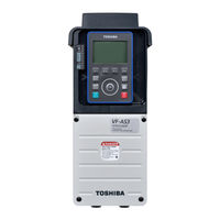
Toshiba TOSVERT VF-MB1 Instruction Manual (350 pages)
Industrial Inverter For 3-phase induction motors
Brand:
Toshiba
| Category:
Inverter
| Size: 6.18 MB
Table of Contents
Industrial Inverter
1
Safety Precautions
3
Maintenance and Inspection
8
Table of Contents
10
1 Read First
14
Check Product Purchase
14
Contents of the Product
15
Names and Functions
16
Notes on the Application
28
Installation Environment
35
2 Connection
40
Cautions on Wiring
40
Standard Connections
42
Standard Connection Diagram
43
Description of Terminals
45
Control Circuit Terminals
46
3 Operations
52
How to Set the Setup Menu
53
Simplified Operation of the VF-MB1
55
Frequency Setting
59
How to Operate the VF-MB1
60
Meter Setting and Adjustment
64
Setting the Electronic Thermal
67
Preset-Speed Operation (Speeds in 15 Steps
75
4 Setting Parameters
78
Setting and Display Modes
78
How to Set Parameters
80
Functions Useful in Searching for a Parameter or Changing a Parameter Setting
84
Checking the Region Settings Selection
90
EASY Key Function
91
5 Main Parameters
95
Searching for Changes Using the History Function
95
Setting a Parameter Using the Guidance Function
96
Selecting Inverter Overload Characteristic
98
Setting Acceleration/Deceleration Time
99
Increasing Starting Torque
101
Selection of Operation Mode
104
Meter Setting and Adjustment
108
Forward/Reverse Run Selection (Panel Keypad
108
Maximum Frequency
109
Upper Limit and Lower Limit Frequencies
110
Base Frequency
111
Selecting Control Mode
112
Manual Torque Boost - Increasing Torque Boost at Low Speeds
119
Setting the Electronic Thermal
119
Preset-Speed Operation (Speeds in 15 Steps
119
Process Input Value of PID Control
120
Default Setting
120
Checking the Region Setting Selection
120
EASY Key Mode Selection
120
Searching for and Resetting Changed Parameters
120
6 Other Parameters
121
Input/Output Parameters
121
Input Signal Selection
124
Terminal Function Selection
127
Modifying Input Terminal Functions
128
Modifying Output Terminal Functions
128
Basic Parameters 2
130
V/F 5-Point Setting
132
Frequency Priority Selection
132
Parameter Setting
133
Setting Frequency Command Characteristics
134
Fine Adjustment of Frequency Setting Signal
140
Operation Frequency
142
Starting Frequency
142
DC Braking
144
Motor Shaft Fixing Control
145
Time Limit for Lower-Limit Frequency Operation
146
Jog Run Mode
147
Jump Frequency - Avoiding Resonant Frequencies
149
Preset-Speed Frequencies
150
Bumpless Operation
150
PWM Carrier Frequency
152
Trip-Less Intensification
156
Retry Function
162
Avoiding Overvoltage Tripping
167
Droop Control
170
Light-Load High-Speed Operation Function
172
Braking Function
172
Acceleration/Deceleration Suspend Function
176
PID Control
178
Setting Motor Constants
184
Torque Limit
190
Power Running Stall Continuous Trip Detection Time
193
Acceleration/Deceleration Time 2 and 3
195
Protection Functions
200
Setting of Stall Prevention Level
200
Emergency Stop
202
Output Phase Failure Detection
203
Cooling Fan Control Selection
208
Cumulative Operation Time Alarm Setting
209
Undervoltage Trip
209
Forced Fire-Speed Control Function
214
Override
215
Analog Input Terminal Function Selection
218
Adjustment Parameters
219
Pulse Train Output for Meters
219
Operation Panel Parameter
222
Prohibition of Key Operations and Parameter Settings
222
Operation Example
229
Canceling the Operation Command
232
Selection of Operation Panel Stop Pattern
233
Tracing Functions
234
Integrating Wattmeter
238
Parameter Registration to Easy Setting Mode
238
Communication Function
239
Free Notes
246
Permanent Magnet Motors
247
Open Network Option
247
Traverse Function
248
Logic Sequence Function
248
7 Operations with External Signal
249
Operating External Signals
249
Applied Operations by an I/O Signal (Operation from the Terminal Block
250
Speed Instruction (Analog Signal) Settings from External Devices
261
8 Monitoring the Operation Status
265
Flow of Status Monitor Mode
265
Status Monitor Mode
266
Status Monitor under Normal Conditions
266
Display of Detailed Information on a Past Trip
268
Display of Trip Information
270
Trip Code Display
270
9 Measures to Satisfy the Standards
275
How to Cope with the CE Directive
275
Measures to Satisfy the Emc Directive
276
Compliance with UL Standard and CSA Standard
280
Motor Thermal Protection
281
Compliance with Safety Standards
282
Compliance with ATEX Applications
282
10 Peripheral Devices
283
Selection of Wiring Materials and Devices
283
Installation of a Magnetic Contactor
285
Installation of an Overload Relay
286
Optional External Devices
287
11 Table of Parameters and Data
289
Frequency Setting Parameter
289
Basic Parameters
289
Extended Parameters
292
Basic Parameter
295
Default Settings by Inverter Rating
318
Default Settings by Setup Menu
318
Input Terminal Function
319
Output Terminal Function
323
Unchangeable Parameters in Running
328
12 Specifications
329
Models and Their Standard Specifications
329
Outside Dimensions and Mass
332
13 Before Making a Service Call - Trip Information and Remedies
334
Trip Causes/Warnings and Remedies
334
Restoring the Inverter from a Trip
340
If the Motor Does Not Run While no Trip Message Is Displayed
341
How to Determine the Causes of Other Problems
342
14 Inspection and Maintenance
343
Regular Inspection
343
Check Points
344
Periodical Inspection
344
Check Items
345
Making a Call for Servicing
347
Keeping the Inverter in Storage
347
15 Warranty
348
16 Disposal of the Inverter
349
Advertisement
Toshiba TOSVERT VF-MB1 Manual (69 pages)
Brand:
Toshiba
| Category:
Inverter
| Size: 1.77 MB
Table of Contents
Table of Contents
4
Product Version and Esi File
6
Overview
7
Specification
7
Names and Functions
9
Outline
9
RJ45 Connector Pin Layout
10
Status Indicator
11
LED on the Option
11
Labels on the Inverter (Only for the VF-AS3)
12
Hardware Setup
14
Mounting and Removing
14
Mounting and Removing of Option for VF-MB1
14
Mounting and Removing of Option for VF-S15
14
Mounting and Removing of Option for VF-AS3
14
Parameters
15
Communication Parameters
15
Communication Parameters for IPE003Z
16
The Details of the Parameter Setting
19
Network Error Detection (C100 - C103)
19
Communication Object
20
Communication Profile
20
RPDO: Receive PDO
21
TPDO: Transmit PDO
22
TOSHIBA Drive Profile
23
Application Profile (Cia402)
24
Abort Code (Cia 301)
25
Running by Toshiba Drive Profile
26
TOSHIBA Drive Profile
26
Fa06 : 0X2A06 (Communication Command1)
29
Fa23 : 0X2A23 (Communication Command 2)
31
Fa07 : 0X2A07 (Frequency Reference from Internal Option)
33
Fa33 : 0X2A33 (Torque Command) (Only for the VF-AS3)
33
Fa50 : 0X2A50 (Terminal Output Data from Communication)
33
Fa51 : 0X2A51(Analog Output (FM) Data from Communication)
34
Fa52 : 0X2A52(Terminal am Output Data) (Only for the VF-AS3)
34
F441 : 0X2441 (Power Running Torque Limit Level 1)(Only for the VF-AS3)
34
F443 : 0X2443 (Regenerative Torque Limit Level 1)(Only for the VF-AS3)
34
F460 : 0X2460 (Speed Control Response 1)(Only for the VF-AS3)
34
F461 : 0X2461 (Speed Control Stabilization Coefficient 1)(Only for the VF-AS3)
34
Fd01 : 0X2D01 (Inverter Operating Status 1 (Real Time))
35
Fd00 : 0X2D00 (Output Frequency (Real Time))
37
Fd03 : 0X2D03 (Output Current (Real Time))
37
Fe35:0X2E35, Fe36: 0X2E36, Fe37: 0X2E37 (Monitoring of the Analog Input)
38
Fe14 : 0X2E14 (Cumulative Run Time)
38
Fe40 :0X2E40 (Analog Output (FM))
38
Fe41 :0X2E41 (am Output Monitor) (Only for the VF-AS3)
38
Fc91 :0X2C91 (Alarm Code)
39
Fd06 : 0X2D06 (Input TB Status)
40
Fd07 : 0X2D07 (Output TB Status)
41
Running by Cia402 Drive Profile
42
Cia 402 Drive Profile
42
Object 0X6040: Controlword
43
Object 6041: Statusword
43
Cia402 State Chart
45
Information of Cia402 State
46
Object 0X6042: Vl_Target_Velocity
48
Object 0X6043: Vl_Velocity_Demand
48
Object 0X6044: Vl_Velocity_Actual_Value
48
Object 0X6046: Vl_Velocity_Min_Max_Amount
48
Object 0X6048: Vl_Velocity_Acceleration
49
Object 0X6049: Vl_Velocity_Deceleration
49
Object 0X604A: Vl_Velocity_Quick_Stop
49
Object 0X605A: Quick Stop Option Code
50
Object 0X6060: Mode of Operation
51
Object 0X6061: Mode of Operation Display
51
Object 0X6502: Supported Drive Mode
51
Object 603F: Error Code
52
Ethercat State Machine (Esm)
54
Example:vf-Mb1 with Twincat
56
Plc-Configuration
56
Hardware
56
Twincat ® Software Installation
56
ESI File (Ethercat Slave Information)
56
VF-MB1 Configuration
56
System Manager: Declare Your Computer on Ethernet Network
57
System Manager: Install the Master
58
System Manager - Install the Slave: MB1 in "PLC- Configuration
60
PLC - Control: Initialization
61
PLC - Control: Declare the Variables
62
System Manager - Append PLC Project
63
PLC - Control: New Compilation
65
System Manager: Activate Configuration
65
PLC - Control: Run
65
PLC - Control: Start and Stop the Motor
65
PLC - Control: Add a Library for Other Services
66
Method of Add the Pdos
67
Toshiba TOSVERT VF-MB1 Function Manual (80 pages)
Brand:
Toshiba
| Category:
Inverter
| Size: 2.2 MB
Table of Contents
Table of Contents
2
Introduction
4
Combination of Product Version and GSDML File
9
Overview
10
Specification
10
Profinet
11
Modbus TCP
11
PROFINET and Ethernet Features
11
Web Server
11
LED Indicator
12
Diagnostic (PROFINET Service)
15
Hardware Setup
16
Mounting and Removing
16
Wiring
20
Installation Topology
21
Parameters
22
Communication Parameters
22
Communication Parameters for PROFINET
25
The Details of the Parameter Setting
28
Profidrive Profile
30
Telegram 1: Profidrive
30
STW Control Word Data
31
ZSW Status Word Data
32
State Machine
34
Vendor Specification Profile
36
Telegram 100: Vendor Specific
38
Telegram 101: Vendor Specific
38
Telegram 102: Vendor Specific
39
How to Use the PZD1 to 6
40
The Overview of the VF-S15/AS3/MB1 Parameter
41
Access to the Profidrive Parameter
54
Profidrive Parameter (PNU)
55
Access to Inverter Parameter
57
Profidrive Acyclic Parameter Access
59
Example1. Read the Profidrive Parameter
59
Example2. Read the Inverter Parameter
60
Example3. Change the Inverter Parameter
61
Code Table for Acyclic Communication
62
Modbus TCP
63
Header Format
63
Setting of Unit ID
63
List of Modbus Functions Supported
63
03 (0X03) Read Holding Registers" Function
64
06 (0X06) Write Single Register" Function
65
16 (0X10) Write Multiple Registers" Function
66
43 (0X2B) Read Device Identification" Function
67
Web Server
69
Access to the Web Server
69
Web Pages Structure
71
Drive Monitor (Main Menu: Monitoring)
71
Drive Parameters (Main Menu: Monitoring)
73
Network Parameters (Main Menu: Network Setup)
74
Administration (Main Menu: Network Setup)
75
TCP/IP Statistics (Main Menu: Diagnostics)
76
Modbus Statistics (Main Menu: Diagnostics)
76
Activation of Java7
77
Advertisement
Toshiba TOSVERT VF-MB1 Manual (45 pages)
Using CANopen communication function
Brand:
Toshiba
| Category:
Inverter
| Size: 0.64 MB
Table of Contents
Table of Contents
3
1 Scope
5
Overview
5
2 Names and Functions of Main Parts
5
Name of Main Parts
5
LED Indicator (Cia 303-3)
6
CAN RUN LED Indicator
6
CAN ERR LED Indicator
6
Command & Setpoint Selection (Local/Remote)
7
Cable Specification
7
Network Configuration
8
Bus Cable Length (Cia 303-1)
9
Example of SCAN Time
10
3 Parameters
11
Command and Freq. Reference Setting
11
Communication Parameters
12
4 Communication Object
16
Communication Profile (DS 301)
16
Communication Profile (1000 to 11Ffh)
16
SDO Sever Object
17
PDO Object
18
RPDO Object
18
TPDO Object
20
Manufacturer Specific Profile
21
Device Profile (Cia 402)
22
5 Drive Profile
23
Velocity Mode Object
23
Object 603Fh: Error Code
24
Object 6040H: Controlword
26
Object 6041: Statusword
28
Object 6042: Vl_Target_Velocity
28
Object 6043H: Vl_Velocity_Demand
28
Object 6044: Vl_Velocity_Actual_Value
28
Object 6046: Vl_Velocity_Min_Max_Amount
29
Object 6048H: Vl_Velocity_Acceleration
29
Object 6049: Vl_Velocity_Deceleration
29
Object 604A: Vl_Velocity_Quick_Stop
29
Object 605A: Quick Stop Option Code
29
Object 6060: Modes of Operation
30
Object 6061: Modes of Operation Display
30
Object 6502: Supported Drive Mode
30
6 Control from Canopen Network
31
NMT State Machine
31
SDO Communication
31
Read Object (Upload Object)
32
Write Object (Download Object)
32
Abort Code
33
PDO Communication
34
Txpdo and Rxpdo Communication Type
34
RTR (Remote Transfer Request) Communication
35
SYNC Communication
35
Emergency Object
35
Communication Disconnection Detection Function
36
Heartbeat Consumer
36
Heartbeat Producer
36
Node Guarding
36
NMT Boot-Up
37
7 Example Communication
38
Asynchlonous Communication
38
SYNC Communication
40
8 Specifications
42
Data and Operating Specification
42
Canopen Device Specification
42
Connecting of Canopen Communication Option
43
Toshiba TOSVERT VF-MB1 Function Manual (49 pages)
TOSVERT VF-MB1/S15 series EtherCAT option unit IPE003Z
Brand:
Toshiba
| Category:
Inverter
| Size: 0.99 MB
Table of Contents
Table of Contents
4
1 Overview
6
Communication and Services
6
2 Names and Functions
7
Outline
7
RJ45 Connector Pin Layout
8
LED Indicator
9
3 Parameters
10
Communication Parameters
10
Communication Parameters for IPE003Z
10
The Details of the Parameter Setting
13
Network Error Detection (C100 - C103)
13
4 Communication Object
14
Communication Profile
14
RPDO: Receive PDO
15
TPDO: Transmit PDO
15
MB1/S15 Specific Profile
15
Application Profile (Cia402)
16
Abort Code (Cia 301)
17
5 Drive Profile
18
Cia 402 Drive Profile
18
TOSHIBA Drive Profile
18
6 Cia ® 402 - Iec61800-7 Functional Profile
25
Velocity Mode Object
25
Cia 402 Profile
25
TOSHIBA Drive Profile
26
Object 0X6040: Controlword
27
Object 6041: Statusword
27
Cia402 State Chart
29
Object 0X6042: Vl_Target_Velocity
31
Object 0X6043: Vl_Velocity_Demand
31
Object 0X6044: Vl_Velocity_Actual_Value
31
Object 0X6046: Vl_Velocity_Min_Max_Amount
31
Object 0X6048: Vl_Velocity_Acceleration
32
Object 0X6049: Vl_Velocity_Deceleration
32
Object 0X604A: Vl_Velocity_Quick_Stop
32
Object 0X605A: Quick Stop Option Code
32
Object 0X6060: Mode of Operation
33
Object 0X6061: Mode of Operation Display
33
Object 0X6502: Supported Drive Mode
33
Object 603F: Error Code
34
7 Ethercat State Machine (Esm)
35
8 Example: Vf-Mb1 with Twincat "Plc - Configuration
37
Hardware
37
Twincat Software Installation
37
ESI File (Ethercat Slave Information)
37
MB1 Configuration
37
System Manager: Declare Your Computer on Ethernet Network
38
System Manager: Install the Master
39
System Manager - Install the Slave: MB1 in "PLC- Configuration
41
PLC - Control: Initialization
42
PLC - Control: Declare the Variables
43
System Manager - Append PLC Project
44
PLC - Control: New Compilation
46
System Manager: Activate Configuration
46
PLC - Control: Start and Stop the Motor
46
PLC - Control: Add a Library for Other Services
47
Method of Add the Pdos
48
Toshiba TOSVERT VF-MB1 Function Manual (48 pages)
Brand:
Toshiba
| Category:
Computer Hardware
| Size: 1.74 MB
Table of Contents
Table of Contents
2
Introduction
3
Product Version
8
Overview
9
Specification
9
Connection Information
10
Exterior Features
10
Status Indicator
11
Hardware Setup
12
Mounting and Removing
12
VF-MB1/S15/AS3 Communication Parameters
13
Profidrive Profile
14
Telegram 1: Profidrive
14
STW Control Word Data
15
State Machine
18
Access to the PROFIBUS Parameter
20
PROFIBUS Parameter (PNU)
21
Access to VF-MB1/S15/AS3 Parameter
24
Vendor Spec. Profile
26
Telegram 100: Vendor Specific
27
Telegram 101: Vendor Specific
28
Telegram 102: Vendor Specific
28
How to Use
29
The Overview of the VF-MB1/S15/AS3 Parameter
30
Diagnostic
40
Profidrive Acyclic Parameter Access
41
Example1. Read the Profidrive Parameter
42
Example 2. Change the Profidrive Parameter
43
Example 3. Read the VF-MB1/S15/AS3 Parameter
44
Example 4. Change the VF-MB1/S15/AS3 Parameter
45
PROFIBUS Local/Remote Operation
46
GSD File
46
Appendix
47
Toshiba TOSVERT VF-MB1 Manual (33 pages)
PROFIBUS-DP Option Function
Brand:
Toshiba
| Category:
DC Drives
| Size: 0.45 MB
Table of Contents
Table of Contents
2
1 Introduction
3
2 Connection Information
4
Exterior Features
4
Status Indicator
5
VF-MB1 Communication Parameters
6
3 Profile
7
Telegram
7
STW Control Word Data
8
ZSW Status Word Data
9
State Machine
11
Access to the PROFIBUS Parameter
13
PROFIBUS Parameter (PNU)
14
Access to VF-MB1 Parameter
16
4 Vendor Spec. Profile
18
How to Use
19
The Overview of the VF-MB1 Parameter
20
5 Diagnostic
26
6 DP-V1 Function
27
Example1. Read the Profidrive Parameter
28
Example 2. Change the Profidrive Parameter
29
Example 3. Read the VF-MB1 Parameter
30
Example 4. Change the VF-MB1 Parameter
31
PROFIBUS Local/Remote Operation
32
7 GSD File
32
8 Appendix
33
Toshiba TOSVERT VF-MB1 Instruction Manual (6 pages)
Traverse control For textile machines
Brand:
Toshiba
| Category:
Control Unit
| Size: 0.22 MB
Advertisement
Related Products
Toshiba TOSVERT VF-FS1 Series
Toshiba VFA7-2370P1
Toshiba VFS11S-2015PL
Toshiba VFS11-2037PM
Toshiba TOSVERT VFS15-2110PM-W
Toshiba TOSVERT VFAS1-4110PL
Toshiba TOSVERT VFAS1-4150PL
Toshiba VFS11S-2004PM
Toshiba VFS11S-6075P
Toshiba TOSVERT VFAS1-4185PL
Toshiba Categories
Laptop
Air Conditioner
TV
LCD TV
All in One Printer
More Toshiba Manuals
Login
Sign In
OR
Sign in with Facebook
Sign in with Google
Upload manual
Upload from disk
Upload from URL