Sign In
Upload
Manuals
Brands
SUZUKI Manuals
Motorcycle
GSX-1300R
SUZUKI GSX-1300R Manuals
Manuals and User Guides for SUZUKI GSX-1300R. We have
5
SUZUKI GSX-1300R manuals available for free PDF download: Manual, Owner's Manual, Supplementary Service Manual, Service Bulletin
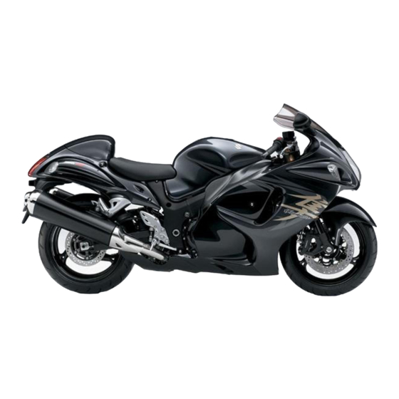
Suzuki GSX-1300R Manual (663 pages)
Suzuki GSX1300R Motorcycle
Brand:
Suzuki
| Category:
Motorcycle
| Size: 36 MB
Table of Contents
Section 1 Engine
67
General Information
15
Front Suspension
26
Maintenance and Lubrication
31
Scheduled Maintenance
31
Exterior Parts
34
Service Data
55
Table of Contents
67
Engine General Information and Diagnosis
72
Fi System Parts Location
77
Engine General Information and
83
Show Data When Trouble
85
DTC Table
91
Malfunction Code and Defective Condition
96
Malfunction
96
DTC "C12" (P0335): CKP Sensor Circuit Malfunction
101
DTC "C13" (P0105-H/L): IAP Sensor Circuit Malfunction
104
DTC "C14" (P0120-H/L): TP Sensor Circuit Malfunction
111
DTC "C15" (P0115-H/L): ECT Sensor Circuit Malfunction
118
DTC "C21" (P0110-H/L): IAT Sensor Circuit Malfunction
123
DTC "C22" (P01450-H/L): AP Sensor Circuit Malfunction
128
DTC "C23" (P1651-H/L): to Sensor Circuit Malfunction
135
DTC "C24" (P0351), "C25" (P0352), "C26" (P0353) or "C27" (P0354): Ignition System Malfunction
142
DTC "C28" (P1655): Secondary Throttle Valve Actuator (STVA) Malfunction
142
DTC "C29" (P1654-H/L): Secondary Throttle Position Sensor (STPS) Circuit Malfunction
146
DTC "C31" (P0705): GP Switch Circuit Malfunction
153
DTC "C32" (P0201), "C33" (P0202), "C34" (P0203) or "C35" (P0204): Primary Fuel Injector Circuit Malfunction
155
DTC "C36" (P1764), "C37" (P1765), "C38" (P1766) or "C39" (P1767): Secondary Fuel Injector Circuit Malfunction
159
DTC "C40" (P0505 / P0506 / P0507): ISC Valve Circuit Malfunction
163
DTC "C41" (P0230-H/L): FP Relay Circuit Malfunction
168
DTC "C41" (P2505): ECM Power Input Signal Malfunction
171
DTC "C42" (P1650): IG Switch Circuit Malfunction
173
DTC "C44" (P0130/P0135): HO2 Sensor (HO2S) Circuit Malfunction
173
DTC "C49" (P1656): PAIR Control Solenoid Valve Circuit Malfunction
179
DTC "C60" (P0480): Cooling Fan Relay Circuit Malfunction
183
DTC "C62" (P0443): EVAP System Purge Control Solenoid Valve Circuit Malfunction (E-33 Only)
186
Specifications
189
Service Data
189
Exhaust Emission Control System Description
194
Noise Emission Control System Description
197
Evaporative Emission Control System Diagram (Only for
198
Schematic and Routing Diagram
199
EVAP Canister Hose Routing Diagram
199
Repair Instructions
200
Heated Oxygen Sensor (HO2S) Removal and Installation
200
Heated Oxygen Sensor (HO2S) Inspection
200
PAIR Reed Valve Removal and Installation
200
PAIR Control Solenoid Valve Removal and Installation
201
PAIR System Inspection
202
Crankcase Breather (PCV) Hose Inspection
203
Crankcase Breather (PCV) Hose / Reed Valve / Cover Removal and Installation
203
Crankcase Breather (PCV) Cover Inspection
204
Evaporative Emission Control System Removal and Installation (Only for
205
Evaporative Emission Control System Inspection (for E-33 Only)
206
Specifications
208
Service Data
208
Tightening Torque Specifications
208
Special Tools and Equipment
209
Special Tool
209
Recommended Service Material
209
Engine Electrical Devices
210
Precautions
210
Precautions for Engine Electrical Device
210
Component Location
210
Engine Electrical Components Location
210
Diagnostic Information and Procedures
210
Engine Symptom Diagnosis
210
Repair Instructions
211
ECM Removal and Installation
211
CMP Sensor Inspection
211
CMP Sensor Removal and Installation
211
CKP Sensor Inspection
211
CKP Sensor Removal and Installation
211
IAP Sensor Inspection
212
IAP Sensor Removal and Installation
212
TP Sensor Inspection
212
TP Sensor Removal and Installation
212
TP Sensor Adjustment
213
ECT Sensor Removal and Installation
214
ECT Sensor Inspection
214
IAT Sensor Removal and Installation
215
IAT Sensor Inspection
215
AP Sensor Inspection
215
AP Sensor Removal and Installation
215
TO Sensor Inspection
215
TO Sensor Removal and Installation
216
STP Sensor Inspection
216
STP Sensor Adjustment
216
STP Sensor Removal and Installation
217
STV Actuator Inspection
218
STV Actuator Removal and Installation
218
ISC Valve Inspection
218
ISC Valve Removal and Installation
218
ISC Valve Preset and Opening Initialization
218
HO2 Sensor Inspection
219
HO2 Sensor Removal and Installation
219
GP Switch Inspection
219
GP Switch Removal and Installation
219
Specifications
220
Service Data
220
Tightening Torque Specifications
221
Special Tools and Equipment
221
Recommended Service Material
221
Special Tool
221
Engine Mechanical
222
Schematic and Routing Diagram
222
Camshaft and Sprocket Assembly Diagram
222
Throttle Cable Routing Diagram
223
Diagnostic Information and Procedures
224
Engine Mechanical Symptom Diagnosis
224
Compression Pressure Check
224
Repair Instructions
225
Engine Components Removable with the Engine in Place
225
Air Cleaner Element Removal and Installation
227
Air Cleaner Box Removal and Installation
227
Air Cleaner Element Inspection and Cleaning
228
Throttle Cable Removal and Installation
228
Throttle Cable Inspection
228
Throttle Cable Play Inspection and Adjustment
228
Throttle Body Components
229
Throttle Body Construction
230
Throttle Body Removal and Installation
231
Throttle Body Disassembly and Assembly
233
Throttle Body Inspection and Cleaning
237
ISC Valve Visual Inspection
237
Throttle Valve Synchronization
237
ISC Valve Reset
239
TP Reset
240
Engine Assembly Removal
240
Engine Assembly Installation
245
Engine Top Side Disassembly
248
Engine Top Side Assembly
252
Camshaft Inspection
263
Camshaft Sprocket / Bearing Inspection
265
Cam Chain Tension Adjuster Inspection
266
Cam Chain Guide Removal and Installation
267
Cam Chain Guide Inspection
267
Cam Chain Tensioner Inspection
267
Cylinder Head Disassembly and Assembly
268
Cylinder Head Related Parts Inspection
273
Valve Guide Replacement
277
Valve Seat Repair
278
Cylinder Disassembly and Assembly
279
Cylinder Inspection
280
Piston Ring Removal and Installation
281
Piston and Piston Ring Inspection
282
Engine Bottom Side Disassembly
284
Engine Bottom Side Assembly
292
Crank Balancer Disassembly and Assembly
309
Crank Balancer Inspection
310
Conrod Removal and Installation
310
Conrod and Crankshaft Inspection
312
Conrod Crank Pin Bearing Inspection and Selection
313
Crankshaft Journal Bearing Inspection and Selection
315
Crankshaft Thrust Clearance Inspection and Selection
317
Specifications
319
Service Data
319
Tightening Torque Specifications
321
Special Tools and Equipment
322
Recommended Service Material
322
Special Tool
323
Engine Lubrication System
326
Precautions
326
Precautions for Engine Oil
326
Schematic and Routing Diagram
326
Engine Lubrication System Chart Diagram
326
Oil Pan
327
Engine Lubrication Circuit Diagram
328
Diagnostic Information and Procedures
330
Engine Lubrication Symptom Diagnosis
330
Oil Pressure Check
330
Repair Instructions
331
Engine Oil and Filter Replacement
331
Engine Oil Level Inspection
331
Oil Pan / Oil Strainer / Oil Pressure Regulator
331
Removal and Installation
331
Oil Pressure Regulator / Oil Strainer Inspection
332
Oil Cooler / Oil Cooler Hose Inspection and Cleaning
333
Oil Cooler / Oil Cooler Hose Removal and Installation
333
Oil Pressure Switch Removal and Installation
334
Oil Pressure Switch Inspection
335
Oil Jet / Oil Gallery Jet Removal and Installation
335
Oil Jet / Oil Gallery Jet Inspection
337
Oil Pump Removal and Installation
337
Oil Pump Inspection
338
Specifications
339
Service Data
339
Tightening Torque Specifications
339
Special Tools and Equipment
340
Recommended Service Material
340
Special Tool
340
Engine Cooling System
341
Precautions
341
Precautions for Engine Cooling System
341
Precautions for Engine Coolant
341
General Description
341
Engine Coolant Description
342
Schematic and Routing Diagram
342
Cooling Circuit Diagram
342
Water Hose Routing Diagram
343
Diagnostic Information and Procedures
344
Engine Cooling Symptom Diagnosis
344
Repair Instructions
344
Cooling Circuit Inspection
344
Radiator Cap Inspection
345
Radiator Inspection and Cleaning
345
Radiator / Cooling Fan Motor Removal and Installation
346
Water Hose Inspection
347
Water Hose Removal and Installation
348
Radiator Reservoir Tank Removal and Installation
348
Radiator Reservoir Tank Inspection
348
Cooling Fan Inspection
348
Cooling Fan Relay Inspection
349
ECT Sensor Removal and Installation
349
ECT Sensor Inspection
349
Thermostat Cover / Thermostat Removal and Installation
349
Thermostat Inspection
350
Water Pump Components
351
Water Pump Construction
352
Water Pump Removal and Installation
352
Water Pump Disassembly and Assembly
353
Water Pump Related Parts Inspection
356
Specifications
357
Service Data
357
Tightening Torque Specifications
358
Special Tools and Equipment
358
Recommended Service Material
358
Special Tool
358
Fuel System
359
Precautions
359
Precautions for Fuel System
359
General Description
360
Fuel Injection System Description
360
Schematic and Routing Diagram
361
Fuel Tank Drain Hose and Breather Hose Routing Diagram
361
Diagnostic Information and Procedures
362
Fuel System Diagnosis
362
Repair Instructions
363
Fuel Pressure Inspection
363
Fuel Pump Inspection
364
Fuel Discharge Amount Inspection
364
Fuel Pump Relay Inspection
365
Fuel Hose Inspection
365
Fuel Level Gauge Inspection
365
Fuel Tank Construction
366
Fuel Tank Heat Shield Construction
367
Fuel Tank Removal and Installation
367
Fuel Pump Components
369
Fuel Pump Disassembly and Assembly
370
Fuel Mesh Filter Inspection and Cleaning
372
Fuel Injector / Fuel Delivery Pipe / T-Joint Removal and Installation
372
Fuel Injector Inspection and Cleaning
372
Specifications
373
Service Data
373
Tightening Torque Specifications
373
Special Tools and Equipment
374
Recommended Service Material
374
Special Tool
374
Ignition System
375
General Description
375
Immobilizer Description (for
375
Drive Mode Selector Description
376
Schematic and Routing Diagram
377
Ignition System Diagram
377
Ignition System Components Location
377
Diagnostic Information and Procedures
378
Ignition System Symptom Diagnosis
378
No Spark or Poor Spark
379
Repair Instructions
380
Ignition Coil / Plug Cap and Spark Plug Removal and Installation
380
Spark Plug Inspection and Cleaning
381
Ignition Coil / Plug Cap Inspection
381
CKP Sensor Inspection
384
CKP Sensor Removal and Installation
385
Engine Stop Switch Inspection
385
Ignition Switch Inspection
386
Ignition Switch Removal and Installation
386
Drive Mode Selector Inspection
387
Immobilizer Antenna Removal and Installation (for
388
Specifications
388
Service Data
388
Tightening Torque Specifications
388
Special Tools and Equipment
389
Recommended Service Material
389
Special Tool
389
Starting System
390
Schematic and Routing Diagram
390
Starting System Diagram
390
Component Location
390
Starting System Components Location
390
Diagnostic Information and Procedures
390
Starting System Symptom Diagnosis
390
Starter Motor will Not Run
391
Starter Motor Runs but Does Not Crank the Engine
391
Repair Instructions
392
Starter Motor Components
392
Starter Motor Removal and Installation
393
Starter Motor Disassembly and Assembly
393
Starter Motor Inspection
394
Starter Relay Removal and Installation
395
Starter Relay Inspection
396
Turn Signal / Side-Stand Relay Removal and Installation
396
Side-Stand / Ignition Interlock System Parts Inspection
397
Starter Torque Limiter / Starter Clutch Removal and Installation
399
Starter Torque Limiter Inspection
401
Starter Clutch Inspection
401
Starter Button Inspection
402
Specifications
402
Service Data
402
Tightening Torque Specifications
402
Special Tools and Equipment
403
Recommended Service Material
403
Special Tool
403
Charging System
404
Schematic and Routing Diagram
404
Charging System Diagram
404
Component Location
404
Charging System Components Location
404
Diagnostic Information and Procedures
404
Charging System Symptom Diagnosis
404
Battery Runs down Quickly
405
Repair Instructions
406
Battery Cushion Rubber Attachment Construction
406
Battery Current Leakage Inspection
407
Regulated Voltage Inspection
407
Generator Inspection
408
Generator Removal and Installation
409
Regulator / Rectifier Construction
412
Regulator / Rectifier Removal and Installation
413
Regulator / Rectifier Inspection
413
Battery Components
414
Battery Charging
414
Battery Removal and Installation
417
Battery Visual Inspection
417
Specifications
418
Service Data
418
Tightening Torque Specifications
418
Special Tools and Equipment
419
Recommended Service Material
419
Special Tool
419
Exhaust System
420
Precautions
420
Precautions for Exhaust System
420
Repair Instructions
421
Exhaust System Construction
421
Exhaust Pipe / Muffler Removal and Installation
422
Exhaust System Inspection
426
Tightening Torque Specifications
426
Special Tools and Equipment
427
Recommended Service Material
427
Section 2 Suspension
429
Precautions
430
Precautions for Suspension
430
Suspension General Diagnosis
431
Diagnostic Information and Procedures
431
Suspension and Wheel Symptom Diagnosis
431
Front Suspension
432
Repair Instructions
432
Front Fork Components
432
Front Fork Removal and Installation
433
Front Suspension Adjustment
436
Front Fork Disassembly and Assembly
437
Front Fork Parts Inspection
443
Specifications
444
Service Data
444
Tightening Torque Specifications
444
Special Tools and Equipment
445
Recommended Service Material
445
Special Tool
445
Rear Suspension
446
Repair Instructions
446
Rear Suspension Components
446
Rear Suspension Assembly Construction
447
Rear Shock Absorber / Cusion Lever Removal and Installation
448
Rear Suspension Inspection
449
Rear Shock Absorber Inspection
449
Rear Suspension Adjustment
449
Rear Shock Absorber Disposal
450
Cushion Lever Removal and Installation
451
Cushion Lever Inspection
451
Cushion Lever Bearing Removal and Installation
452
Swingarm / Cushion Rod Removal and Installation
453
Swingarm Related Parts Inspection
456
Swingarm Bearing Removal and Installation
457
Specifications
458
Service Data
458
Tightening Torque Specifications
458
Special Tools and Equipment
459
Recommended Service Material
459
Special Tool
459
Wheels and Tires
460
Precautions
460
Precautions for Wheel and Tire
460
Repair Instructions
461
Front Wheel Components
461
Front Wheel Assembly Construction
462
Front Wheel Assembly Removal and Installation
463
Front Wheel Related Parts Inspection
465
Front Wheel Dust Seal / Bearing Removal and Installation
466
Rear Wheel Components
468
Rear Wheel Assembly Construction
469
Rear Wheel Assembly Removal and Installation
470
Rear Wheel Related Parts Inspection
471
Rear Wheel Dust Seal / Bearing Removal and Installation
472
Tire Removal and Installation
474
Wheel / Tire / Air Valve Inspection and Cleaning
475
Air Valve Removal and Installation
476
Wheel Balance Check and Adjustment
477
Specifications
477
Service Data
477
Tightening Torque Specifications
478
Special Tools and Equipment
478
Recommended Service Material
478
Special Tool
478
Section 3 Driveline / Axle
481
Precautions
482
Precautions for Driveline / Axle
482
Diagnostic Information and Procedures
483
Drive Chain and Sprocket Symptom Diagnosis
483
Repair Instructions
483
Drive Chain Related Components
483
Engine Sprocket Removal and Installation
484
Rear Sprocket / Rear Sprocket Mounting Drum Removal and Installation
486
Drive Chain Related Parts Inspection
487
Sprocket Mounting Drum Dust Seal / Bearing Removal and Installation
487
Drive Chain Replacement
489
Drive Chain / Drive Train / Drive Shaft
483
Special Tools and Equipment
493
Recommended Service Material
493
Special Tool
494
Specifications
493
Service Data
493
Tightening Torque Specifications
493
Section 4 Brake
495
Precautions
496
Precautions for Brake System
496
Brake Fluid Information
496
Brake Control System and Diagnosis
497
Schematic and Routing Diagram
497
Front Brake Hose Routing Diagram
497
Rear Brake Hose Routing Diagram
498
Diagnostic Information and Procedures
499
Brake Symptom Diagnosis
499
Repair Instructions
499
Brake Pedal Height Inspection and Adjustment
499
Front Brake Light Switch Inspection
499
Rear Brake Light Switch Inspection
500
Rear Brake Light Switch Inspection and Adjustment
500
Brake Fluid Level Check
500
Brake Hose Inspection
500
Air Bleeding from Brake Fluid Circuit
500
Brake Fluid Replacement
502
Front Brake Hose Removal and Installation
504
Rear Brake Hose Removal and Installation
504
Front Brake Master Cylinder Components
505
Front Brake Master Cylinder Assembly Removal and Installation
506
Front Brake Master Cylinder / Brake Lever Disassembly and Assembly
507
Front Brake Master Cylinder Parts Inspection
508
Rear Brake Master Cylinder Components
509
Rear Brake Master Cylinder Assembly Removal and Installation
510
Rear Brake Master Cylinder Disassembly and Assembly
511
Rear Brake Master Cylinder Parts Inspection
512
Rear Brake Pedal Construction
513
Rear Brake Pedal Removal and Installation
513
Specifications
514
Service Data
514
Tightening Torque Specifications
514
Special Tools and Equipment
515
Recommended Service Material
515
Special Tool
515
Front Brakes
516
Repair Instructions
516
Front Brake Components
516
Front Brake Pad Inspection
517
Front Brake Pad Replacement
517
Front Brake Caliper Removal and Installation
518
Front Brake Caliper Disassembly and Assembly
519
Front Brake Caliper Parts Inspection
521
Front Brake Disc Removal and Installation
522
Front Brake Disc Inspection
522
Specifications
523
Service Data
523
Tightening Torque Specifications
523
Special Tools and Equipment
524
Recommended Service Material
524
Special Tool
524
Repair Instructions
525
Rear Brake Components
525
Rear Brake Pad Inspection
526
Rear Brake Pad Replacement
526
Rear Brake Caliper Removal and Installation
527
Rear Brake Caliper Disassembly and Assembly
528
Rear Brake Caliper Parts Inspection
530
Rear Brake Disc Removal and Installation
530
Rear Brake Disc Inspection
531
Rear Brakes
525
Specifications
532
Service Data
532
Tightening Torque Specifications
532
Special Tools and Equipment
533
Recommended Service Material
533
Special Tool
533
Section 5 Transmission / Transaxle
535
Precautions
536
Precautions for Transmission / Transaxle
536
Manual Transmission
537
Diagnostic Information and Procedures
537
Manual Transmission Symptom Diagnosis
537
Repair Instructions
538
Transmission Components
538
Transmission Removal
539
Transmission Installation
540
Transmission Construction
543
Countershaft Gear / Driveshaft Gear Disassembly and Assembly
543
Transmission Related Parts Inspection
546
Gear Position (GP) Switch Inspection
547
Gear Position (GP) Switch Removal and Installation
547
Gearshift Lever Construction
549
Gearshift Lever Removal and Installation
550
Gearshift Lever Height Inspection and Adjustment
550
Gearshift Shaft / Gearshift Cam Plate Components
550
Gearshift Shaft Construction
551
Gearshift Shaft / Gearshift Cam Plate Removal and Installation
552
Gearshift Linkage Inspection
553
Gearshift Shaft Oil Seal / Bearing Removal and Installation
553
Specifications
555
Service Data
555
Tightening Torque Specifications
555
Special Tools and Equipment
556
Recommended Service Material
556
Special Tool
556
Precautions
557
Precautions for Clutch System
557
Clutch Fluid (Brake Fluid) Information
557
Clutch
557
Schematic and Routing Diagram
558
Clutch Hose Routing Diagram
558
Diagnostic Information and Procedures
559
Clutch System Symptom Diagnosis
559
Repair Instructions
559
Clutch Lever Position Switch Inspection
559
Clutch Fluid Level Check
559
Clutch Hose Inspection
559
Air Bleeding from Clutch Fluid Circuit
560
Clutch Fluid Replacement
560
Clutch Hose Removal and Installation
561
Clutch Control System Components
562
Clutch Master Cylinder Assembly Removal and Installation
563
Clutch Master Cylinder / Clutch Lever Disassembly and Assembly
564
Clutch Master Cylinder Components Inspection
566
Clutch Release Cylinder / Push Rod Removal and Installation
566
Clutch Push Rod Inspection
568
Clutch Release Cylinder Disassembly and Assembly
568
Clutch Release Cylinder Inspection
568
Clutch Components
569
Clutch Removal
570
Clutch Installation
573
Clutch Parts Inspection
577
Specifications
579
Service Data
579
Tightening Torque Specifications
579
Special Tools and Equipment
580
Recommended Service Material
580
Special Tool
580
Section 6 Steering
581
Precautions
582
Precautions for Steering
582
Steering General Diagnosis
583
Diagnostic Information and Procedures
583
Steering Symptom Diagnosis
583
Steering / Handlebar
584
Repair Instructions
584
Handlebar Components
584
Handlebar Construction
585
Handlebar Removal and Installation
586
Handlebars Inspection
587
Steering Components
588
Steering Damper Construction
589
Steering Removal and Installation
589
Steering Related Parts Inspection
593
Steering System Inspection
593
Steering Stem Bearing Removal and Installation
594
Steering Tension Adjustment
595
Special Tools and Equipment
596
Recommended Service Material
596
Special Tool
597
Specifications
596
Tightening Torque Specifications
596
Section 9 Body and Accessories
599
Component Location
601
Electrical Components Location
601
Precautions
601
Precautions for Electrical System
601
Wiring Systems
602
Schematic and Routing Diagram
602
Wiring Diagram
602
Wiring Harness Routing Diagram
606
Special Tools and Equipment
610
Recommended Service Material
610
Specifications
610
Service Data
610
Tightening Torque Specifications
610
Repair Instructions
611
Headlight Components
611
Headlight Removal and Installation
612
Headlight Bulb and Position Light Bulb Replacement
612
Headlight Beam Adjustment
613
Front Turn Signal Light Components
613
Front Turn Signal Light Removal and Installation
614
Front Turn Signal Light Bulb Replacement
614
Rear Lighting System Construction
615
Rear Combination Light Removal and Installation
615
Rear Combination Light Replacement
616
License Plate Light Components
616
License Plate Light Removal and Installation
617
License Plate Light Bulb Replacement
617
Rear Turn Signal Light Components
618
Rear Turn Signal Light Removal and Installation
618
Rear Turn Signal Light Bulb Replacement
618
Reflex Reflector Construction
619
Turn Signal / Side-Stand Relay Inspection
619
Turn Signal / Side-Stand Relay Removal and Installation
619
Hazard Switch Inspection
620
Turn Signal Switch Inspection
620
Passing Light Switch Inspection
621
Dimmer Switch Inspection
621
Lighting Systems
611
Special Tools and Equipment
622
Recommended Service Material
622
Special Tool
622
Specifications
622
Service Data
622
Tightening Torque Specifications
622
Combination Meter / Fuel Meter / Horn
623
General Description
623
Combination Meter System Description
623
Repair Instructions
624
Combination Meter Components
624
Combination Meter Removal and Installation
624
Combination Meter Disassembly and Assembly
625
Combination Meter Inspection
625
Engine Coolant Temperature Meter and Indicator Light Inspection
626
ECT Sensor Removal and Installation
627
Fuel Meter Inspection
627
Fuel Level Gauge Inspection
628
Speedometer Inspection
628
Speed Sensor Removal and Installation
628
Speed Sensor Inspection
629
Oil Pressure Indicator Inspection
629
Oil Pressure Switch Removal and Installation
629
Oil Pressure Switch Inspection
630
Ignition Switch Inspection
630
Ignition Switch Removal and Installation
630
Horn Inspection
631
Horn Removal and Installation
631
Specifications
632
Service Data
632
Special Tools and Equipment
632
Schematic and Routing Diagram
633
Seat Lock Cable Routing Diagram
633
Exterior Parts
633
Repair Instructions
634
Exterior Parts Construction
634
Rear under Cowling Head Shield Attachment
635
Intake Cover Protection Tape Attachment
635
Inner under Cowling Cushion Attachment
636
Under Cowling Heat Shield Attachment
636
Pillion Rider Handlebar Construction
637
Panel Cushion Attachment
638
Rear Fender Construction
639
Frame Cover Construction
640
Cowling Cushion Attachment
641
Flame Cover Cushion Attachment
642
Mudguard Construction
643
Rear Fender Cushion Attachment
644
Body Cowling Cover Cushion Attachment
644
Fastener Removal and Installation
645
Exterior Parts Removal and Installation
646
Specifications
654
Tightening Torque Specifications
654
Special Tools and Equipment
654
Recommended Service Material
654
Special Tool
654
Body Structure
655
Repair Instructions
655
Body Frame Construction
655
Front Footrest Bracket Construction
656
Side-Stand Construction
657
Pillion Footrest Bracket Construction
657
Footrest Construction
658
Side-Stand Removal and Installation
659
Specifications
659
Tightening Torque Specifications
659
Special Tools and Equipment
659
Recommended Service Material
659
Advertisement
Suzuki GSX-1300R Owner's Manual (143 pages)
Brand:
Suzuki
| Category:
Motorcycle
| Size: 1 MB
Table of Contents
Table of Contents
5
The Sport of Motorcycling
7
Most Accidents Can be Avoided
8
If You Don't Have a Helmet, Buy a Helmet and Wear It Every Time You Ride
8
If a Collision Is Imminent, Do Something
9
Special Situations Require Special Care
10
Know Your Limits
10
Accessories and Loading
11
Inspection before Riding
11
Practice Away from Traffic
11
Be Extra Safety-Conscious on Bad Weather Days
11
Carrying a Passenger
12
Motorcycle Safety Foundation's "Riding Tips and Practice Guide" Handbook (for Owners in Usa)
12
Be Street Smart
12
Conclusion
12
Fuel, Engine Oil and Coolant Recommendations
13
Controls, Equipment and Adjustments
19
Location of Parts
20
Ignition Switch
23
Key
23
Instrument Panel
25
Left Handlebar
32
Right Handlebar
34
Fuel Tank Cap
37
Gearshift Lever
38
Rear Brake Pedal
38
Seat Lock and Helmet Holders
39
Side Stand
41
Suspension Adjustment
42
Seat Tail Cover
46
Break-In and Inspection before Riding
49
Riding Tips
53
Starting the Engine
54
Starting off
55
Using the Transmission
56
Riding on Hills
57
Stopping and Parking
57
Carrying a Passenger
59
Accessory Use and Motorcycle Loading
61
Inspection and Maintenance
65
Maintenance Schedule
66
Notice
66
Steering Damper Maintenance
69
Tools
69
Lubrication Points
70
Battery
71
Air Cleaner
72
Spark Plugs
75
Engine Oil
79
Engine Idle Speed Inspection
84
Throttle Cable Play
84
Fuel Hose
85
Clutch
86
Engine Coolant
87
Drive Chain
89
Brakes
93
Tires
98
Side Stand/Ignition Interlock Switch
102
Front Wheel Removal
103
Rear Wheel Removal
106
Light Bulb Replacement
108
Fuses
114
Troubleshooting
117
Storage Procedure and Motorcycle Cleaning
121
Storage Procedure
122
Procedure for Returning to Service
123
Corrosion Prevention
124
Motorcycle Cleaning
125
Inspection after Cleaning
127
Consumer Information
129
Emission Control Warranty
130
Reporting Safety Defects
130
Tampering with Noise Control System Prohibited
131
On-Board Motorcycle Computer Data Information
132
Serial Number Location
133
Location of Labels
134
Specifications
136
Suzuki GSX-1300R Owner's Manual (47 pages)
Brand:
Suzuki
| Category:
Motorcycle
| Size: 1 MB
Table of Contents
Break-In
2
Warning/Caution/Note
2
Foreword
3
Table of Contents
3
Modification
4
Safe Riding Recommendation for Motorcycle Riders
5
Wear a Helmet
5
Serial Number Location
5
Ride Defensively
5
Location of Parts
6
Controls
7
Key/Ignition Switch
7
"OFF/ON" Position
7
"Lock" Position
7
Instrument Panel
8
Fuel Meter
8
Low Fuel Indicator Light
8
Left Turn Signal Indicator Light
8
Clock/Fuel Injection System Indicator/Clock Mode
9
Speedometer
9
Coolant Temperature Meter
9
Neutral Indicator Light
9
Odometer/Trip Meter/Fuel Consumption Meter
10
Fuel Consumption Meter
10
High Beam Indicator Light
10
Left Handlebar
11
Clutch/Choke Lever
11
Clutch Lever Adjustment
11
Dimmer/Turn Signal Light Switch
11
Right Handlebar
12
Light Switch
12
Electric Starter Button
12
Throttle Grip
12
Fuel Tank Cap
13
Gearshift Lever
13
Rear Brake Pedal
13
Seat Lock and Helmet Holders
14
Front Seat
14
Rear Seat
14
Helmet Holders
14
Side Stand
15
Suspension Adjustment
15
Front Suspension
15
Spring Pre-Load Adjustment
15
Damping Force Adjustment
16
Rear Suspension
16
Suspension Setting
17
Fuel, Engine Oil and Coolant Recommendation
17
Gasoline/Ethanol
17
Gasoline/Methanol Blends
17
Engine Oil/Coolant
18
Break-In (Running-In)
18
Maximum Engine Speed Recommendation
18
Vary the Engine Speed
18
Avoid Constant Low Speed
19
Allow the Engine Oil to
19
Observe Your First and most Critical Service
19
Inspection before Riding
19
Riding Tips
20
Starting the Engine
20
When the Cold/Warm Engine Is Hard to Start
20
When the Engine Is Warm
20
Starting off
21
Using the Transmission
21
Shifting Up/Down Schedule
21
Riding on Hills
21
Stopping and Parking
22
Inspection and Maintenance
22
Maintenance Schedule
22
Maintenance Chart
23
Tools
23
Steering Damper Maintenance
23
Fairing Removal
24
Installation
24
Lubrication Points
24
Battery
25
Air Cleaner
25
Spark Plug
26
Removal
26
Inspection
27
Plug Replacement Guide
27
Fuel Line
28
Engine Oil Level Check
28
Engine Oil and Filter Change
28
To Adjust the Idle Speed
30
Throttle Cable Play
30
To Adjust the Cable Play
30
Clutch
31
Coolant Level
31
Changing the Coolant
31
Drive Chain Cleaning and Oiling
32
Drive Chain Adjustment
32
To Adjust the Drive Chain, Follow the Procedure below
33
Brake System
33
Brake Fluid
33
Brake Pad
34
Rear Brake Pedal Adjustment
35
Rear Brake Light Switch
35
Tire Pressure and Loading
35
Cold Tire Inflation Pressure
35
Tire Condition and Type
36
Side Stand/Ignition Interlock Switch
37
Front Wheel Removal
37
Rear Wheel Removal
38
Light Bulb Replacement
39
Headlight
39
High Beam
39
Low Beam
39
Headlight Beam Adjustment
40
Front Turn Signal Light
40
Rear Turn Signal Light
40
Brake Light/Taillight
41
License Plate Light
41
To Access the Fuses
41
Fuse List
42
Troubleshooting
42
Fuel Supply Check
42
Ignition System Check
42
Engine Stalling
43
Motorcycle Cleaning
43
Windshield Cleaning/Waxing the Motorcycle
43
Inspection after Cleaning
43
Advertisement
Suzuki GSX-1300R Supplementary Service Manual (32 pages)
Brand:
Suzuki
| Category:
Motorcycle
| Size: 19 MB
Table of Contents
Contents
2
Specifications
3
Fuel System
5
Fuel Tank Removal
5
Fuel Tank Installation
5
Fuel Pressure Inspection
5
Fuel Pump Inspection
6
Fuel Discharge Amount Inspection
6
Fuel Pump, Fuel Level Gauge and Fuel Filter Removal
8
Construction
8
Fuel Mesh Filter Inspection and Cleaning
10
Fuel Pump and Fuel Mesh Filter Installation
10
Fuel Level Gauge Inspection
12
Throttle Body Construction
14
Throttle Stop Screw
14
Cam Chain Tension Adjuster
15
Wiring Diagram for E-03, 28, 33
16
Wiring Diagram for E-24
17
Wiring Diagram for the Others
18
Wire Harness Routing
19
Seal Rail and Rear Fender
21
Pillion Handlebar Mounting
22
Service Data
23
Suzuki GSX-1300R Service Bulletin (3 pages)
4-STROKE GS/GSX/GSX-R - 106
Brand:
Suzuki
| Category:
Motorcycle
| Size: 0 MB
Table of Contents
Oil Gallery Plug Torque Specification Change
1
Tightening Torque - Revised 5/1999
2
Cooling and Lubrication System
3
Fi Asystem and Intake Air System
3
Chassis
3
Advertisement
Related Products
Suzuki GSX1300BK B-King
Suzuki GSX1300BKA
Suzuki GSX1400K2
Suzuki GSX1400
Suzuki GSX 11OOF
Suzuki GSX1400K2 2002
Suzuki GSX1400K3 2003
Suzuki GSX1400K4 2004
Suzuki GSX1200 X 1999
Suzuki GSX150FZA
SUZUKI Categories
Motorcycle
Automobile
Motorcycle Accessories
Outboard Motor
Offroad Vehicle
More SUZUKI Manuals
Login
Sign In
OR
Sign in with Facebook
Sign in with Google
Upload manual
Upload from disk
Upload from URL