Sign In
Upload
Manuals
Brands
Rotax Manuals
Engine
914 UL 3
Rotax 914 UL 3 Manuals
Manuals and User Guides for Rotax 914 UL 3. We have
3
Rotax 914 UL 3 manuals available for free PDF download: Maintenance Manual, Installation Manual
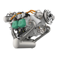
Rotax 914 UL 3 Maintenance Manual (456 pages)
912/914 Series
Brand:
Rotax
| Category:
Engine
| Size: 15.04 MB
Table of Contents
Table of Contents
3
2 List of Chapters
5
3 Index
7
4 List of the Valid Pages
11
5 Table of Amendments
19
6 General Note
21
7 Safety Notice
23
Repeating Symbols
23
8 Technical Documentation
25
Filling in the Dimension Sheets
25
List of Abbreviations
26
9 Classification of Parts for Maintenance/Repair
27
Determination of Actual Wear [%]
30
10 Maintenance
33
Trouble Shooting
33
Tightening Torques
33
Consumable Materials
34
Auxiliary Tools
37
Measuring Tools
39
Table of Contents
47
2 System Description
49
Description of Design
49
Type Description
50
3 Technical Data
57
Operating Limits
57
Operating Fluids / Capacity
57
Weights
57
Engine / Components
58
4 Treatment of Corrosion and Surface Damage
61
Propeller Shaft
61
5 Preservation and Returning to Service
63
Storage and Preservation Directives for a New Engine
63
Preservation of an Engine Which Has Been in Operation
64
Returning the Engine to Service
64
6 Maintenance
65
Engine Suspension Frame
65
1) Engine Suspension Frame Disassembly
65
2) Engine Suspension Frame Inspection
66
3) Engine Suspension Frame Assembly
66
Temperature- and Pressure Observation
68
Systems Description/Maintenance
69
2 Systems Description
73
Propeller Gearbox
73
Hydraulic Governor
75
Vacuum Pump
76
Connections for Instrumentation
76
1) Mechanical Rev Counter and Hourmeter (Optional)
76
3 Maintenance
77
Removal of the Fly Wheel Hub
77
Vacuum Pump Removal and Inspection
78
Governor Removal and Inspection
78
Ignition Housing Removal and Inspection
79
Ignition Housing Fitting
82
Sprag Clutch
83
1) Sprag Clutch Removal
84
2) Sprag Clutch Dismantling
85
3) Sprag Clutch Installation
86
Reduction Gear for Electric Starter
88
Rev Counter Drive
89
Propeller Gearbox
90
3) Removal of Roller Bearing for - Series 4
92
4) Propeller Gearbox Disassembly
96
5) Propeller Shaft Removal
98
6) Vacuum Pump Drive Removal
100
7) Propeller Governor Drive Removal
101
9) Vacuum Pump Drive Installation
106
10) Gearbox Components Inspection
107
11) Toothed Shaft Profiles Inspection
111
12) Gear Set (Gear Wheels) Inspection
112
13) Propeller Gearbox Reassembly
117
14) Disc Spring Pre-Tension Adjustment
119
15) Propeller Gearbox - Installation
121
Cylinder Head - Removal
123
Cylinder Head - Disassembly
125
1) Cylinder Head and Studs
127
2) Reworking of the Sealing Surface to the Exhaust Manifold
129
3) Valve Guides
130
4) Valve Seats
131
5) Valves
132
6) Valve Springs
135
7) Washers
137
8) Rocker Arm and Rocker Arm Shaft
138
1) Rocker Arm with Plastic Bushing
139
2) Rocker Arm with Pressed Sinter Bushing
140
3) Rocker Arm Shaft
140
Cylinder Head Reassembly
141
Cylinder and Piston - Removal
143
1) Checking Pistons
145
2) Checking the Piston Ring
147
3) Piston Pin
148
4) Cylinders Inspection
149
Hydraulic Valve Tappets
151
Pushrods
153
1) Hydraulic Valve Tappets Fitting
154
2) Pistons Fitting
154
Piston and Cylinder Assembly Fitting
154
3) Cylinders Fitting
158
4) Cylinder Head Fitting
160
Intake Manifold and Compensation Tube Assembly
163
4 Wear Limits
165
Cylinder Head
176
5 Form Sheets
185
Form Sheet for Material Testing ROTAX 912/914 Series
185
1) Inspection on Cracks
185
Systems Description/Maintenance
187
2 Systems Description
189
Fuel System (on 912 Series)
189
Fuel System (on 914 Series)
191
Fuel Filter
193
Fuel Pump (on 912 Series)
193
Fuel Pump (on 914 Series)
193
Fuel Pressure Regulator (Only on 914 Series)
194
Pressure Connecting Lines (Only on 914 Series)
196
BING Constant Depression Carburetor Type 64-3
198
Handling of Fuel
201
Connections for Instrumentation
202
1) Airbox Air Temperature Display (Only on 914 Series)
202
2) Boost Pressure Display
202
Carb Heat System and Winter Operation
202
3 Maintenance
203
BING-Constant Depression Carburetor Inspection
207
2) Float Needle Valve Leakage Test
208
3) Individual Components of the Carburetor (on the 912 Series)73-00-00
209
4) Individual Components of the Carburetor (on the 914 Series)73-00-00
210
5) Diaphragm
211
6) Jet Needle
211
7) Float Chamber, Floats
213
8) Float Brackets
214
9) Carburetor Jets
215
10) Float Needle Valve Inspection
216
11) Starting Carburetor (Choke)
217
12) Carburetor Assembly
217
13) Carburetor Synchronization
219
14) Idle Speed Adjustment
219
15) Throttle Cable and Linkage
219
General Information on the Fuel System
220
1) Fuel Pressure (on 912 Series)
221
2) Fuel Pressure (on 914 Series)
223
3) Carburetor Sockets
224
4) Fuel Lines (on 912 Series)
226
5) Fuel Lines (on 914 Series)
229
6) Fuel Pressure Regulator (Only on 914 Series)
230
7) Fuel Pump (on 912 Series)
231
8) Fuel Pump (on 914 Series)
233
9) Pressure Connecting Lines (Only on 914 Series)
235
Assembly of Carburetor Sockets, Carburetor and Fuel Lines
239
1) Carburetors and Carburetor Sockets
239
2) Fuel Lines (on 912 Series)
241
3) Fuel Lines (on 914 Series)
244
Intake Manifolds Fitting
246
Engaging the Carburetor Support
246
Connecting Fuel Lines (Tank)
247
Systems Description/Maintenance / Troubleshooting
249
2 Systems Description
251
Electric System (Alternators, Ignition)
251
1) Ignition
254
2) Allocation of Trigger Coils and Ignition Circuits
256
3) Firing Order
257
Connections for Instrumentation
257
1) Electronic Rev Counter
257
3 Maintenance / Troubleshooting
259
Treatment of Corrosion and Surface Damage
259
Electric System
259
Checking the Ignition Unit, Trouble Shooting
259
Spark Plugs
260
Spark Plug Connectors and Ignition Cables
260
Electronic Module, Trigger Coil Kit
262
Charging Coil
263
Generator Coils
264
Dual Ignition Coil
265
Cut-In Speed of Ignition
266
Ignition Timing Control
267
Ignition Circuits Inspection (Ignition Check)
269
Measurement Values for the Ignition Unit
270
Wiring Diagrams
272
1) Engine Internal (on the 912 Series)
272
Engine Internal (on the 914 Series)
278
Engine External (on the 914 Series)
282
Ignition Electric Set Removal
283
Ignition Electric Set Dismantling
285
Dual Ignition Coils Replacement
285
Ignition Electric Set Reassembly
289
Ignition Electric Set Refitting
291
Trigger Coil Kit Replacement
294
Stator Removal and Refitting
296
Fly Wheel Hub
297
Interference Suppression Box (Only on the 912 Series)
300
1) Interference Suppression Box Dismantling
300
2) Interference Suppression Box Wiring Diagram
301
3) Interference Suppression Box Assembly
302
4) Interference Suppression Box Fitting
302
Rev Counter and Ignition Trigger Coils
303
External Alternator (Optional on 912/914 Series)
305
1) Vbelt Pulley Assembly
305
2) Alternator Assembly
305
3) V-Belt Tension
307
4 Wear Limits
309
5 Form Sheets
311
Table of Contents
313
2 Systems Description
315
Cooling System
315
Connections for Instrumentation
316
3 Maintenance
317
Water Pump Removal and Inspection
318
Water Pump Housing - Dismantling and Inspection
319
Fly Wheel Hub Removal
321
Ignition Housing Removal
321
Water Pump Shaft - Removal
321
Rotary Seal - Removal
322
Rotary Seal - Installation
322
Axial Position of the Water Pump Shaft
324
Ignition Housing Assembly
325
Water Pump Housing - Reassembly
325
Coolant Hoses Fitting
326
Spring Band Hose Clamps
326
Radiator (Optional 912/ 914 Series)
326
Cooling Air Duct (Optional 912/ 914 Series)
326
Expansion Tank
327
Overflow Bottle
327
Temperature Measurement System
327
1) Cylinder Head Temperature Sensor
327
4 Wear Limits
331
Water Pump
331
Systems Description/Maintenance
333
2 Systems Description
335
Turbocharger Control (Only on 914 Series)
335
1) Target Pressure Reduction at Overspeeding
340
2) Target Pressure Reduction
340
2) Target Pressure Reduction at Excessive Airbox
341
3) Target Pressure Reduction by Limiting the Compressor
342
Pressure Ratio
342
3) Lamp Output Connections on the TCU
343
4) Three-Way Solenoid Valve
344
5) PC Interface
344
3 Maintenance
345
Control System of the Turbocharger (Only on 914 Series)
345
1) Checking the Turbocharger Control Unit (TCU) by Means
345
1) Functions of the Communication Program
345
2) Required Items
345
3) Scope of the Communication Program
347
4) Application of the Communication Program
349
6) Checking the Throttle Valve Position
361
7) Recalibration of the Throttle Position
363
2) Static Check of the Turbocharger Control
364
1) Turbo Control Unit (TCU)
364
2) Caution Lamps
366
3) Wiring Harness
367
4) Throttle Potentiometer
369
5) Resistance Thermometer
374
6) Pressure Sensors
376
7) Servo Motor
382
8) Circuit Breaker for Servo Motor
384
9) Three-Way Solenoid Valve
385
Wiring Diagrams
386
Engine External (on the 914 Series)
386
4 Form Sheets
387
Systems Description/Maintenance
389
2 Systems Description
391
Exhaust System (on the 912 Series)
391
Exhaust System (on the 914 Series)
391
Turbocharger (Only on the 914 Series)
391
1) Exhaust Turbocharger
391
Connections for Instrumentation
393
1) Exhaust Gas Temperature Display (Optional)
393
3 Maintenance
395
Disassembly of the Complete Exhaust System
395
Disassembly of the Complete Exhaust System Incl. Turbocharger
395
Inspection of the Exhaust System and Turbocharger Components
399
(Only on the 914 Series)
399
1) Exhaust Bend and Exhaust Manifold
399
2) Muffler
399
Turbocharger
400
Assembly of the Complete Exhaust System (on the 912 Series)
403
Assembly of the Complete Exhaust System Incl. Turbocharger
403
Owden Cable, Rope Sheave and Spring for Wastegate Control
407
2) Checking of the Components
408
3) Assembly and Adjustment
408
Table of Contents
411
2 Systems Description
413
Lubrication System
413
Main Oil Pump (Engine Lubrication Circuit)
415
Suction Pump (Turbocharger Oil Circuit, Only on 914 Series)
418
Magnetic Plug
420
Drain Plug
420
Connections for Instrumentation
420
1) Oil Pressure Indication
420
2) Oil Temperature Indication
420
3 Maintenance
421
Oil Pump
421
1) Oil Pump Removal (Main and Suction Pump)
421
2) Oil Pump Disassembly
424
4) Oil Pump Assembly (on 912 Series)
428
Pressure Check Valve (Only on 914 Series)
430
Oil Sump (Only on 914 Series)
431
Oil Tank
432
Oil Lines (Steel Lines)
433
Oil Lines
435
Oil Cooler
435
Purging of Lubrication System
436
Temperature- and Pressure Observation
436
1) Oil Temperature Sensor
436
2) Oil Pressure Sensor
437
4 Wear Limits
439
Systems Description
443
Electric Starter
443
Maintenance
445
Electric Starter Dismantling
445
1) Standard Starter
447
Electric Starter - Inspection of Individual Parts
449
Electric Starter - Reassembly
451
1) Standard Starter
452
2) HD Starter
452
Electric Starter - Installation
452
Advertisement
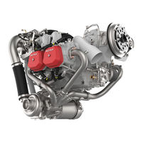
Rotax 914 UL 3 Installation Manual (142 pages)
914 series
Brand:
Rotax
| Category:
Engine
| Size: 4.84 MB
Table of Contents
1 Table of Contents
3
2 Index
7
3 Preface
9
Remarks
9
Engine Serial Number
9
ROTAX Authorized Distributors for Aircraft Engines
9
4 Safety
11
Repeating Symbols
11
Safety Information
11
Instruction
13
Technical Documentation
14
5 List of the Effective
17
6 Table of Amendments
19
7 Description of Design
21
Designation of Type
21
Standard Engine Design
21
Auxiliary Equipment
22
Engine Components, Engine Views, Definition of Main Axes
24
8 Technical Data
27
Operating Limits
27
Installation Dimensions (All Dimensions in MM)
28
Weights
28
Centre of Gravity of Engine and Standard Equipment
29
Moments of Inertia
29
9 Preparations for Engine Installation
31
Transport
31
State of Delivery
31
Engine Preservation
31
Protective Covering
32
10 Engine Suspension and Position
33
Definition of Attachment Points
34
Permissible Fitting Positions
35
General Directives for Engine Suspension
38
11 Exhaust System
39
Operating Limits
40
General Notes Concerning the Exhaust System
41
12 Cooling System
43
Description of the System
43
Operating Limits
44
Coolant Types
45
Check Cooling System - Efficiency of the Cooling System
46
1)Measurement of Cylinder Head Temperature and Coolant Exit Temperature
46
Determination of Operating Limits, Coolant and Necessary Modification on Radiator Installation
48
Requirements on the Cooling System
50
Size and Position of Connections
51
Water Inlet Bend
53
Requirements, Feasible Location and Fitting Position Concerning Radiator/ Expansion Tank/Overflow Bottle
54
Overflow Bottle
55
General Directives for the Cooling System
57
Coolant Capacity
59
Cooling Air Ducting
59
1)General Directives for Ducting of the Cooling Air
60
Data for Optional Components of Cooling System
61
13 Lubrication System
63
Description of the System
63
Limits of Operation
64
Checking of the Lubrication System
65
1) Measuring of the Vacuum
65
2) Measuring of the Pressure in the Crankcase
66
Requirements on the Oil- and Venting Lines
67
Connecting Dimensions and Location of Connections
68
1) Oil Circuit (Engine)
68
2) Oil Circuit (Turbo Charger)
71
3) Oil Tank
72
Effectivity: 914 Series Page
73
Feasible Position and Location of the Oil Tank
74
Feasible Position and Location of the Oil Cooler
75
General Notes on Oil Cooler
75
Filling Capacity
75
Venting (Purging or Priming) of Lubrication System
76
1)Venting (Purging or Priming) of Turbocharger Lubrication System
77
Inspection for Correct Venting (Priming) of Hydraulic Valve Tappets
78
Replacement of Components
79
Data for Optional Components of Oil System
80
14 Fuel System
83
Description of System
83
Operating Limits
85
Requirements of the Fuel System
86
Connecting Dimensions, Location of Joints and Directives for Installation
87
1) Electric Fuel Pump
87
2) Check Valve
89
3) Fuel Pressure Control
89
Notes on Checking of Fuel Pressure
90
15 Carburetor
91
Requirements on the Carburetor
91
1) Drainage Pipelines to Airbox and Trip Tray
92
Connections for Bowden-Cable Actuation and Limit Load
93
Requirements on Cable Actuation
94
Requirements on the Throttle Lever
95
Location and Determination of the Throttle Position for Max. Continuous Power
96
16 Air Intake System
97
Operating Limits
97
Requirements on the Air Intake System
98
1) Requirements on the Intake Air Ducting
98
2) Requirements on the Intercooler
99
3) Airfilter
100
4) Airbox
100
Additional Notes Concerning Air Intake System
102
17 Pressure Sensors
103
Static Pressure Sensor
104
18 Servo Motor/Servo Cable
105
Servo Motor
105
Servo Cable
106
19 Electric System
107
Requirements on Circuit Wiring
108
1) Electromagnetic Compatibility (EMC)
108
Wiring Diagram
109
Description of the Turbo Control Unit (TCU)
111
Technical Data and Connection of the Electric Components
111
1) Integrated Generator
111
2) Rectifier-Regulator
112
3) Electronic Modules
114
4) Ignition Switches (On-Off Switch)
114
5) Electric Starter
116
6) Starter Relay
117
7) Electric Fuel Pumps
118
8) Turbo Control Unit (TCU)
119
9) Isolating Switch for Servo Motor
121
10)Boost Lamp
122
11)Caution Lamp
122
12)External Alternator (Optional Extra)
123
13)Connection of the Electric Rev-Counter (Tachometer)
125
14) Battery
126
15) Relay
126
Internal Consumer of Electric Power
126
20 Propeller Drive
127
Technical Data
127
21 Vacuum Pump
129
Technical Data
129
22 Hydraulic Governor for Constant Speed Propeller
131
Technical Data
131
23 Connections for Instrumentation
133
Sensor for Cylinder Head Temperature
133
Sensor for Oil Temperature
134
Oil Pressure Sensor
135
Mechanical Rev-Counter (Tach Drive)
136
Monitoring of the Intake Manifold Pressure
137
Air Temperature in the Airbox (Optional)
138
24 Preparations for Trial Run of Engine
139
Rotax 914 UL 3 Maintenance Manual (124 pages)
Brand:
Rotax
| Category:
Engine
| Size: 2.18 MB
Table of Contents
Section 00-00 Introduction Section 00 Introduction
3
Table of Contents
3
List of Chapters
5
Index
7
Introduction
9
Remarks
9
Engine Serial Number
9
Conversion Table and Abbreviations
11
Safety Notice
13
Symbols Used
14
Maintenance Concept
15
Technical Documentation
16
1) Use for Intended Purpose
17
2) Instruction
18
List of Effective Pages
19
Table of Amendments
21
Section 05-00 Time Limits / Maintenance Checks
23
General Note
27
Maintenance
27
Authorized Personnel
28
Procedure Notes
29
Trouble Shooting
30
Consumable Materials
31
1) Securing Elements
34
Acceptable Methods, Techniques and Practice
34
Lock Washer
34
Nut Securing
34
General Note
35
Time Limits
35
Time Limits for Engine Operation
37
Annual Inspection
39
Time Limit for Rubber Parts
39
Time Limit for the Coolant
39
Maintenance Schedule Procedures (Maintenance Check List)
42
Check List / Maintenance Schedule
43
Identification
43
1) Engine Cleaning
45
2) Visual Inspection of the Engine
45
Maintenance Schedule
45
3) Checking the Engine Suspension
46
4) Engine External Parts
47
6) Checking the Propeller Gearbox
47
7) Oil Level Check, Magnetic Plug
47
8) Oil Change
48
9) Flushing the Cooling System
48
10) Checking the Air Filter
49
11) Inspecting Carburetor Sockets and Drip Tray
49
12) Checking the Carburetors
49
13) Checking the V-Belt Tension
50
14) Spark Plugs
50
15) Spark Plug Connectors
50
17) Checking the Compression
50
18) Engine Test Run
51
19) General Note
51
General Note
53
Unscheduled Maintenance Checks
53
1) Propeller Gearbox with Integrated Overload Clutch
55
Checking the Propeller Gearbox/Engine
55
Special Checks
55
2) Propeller Gearbox Without Integrated Overload Clutch
56
Checking of the Overload Clutch
57
Examination after Engine Failure
59
Edition 1 / Rev
60
Effectivity 914 Series
60
Inspection in Extreme Climatic Conditions
60
Returning Engine to Service after Submerging in Water
60
Exceeding of Max. Admissible Engine RPM
61
1) Max. Temperature Exceeded
62
2) Excess Temperature of over 180 °C (356 °F)
62
Exceeding of Max. Cylinder Head Temperature
62
1) Excess Temperature over 130 °C (266 °F)/Max. 15 Min
63
2) Excess Temperature over 160 °C (320 °F)
63
Exceeding the Max. Permissible Oil Temperature
63
1) Oil Pressure below Minimum Oil Pressure on the Ground . 05-50-00
64
2) Oil Pressure below Minimum Permissible Oil Pressure
64
3) Oil Pressure below Minimum Permissible Value
64
Oil Pressure below Minimum Value
64
Oil Specification Not Respected
66
Spark Plug Not in Accordance with Specification
67
Engine Runs Sluggishly
68
(Vibration of Turbo Control Unit)
69
Periodic Rise and Fall in Boost Pressure and Speed
69
Sudden Drop in Boost Pressure and Speed
69
Sudden Increase in Boost Pressure and Speed
69
Red Boost Lamp of the Boost Pressure Control Lights
70
Red Boost Lamp of the Boost Pressure Control Is Flashing
71
Failure of the Voltage Supply for the Turbo Control Unit (TCU)
72
Orange Caution Lamp of the Boost Pressure Control Is Flashing
72
Reporting
73
Section 12-00 Maintenance of the Systems Section 12 Maintenance of the Systems
75
General Note
77
Engine Cleaning
78
Visual Inspection of the Engine and Accessories
78
Leakage Check
80
Checking the Engine Suspension
81
Checking the Air Filter
82
Checking the Compression
84
Checking the V-Belt Tension
86
Locking the Crankshaft
87
Checking the Wastegate Flap
88
Inspection of the Fuel Filter in the Airframe
89
Test Run of Engine
90
Checking the Cooling System
93
Cooling System
93
Replacing the Coolant
94
Flushing the Cooling System
95
Expansion Tank, Radiator Cap
96
Overflow Bottle
97
1) Checking the Synchronization at Idle Speed
99
2) Mechanical Synchronization
99
Carburetor Synchronization
99
Fuel System
99
3) Pneumatic Synchronization
101
Idle Speed Adjustment
104
Checking the Carburetor Actuation
105
Lubrication System
107
Oil Level Check
107
Oil Change
108
1) Cleaning the Oil Tank
109
2) Venting the Oil System
110
Oil Filter Replacement and Inspection of the Filter Insert
112
Inspecting the Magnetic Plug
115
Accessories (Including Radiator, Oil Hoses, Clamps Etc.)
116
Flushing the Oil Circuit
116
Check of Wiring
117
Electric System
117
Inspection and Replacement of Spark Plugs
118
Checking the Friction Torque in Free Rotation
121
Propeller Gearbox
121
Checking the Propeller Gearbox
122
Advertisement
Advertisement
Related Products
Rotax 914 series
Rotax 914 F
Rotax 912 ULS 3
Rotax 912-UL
Rotax 912 i series
Rotax 912 A
Rotax 912 S
Rotax 912 F
Rotax 912 iS Sport
Rotax 915 iS 3 A
Rotax Categories
Engine
Lubrication systems
Offroad Vehicle
Boat
Outboard Motor
More Rotax Manuals
Login
Sign In
OR
Sign in with Facebook
Sign in with Google
Upload manual
Upload from disk
Upload from URL