Rotax 914 F Manuals
Manuals and User Guides for Rotax 914 F. We have 2 Rotax 914 F manuals available for free PDF download: Maintenance Manual, Installation Manual

Rotax 914 F Maintenance Manual (274 pages)
Table of Contents
-
2 Index
9 -
-
Remarks12
-
-
4 Safety
12 -
-
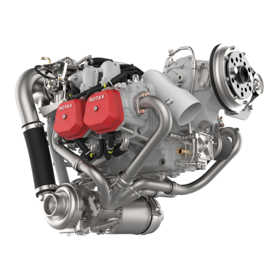
Engine Views24
-
-
Fuel System32
-
-
-
-
Consumables76
-
1) Motor Oil77
-
8) Silastic77
-
-
-
-
24)Overhaul111
-
Special Checks113
-
-
Fuel System124
-
-
1) General124
-
4) Diaphragm127
-
8) Jets128
-
-
6) Fuel Pressure133
-
8) Fuel Tubes135
-
10) Fuel Pump136
-
-
1) Oil Pump142
-
5) Drain Screw147
-
6) Oil Tank148
-
8) Oil Tubes150
-
9) Oil Cooler150
-
-
Cooling System152
-
3) Magneto Hub154
-
13) Radiator162
-
15) Hose Clamps162
-
Ignition System164
-
4) Charging Coil166
-
-
1) Disassembly194
-
-
6) Servo Motor220
-
-
-
Electric Starter228
-
Sprag Clutch230
-
-
7) Vacuum Pump238
-
-
2) Valve Guides249
-
3) Valve Seats249
-
4) Valves249
-
5) Valve Springs250
-
6) Rocker Arms250
-
Push Rods255
-
-
16 Form Sheets
266 -
18 Reporting
271
Advertisement

Advertisement