Sign In
Upload
Manuals
Brands
Rotax Manuals
Engine
912 ULS 3
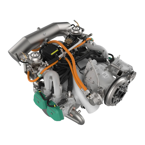
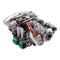
Rotax 912 ULS 3 Manuals
Manuals and User Guides for Rotax 912 ULS 3. We have
7
Rotax 912 ULS 3 manuals available for free PDF download: Maintenance Manual, Installation Manual, Operator's Manual
Rotax 912 ULS 3 Maintenance Manual (456 pages)
912/914 Series
Brand:
Rotax
| Category:
Engine
| Size: 15.04 MB
Table of Contents
Table of Contents
3
2 List of Chapters
5
3 Index
7
4 List of the Valid Pages
11
5 Table of Amendments
19
6 General Note
21
7 Safety Notice
23
Repeating Symbols
23
8 Technical Documentation
25
Filling in the Dimension Sheets
25
List of Abbreviations
26
9 Classification of Parts for Maintenance/Repair
27
Determination of Actual Wear [%]
30
10 Maintenance
33
Trouble Shooting
33
Tightening Torques
33
Consumable Materials
34
Auxiliary Tools
37
Measuring Tools
39
Table of Contents
47
2 System Description
49
Description of Design
49
Type Description
50
3 Technical Data
57
Operating Limits
57
Operating Fluids / Capacity
57
Weights
57
Engine / Components
58
4 Treatment of Corrosion and Surface Damage
61
Propeller Shaft
61
5 Preservation and Returning to Service
63
Storage and Preservation Directives for a New Engine
63
Preservation of an Engine Which Has Been in Operation
64
Returning the Engine to Service
64
6 Maintenance
65
Engine Suspension Frame
65
1) Engine Suspension Frame Disassembly
65
2) Engine Suspension Frame Inspection
66
3) Engine Suspension Frame Assembly
66
Temperature- and Pressure Observation
68
Systems Description/Maintenance
69
2 Systems Description
73
Propeller Gearbox
73
Hydraulic Governor
75
Vacuum Pump
76
Connections for Instrumentation
76
1) Mechanical Rev Counter and Hourmeter (Optional)
76
3 Maintenance
77
Removal of the Fly Wheel Hub
77
Vacuum Pump Removal and Inspection
78
Governor Removal and Inspection
78
Ignition Housing Removal and Inspection
79
Ignition Housing Fitting
82
Sprag Clutch
83
1) Sprag Clutch Removal
84
2) Sprag Clutch Dismantling
85
3) Sprag Clutch Installation
86
Reduction Gear for Electric Starter
88
Rev Counter Drive
89
Propeller Gearbox
90
3) Removal of Roller Bearing for - Series 4
92
4) Propeller Gearbox Disassembly
96
5) Propeller Shaft Removal
98
6) Vacuum Pump Drive Removal
100
7) Propeller Governor Drive Removal
101
9) Vacuum Pump Drive Installation
106
10) Gearbox Components Inspection
107
11) Toothed Shaft Profiles Inspection
111
12) Gear Set (Gear Wheels) Inspection
112
13) Propeller Gearbox Reassembly
117
14) Disc Spring Pre-Tension Adjustment
119
15) Propeller Gearbox - Installation
121
Cylinder Head - Removal
123
Cylinder Head - Disassembly
125
1) Cylinder Head and Studs
127
2) Reworking of the Sealing Surface to the Exhaust Manifold
129
3) Valve Guides
130
4) Valve Seats
131
5) Valves
132
6) Valve Springs
135
7) Washers
137
8) Rocker Arm and Rocker Arm Shaft
138
1) Rocker Arm with Plastic Bushing
139
2) Rocker Arm with Pressed Sinter Bushing
140
3) Rocker Arm Shaft
140
Cylinder Head Reassembly
141
Cylinder and Piston - Removal
143
1) Checking Pistons
145
2) Checking the Piston Ring
147
3) Piston Pin
148
4) Cylinders Inspection
149
Hydraulic Valve Tappets
151
Pushrods
153
1) Hydraulic Valve Tappets Fitting
154
2) Pistons Fitting
154
Piston and Cylinder Assembly Fitting
154
3) Cylinders Fitting
158
4) Cylinder Head Fitting
160
Intake Manifold and Compensation Tube Assembly
163
4 Wear Limits
165
Cylinder Head
176
5 Form Sheets
185
Form Sheet for Material Testing ROTAX 912/914 Series
185
1) Inspection on Cracks
185
Systems Description/Maintenance
187
2 Systems Description
189
Fuel System (on 912 Series)
189
Fuel System (on 914 Series)
191
Fuel Filter
193
Fuel Pump (on 912 Series)
193
Fuel Pump (on 914 Series)
193
Fuel Pressure Regulator (Only on 914 Series)
194
Pressure Connecting Lines (Only on 914 Series)
196
BING Constant Depression Carburetor Type 64-3
198
Handling of Fuel
201
Connections for Instrumentation
202
1) Airbox Air Temperature Display (Only on 914 Series)
202
2) Boost Pressure Display
202
Carb Heat System and Winter Operation
202
3 Maintenance
203
BING-Constant Depression Carburetor Inspection
207
2) Float Needle Valve Leakage Test
208
3) Individual Components of the Carburetor (on the 912 Series)73-00-00
209
4) Individual Components of the Carburetor (on the 914 Series)73-00-00
210
5) Diaphragm
211
6) Jet Needle
211
7) Float Chamber, Floats
213
8) Float Brackets
214
9) Carburetor Jets
215
10) Float Needle Valve Inspection
216
11) Starting Carburetor (Choke)
217
12) Carburetor Assembly
217
13) Carburetor Synchronization
219
14) Idle Speed Adjustment
219
15) Throttle Cable and Linkage
219
General Information on the Fuel System
220
1) Fuel Pressure (on 912 Series)
221
2) Fuel Pressure (on 914 Series)
223
3) Carburetor Sockets
224
4) Fuel Lines (on 912 Series)
226
5) Fuel Lines (on 914 Series)
229
6) Fuel Pressure Regulator (Only on 914 Series)
230
7) Fuel Pump (on 912 Series)
231
8) Fuel Pump (on 914 Series)
233
9) Pressure Connecting Lines (Only on 914 Series)
235
Assembly of Carburetor Sockets, Carburetor and Fuel Lines
239
1) Carburetors and Carburetor Sockets
239
2) Fuel Lines (on 912 Series)
241
3) Fuel Lines (on 914 Series)
244
Intake Manifolds Fitting
246
Engaging the Carburetor Support
246
Connecting Fuel Lines (Tank)
247
Systems Description/Maintenance / Troubleshooting
249
2 Systems Description
251
Electric System (Alternators, Ignition)
251
1) Ignition
254
2) Allocation of Trigger Coils and Ignition Circuits
256
3) Firing Order
257
Connections for Instrumentation
257
1) Electronic Rev Counter
257
3 Maintenance / Troubleshooting
259
Treatment of Corrosion and Surface Damage
259
Electric System
259
Checking the Ignition Unit, Trouble Shooting
259
Spark Plugs
260
Spark Plug Connectors and Ignition Cables
260
Electronic Module, Trigger Coil Kit
262
Charging Coil
263
Generator Coils
264
Dual Ignition Coil
265
Cut-In Speed of Ignition
266
Ignition Timing Control
267
Ignition Circuits Inspection (Ignition Check)
269
Measurement Values for the Ignition Unit
270
Wiring Diagrams
272
1) Engine Internal (on the 912 Series)
272
Engine Internal (on the 914 Series)
278
Engine External (on the 914 Series)
282
Ignition Electric Set Removal
283
Ignition Electric Set Dismantling
285
Dual Ignition Coils Replacement
285
Ignition Electric Set Reassembly
289
Ignition Electric Set Refitting
291
Trigger Coil Kit Replacement
294
Stator Removal and Refitting
296
Fly Wheel Hub
297
Interference Suppression Box (Only on the 912 Series)
300
1) Interference Suppression Box Dismantling
300
2) Interference Suppression Box Wiring Diagram
301
3) Interference Suppression Box Assembly
302
4) Interference Suppression Box Fitting
302
Rev Counter and Ignition Trigger Coils
303
External Alternator (Optional on 912/914 Series)
305
1) Vbelt Pulley Assembly
305
2) Alternator Assembly
305
3) V-Belt Tension
307
4 Wear Limits
309
5 Form Sheets
311
Table of Contents
313
2 Systems Description
315
Cooling System
315
Connections for Instrumentation
316
3 Maintenance
317
Water Pump Removal and Inspection
318
Water Pump Housing - Dismantling and Inspection
319
Fly Wheel Hub Removal
321
Ignition Housing Removal
321
Water Pump Shaft - Removal
321
Rotary Seal - Removal
322
Rotary Seal - Installation
322
Axial Position of the Water Pump Shaft
324
Ignition Housing Assembly
325
Water Pump Housing - Reassembly
325
Coolant Hoses Fitting
326
Spring Band Hose Clamps
326
Radiator (Optional 912/ 914 Series)
326
Cooling Air Duct (Optional 912/ 914 Series)
326
Expansion Tank
327
Overflow Bottle
327
Temperature Measurement System
327
1) Cylinder Head Temperature Sensor
327
4 Wear Limits
331
Water Pump
331
Systems Description/Maintenance
333
2 Systems Description
335
Turbocharger Control (Only on 914 Series)
335
1) Target Pressure Reduction at Overspeeding
340
2) Target Pressure Reduction
340
2) Target Pressure Reduction at Excessive Airbox
341
3) Target Pressure Reduction by Limiting the Compressor
342
Pressure Ratio
342
3) Lamp Output Connections on the TCU
343
4) Three-Way Solenoid Valve
344
5) PC Interface
344
3 Maintenance
345
Control System of the Turbocharger (Only on 914 Series)
345
1) Checking the Turbocharger Control Unit (TCU) by Means
345
1) Functions of the Communication Program
345
2) Required Items
345
3) Scope of the Communication Program
347
4) Application of the Communication Program
349
6) Checking the Throttle Valve Position
361
7) Recalibration of the Throttle Position
363
2) Static Check of the Turbocharger Control
364
1) Turbo Control Unit (TCU)
364
2) Caution Lamps
366
3) Wiring Harness
367
4) Throttle Potentiometer
369
5) Resistance Thermometer
374
6) Pressure Sensors
376
7) Servo Motor
382
8) Circuit Breaker for Servo Motor
384
9) Three-Way Solenoid Valve
385
Wiring Diagrams
386
Engine External (on the 914 Series)
386
4 Form Sheets
387
Systems Description/Maintenance
389
2 Systems Description
391
Exhaust System (on the 912 Series)
391
Exhaust System (on the 914 Series)
391
Turbocharger (Only on the 914 Series)
391
1) Exhaust Turbocharger
391
Connections for Instrumentation
393
1) Exhaust Gas Temperature Display (Optional)
393
3 Maintenance
395
Disassembly of the Complete Exhaust System
395
Disassembly of the Complete Exhaust System Incl. Turbocharger
395
Inspection of the Exhaust System and Turbocharger Components
399
(Only on the 914 Series)
399
1) Exhaust Bend and Exhaust Manifold
399
2) Muffler
399
Turbocharger
400
Assembly of the Complete Exhaust System (on the 912 Series)
403
Assembly of the Complete Exhaust System Incl. Turbocharger
403
Owden Cable, Rope Sheave and Spring for Wastegate Control
407
2) Checking of the Components
408
3) Assembly and Adjustment
408
Advertisement
Rotax 912 ULS 3 Maintenance Manual (126 pages)
Brand:
Rotax
| Category:
Engine
| Size: 7.22 MB
Table of Contents
1 Table of Contents Table of Contents
2
Table of Contents
2
2 Index
6
3 List of the Current
8
4 Table of Amendments
10
5 Introduction
13
6 Safety
13
Repeating Symbols
13
7 Technical Documentation
13
8 General
13
9 Auxiliary Equipment
13
10 Description of Design
13
11 Maintenance
15
General Note
15
Version
15
Procedure Notes
15
Auxiliary Tools
16
Measuring Tools
17
Special Tools and Devices
18
Consumable Materials
24
Motor Oil
26
Lithium Grease
26
Multi-Purpose Grease LZ
26
4) Corrosion Inhibiting Oil Mobil®Arma 524
26
Silastic 743 Rtv
26
Loctite® Antiseize 15378
26
LOCTITE® "574 Orange
26
8) LOCTITE® "380 Black
27
9) LOCTITE® "648 Green
27
10) LOCTITE® "221 Violet
27
11) LOCTITE® "243 Blue
27
12) LOCTITE® "603 Green
27
13) MICRONORM Shot Blasting Abrasive
27
14) Lapping Fleece SR 4600 a - very Fine Grading
28
15) Cleaning Agents
28
16) Valve Lapping Paste
28
17) MOLYKOTE® 44 Medium
28
18) Grease MOLYKOTE® GN
28
19) K&N® Filteroil 99 - 1131
28
Securing Elements
29
Safety Wiring
29
2) Nut Securing
30
Tightening Torques
31
Treatment of Corrosion and Surface Damages
32
Engine Preservation and Engine Back to Operation
32
1) Preservation of a New Engine
33
2) Engine Back to Operation
33
12 Periodic Maintenance
34
13 Maintenance of the Systems
35
Fuel System
35
1) Removal of Carburetors and Carburetor Flange
35
BING Constant Depression Carburetor: Check and Maintenance
36
1) Leakage Test of Float Needle Valve
36
2) Diaphragm
37
3) Jet Needle
37
4) Jets
38
5) Float Chamber
38
6) Float Suspension
39
7) Check of Float Needle Valve
39
8) Starting Carburetor (Choke)
40
Check of the Fuel System
41
1) General Notes on Fuels
41
2) Fuel Pressure
42
Carburetor Flange
44
Fuel Pump
45
6) Fuel Tubes
46
7) Carburetor Flange, Carburetor
47
Lubricating System
48
1) Oil Pump Removal
48
2) Oil Pump Checking
48
3) Oil Pump Reassembly
49
Magnetic Plug
50
Drain Screw
50
Cooling System
51
1) Water Pump Removal
51
2) Water Pump Housing Disassembly and Inspection
51
Magneto Hub
52
Ignition Housing Disassembly and Inspect
52
5) Water Pump Shaft Disassembly
55
6) Rotary Seal Disassembly
55
Rotary Seal Reassembly
56
8) Crosssection of Water Pump
57
Ignition Housing Reassembly
58
10) Water Pump Housing Reassembly
59
11) Hose Clamps
60
12) Cooling Air Baffle
60
Ignition System
61
1) Checking of Ignition Unit, Trouble Shooting
61
2) Spark Plugs, Ignition Cables, Spark Plug Connectors, Cables
61
Electronic Module, Trigger Set
62
Charging Coil
63
Double Ignition Coil
63
Generator Coil
64
Resistance Values of the Ignition Unit
64
Wiring Diagrams
65
1) Wiring Diagram for Ignition System("Single Plug")
65
2) Wiring Diagram for Ignition System ("Central Plug")
66
9) Ignition Electric Set Disassembly
67
10) Ignition Electric Set Disassembly
68
Double Ignition Coil Renewal
68
11) Ignition Electric Set Reassembly
70
12) Ignition Electric Set Installation
71
13) Removal of Trigger Coil Set
72
14) Stator Removal and Re-Fitting
73
15) Magneto Hub
74
16) Interference Suppression Box
74
1) Disassembly of Interference Suppression Box
74
2) Wiring Diagram for Interference Suppression Box
75
3) Re-Assembly of Interference Suppression Box
76
4) Installation of Interference Suppression Box
76
Temperature- and Pressure Measuring System
77
1) Cylinder Head Temperature Sensor
77
Oil Temperature Sensor
78
Oil Pressure Sensor
78
14 Maintenance of Components
80
Electric Starter
80
1) Electric Starter Disassembly
80
2) Electric Starter Single Parts Check
81
Electric Starter Reassembly
82
4) Electric Starter Mounting
82
Sprag Clutch
82
1) Sprag Clutch Removal
83
2) Sprag Clutch Disassembly
84
3) Sprag Clutch Reassembly
84
4) Reduction Gear for Electric Starter
85
5) Ignition Housing Fitting
85
Rev. Counter Drive
86
Propeller Gearbox
86
Roller Bearing Removal for Configuration 1 and 2 Only
88
Roller Bearing Removal for Configuration 3 Only
89
Roller Bearing Removal for Configuration 4 Only
89
Vacuum Pump Disassembly
90
Vacuum Pump Drive Disassembly
90
6) Drive for Vacuum Pump and Hydraulic Governor Reassembly
91
7) Vacuum Pump
91
Hydraulic Governor Disassembly
92
9) Drive for Hydraulic Governor Reassembly
93
10) Propeller Gearbox Disassembly
94
11) Propeller Shaft Disassembly
96
12) Gearbox Components Check
97
13) Propeller Gearbox Refitting
99
14) Disk Spring Pre-Tension Adjust
100
15) Propeller Gearbox Installation
101
Cylinder Head Removal
103
Cylinder Head Disassembly
104
2) Valve Guides
105
3) Valve Seats
105
Valves
106
Valve Springs
106
6) Rocker Arm
107
7) Cylinder Head Hardness Test
107
8) Cylinder Heads Reassembly
108
Cylinder and Piston Disassembly
109
Piston Check
110
2) Piston Rings Check
111
3) Dimensions of Pistons and Piston Rings
111
Piston Pin
112
Cylinder Check
112
Hydraulic Valve Tappets
113
Push Rods
113
Displacement Parts Reassembly
114
Hydraulic Valve Tappets
114
2) Piston Fitting
114
3) Fitting of Cylinder
116
4) Fitting of Cylinder Head
116
Fitting of Coolant Hoses
118
Fitting of Intake Manifolds
118
Fitting of an Extra Carburetor Support
118
Connecting of the Fuel Lines
119
Rotax 912 ULS 3 Maintenance Manual (170 pages)
Brand:
Rotax
| Category:
Engine
| Size: 3.75 MB
Table of Contents
Chapter: 00-00-00 General Note
9
Table of Contents
9
General Note
11
Abbreviations and Terms Used in this Manual
13
Conversion Table
15
Safety Notice
18
Instruction
20
Maintenance Concept
21
Technical Documentation
22
Use for Intended Purpose
24
Chapter: 05-00-00 Maintenance
27
General Note
29
Maintenance
29
Authorized Personnel
30
Procedure Notes
31
Trouble Shooting
32
Consumable Materials
33
Chapter: 05-10-00 Time Limits
37
Definition of Terms
39
Life Cycle
39
Operating Hours
39
Time Limits
39
General Overhaul (TBO)
40
Time Limit
41
Annual Inspection
44
Time Limit for Rubber Parts
44
Time Limit for the Coolant
44
Chapter: 05-50-00 Unscheduled Maintenance Checks
63
Engine Check after Propeller Strike Incidents
65
Propeller Gearbox with Integrated Overload
65
Propeller Gearbox Without Integrated Overload
66
Checking of the Overload Clutch
67
Examination after Engine Failure
69
Inspection in Extreme Climatic Conditions
71
Returning Engine to Service after Submerging
71
Exceeding of Max. Admissible Engine RPM
72
Exceeding of Max. Cylinder Head Temperature
73
Exceeding the Max. Permissible Oil Tempera
75
Oil Pressure below Minimum Value
77
Oil Specification Not Respected
79
Spark Plug Not in Accordance with Specification
81
Hard to Turn over
82
Reporting
83
Chapter: 12-10-00 Replenishing Operating Fluids
89
Fluid Capacities
93
General Note
93
Coolant Check/Replenish
95
Cooling System
95
Lubrication System
97
Oil Level Check/Replenish
97
Effectivity: 912 Series 12-20-00
99
Engine Cleaning
101
Checking the Air Filter
103
Cleaning the Dry Air Filter
103
Replacing the Dry Air Filter
105
Checking the Engine Suspension
107
Visual Inspection
107
Corrosion
108
Leakage Check
109
Checking the Compression
111
Checking the V-Belt Tension
115
Locking the Crankshaft
117
Test Run of Engine
119
Checking the Cool System
121
Cooling System
121
Replacing the Coolant
122
Flushing the Cooling System
124
Expansion Tank, Radiator Cap
125
Accessories
127
Overflow Bottle
127
Carburetor Synchronization
129
Fuel System
129
Mechanical Synchronization
130
Pneumatic Synchronization
132
Idle Speed Check
136
Operating Range Check
137
Checking of the Float Chamber
139
Idle Speed Adjustment
141
Checking the Carburetor Actuation
142
Oil Change
147
Oil Filter Replacement
148
Install Oil Filter
149
Inspection of the Oil Filter Insert
150
Cleaning the Oil Tank
152
Purging the Oil System
154
Inspecting the Magnetic Plug
155
Installation of the Magnetic Plug
156
Flushing the Oil Circuit
157
Electric System
159
Check of Wiring
160
Inspection and Replacement of Spark Plugs
161
Inspection of Spark Plugs
162
Installation of Spark Plug
163
Checking the Friction Torque in Free Rotation
165
Propeller Gearbox
165
Checking the Propeller Gearbox
167
Advertisement
Rotax 912 ULS 3 Installation Manual (136 pages)
Brand:
Rotax
| Category:
Engine
| Size: 4.33 MB
Table of Contents
1 Table of Contents
3
2 Index
7
3 Preface
9
Remarks
9
Engine Serial Number
9
ROTAX Authorized Distributors for Aircraft Engines
9
4 Safety
11
Repeating Symbols
11
Safety Information
11
Instruction
13
Technical Documentation
14
5 List of the Effective
17
6 Table of Amendments
19
7 Description of Design
21
Designation of Type
21
Standard Engine Design
21
Auxiliary Equipment
22
Engine Components, Engine Views, Definition of Main Axes
24
8 Technical Data
27
Operating Limits
27
Installation Dimensions
28
Weight
28
Centre of Gravity of Engine and Standard Equipment
29
Moments of Inertia
29
9 Preparations for Engine Installation
31
Transport
31
State of Delivery
31
Engine Preservation
31
Protective Covering
32
10 Engine Suspension and Position
33
Definition of Attachment Points
34
Permissible Fitting Positions
35
General Directives for Engine Suspension
38
11 Exhaust System
39
Requirements on the Exhaust System
40
Operating Limits
41
General Directives for Exhaust-System
42
Data for Optional Components of Exhaust System
43
12 Cooling System
47
Description of the System
47
Operating Limits
48
BRP-Rotax
48
Coolant Types
49
Check Cooling System - Efficiency of the Cooling System
50
1) Measurement of Cylinder Head Temperature and Exit Temperature
50
Determination of Operating Limits, Coolant and Necessary Modification on Radiator Installation
52
Requirements on the Cooling System
54
Size and Position of Connections
55
Water Inlet Bend
57
Feasible Location of Radiator
58
Overflow Bottle
59
General Directives for the Cooling System
61
Coolant Capacity
63
Cooling Air Ducting
63
1)General Directives for Ducting of the Cooling Air
64
Data for Optional Components of Cooling System
65
13 Lubrication System
67
Description of the System
67
Limits of Operation
68
Checking of the Lubrication System
69
1) Measuring of the Vacuum
69
2) Measuring of the Pressure in the Crankcase
70
Requirements on the Oil- and Venting Lines
71
Connecting Dimensions and Location of Connections
72
1) Oil Circuit (Engine)
72
2) Oil Tank
75
Feasible Position and Location of the Oil Tank
76
Feasible Position and Location of the Oil Cooler
77
General Notes on Oil Cooler
77
Filling Capacity
77
Purging of Lubrication System
78
Inspection for Correct Priming of Hydraulic Valve Tappets
79
Replacement of Components
80
Data for Optional Components of Oil System
81
14 Fuel System
83
Description of System
83
Operating Limits
85
Requirements of the Fuel System
86
Connecting Dimensions, Location of Joints and Directives for Installation
87
1) Fuel Manifold
87
2) Fuel Pressure Control
88
3) Check Valve
89
15 Carburetor
91
Requirements on the Carburetor
91
1) Drainage Piping on Airbox and Drip Trays
92
Connections for Bowden-Cable Actuation and Limit Load
94
Requirements on Cable Actuation
96
Requirements on the Throttle Lever
97
16 Air Intake System
99
Operating Limits
99
Requirements on the Air Intake System
100
1) Requirements on the Intake Air Ducting
100
2) Airfilter
100
3) Airbox
101
Data for Optional Components of Air Intake System
104
17 Electric System
107
Requirements on Circuit Wiring
107
1) Electromagnetic Compatibility (EMC/EMI)
108
Wiring Diagram
108
Technical Data and Connection of the Electric Components
110
1) Integrated Generator
110
2) Rectifier-Regulator
110
3) Electronic Modules
112
4) Ignition Switches (MAG Switch)
112
5) Electric Starter
114
6) Starter Relay
115
7) External Alternator (Optional Extra)
116
8) Connection of the Electric Rev-Counter (Tachometer)
118
9) Battery
119
10) Capacitor (Option Electric Fuel Pump)
119
11) Starting Equipment at the Electronic Modules (Optional Extra)
119
Rotax 912 ULS 3 Installation Manual (136 pages)
912 Series
Brand:
Rotax
| Category:
Engine
| Size: 4.06 MB
Table of Contents
1 Table of Contents
3
2 Index
7
3 Preface
9
Remarks
9
Engine Serial Number
9
ROTAX Authorized Distributors for Aircraft Engines
9
4 Safety
11
Repeating Symbols
11
Safety Information
11
Instruction
13
Technical Documentation
14
5 List of the Effective
17
6 Table of Amendments
19
7 Description of Design
21
Designation of Type
21
Standard Engine Design
21
Engine Components, Engine Views, Definition of Main Axes
24
8 Technical Data
27
Operating Limits
27
Installation Dimensions
28
Weight
28
Centre of Gravity of Engine and Standard Equipment
29
Moments of Inertia
29
9 Preparations for Engine Installation
31
Transport
31
State of Delivery
31
Engine Preservation
31
Protective Covering
32
10 Engine Suspension and Position
33
Definition of Attachment Points
34
Permissible Fitting Positions
35
General Directives for Engine Suspension
38
11 Exhaust System
39
Requirements on the Exhaust System
40
Operating Limits
41
General Directives for Exhaust-System
42
Data for Optional Components of Exhaust System
43
12 Cooling System
47
Description of the System
47
Operating Limits
48
Coolant Types
49
Check Cooling System - Efficiency of the Cooling System
50
1) Measurement of Cylinder Head Temperature and Exit Temperature
50
Determination of Operating Limits, Coolant and Necessary Modification on Radiator Installation
52
Requirements on the Cooling System
54
Size and Position of Connections
55
Feasible Location of Radiator
58
General Directives for the Cooling System
61
Coolant Capacity
63
Cooling Air Ducting
63
1)General Directives for Ducting of the Cooling Air
64
Data for Optional Components of Cooling System
65
13 Lubrication System
67
Description of the System
67
Limits of Operation
68
Checking of the Lubrication System
69
1) Measuring of the Vacuum
69
2) Measuring of the Pressure in the Crankcase
70
Requirements on the Oil- and Venting Lines
71
Connecting Dimensions and Location of Connections
72
1) Oil Circuit (Engine)
72
2) Oil Tank
75
Feasible Position and Location of the Oil Tank
76
Feasible Position and Location of the Oil Cooler
77
General Notes on Oil Cooler
77
Filling Capacity
77
Purging of Lubrication System
78
Inspection for Correct Priming of Hydraulic Valve Tappets
79
Replacement of Components
80
Data for Optional Components of Oil System
81
14 Fuel System
83
Description of System
83
Operating Limits
85
Requirements of the Fuel System
86
Connecting Dimensions, Location of Joints and Directives for Installation
87
1) Fuel Manifold
87
2) Fuel Pressure Control
88
3) Check Valve
89
15 Carburetor
91
Requirements on the Carburetor
91
1) Drainage Piping on Airbox and Drip Trays
92
Connections for Bowden-Cable Actuation and Limit Load
94
Requirements on Cable Actuation
96
Requirements on the Throttle Lever
97
16 Air Intake System
99
Operating Limits
99
Requirements on the Air Intake System
100
1) Requirements on the Intake Air Ducting
100
2) Airfilter
100
3) Airbox
101
Data for Optional Components of Air Intake System
104
17 Electric System
107
Requirements on Circuit Wiring
107
1) Electromagnetic Compatibility (EMC/EMI)
108
Wiring Diagram
108
Technical Data and Connection of the Electric Components
110
1) Integrated Generator
110
2) Rectifier-Regulator
110
3) Electronic Modules
112
4) Ignition Switches (MAG Switch)
112
5) Electric Starter
114
6) Starter Relay
115
7) External Alternator (Optional Extra)
116
8) Connection of the Electric Rev-Counter (Tachometer)
118
9) Battery
119
18 Propeller Drive
121
Technical Data
121
Rotax 912 ULS 3 Maintenance Manual (104 pages)
Brand:
Rotax
| Category:
Engine
| Size: 2.92 MB
Table of Contents
Table of Contents
2
Chapter 0 Introduction 00-00-00
4
List of Chapters
4
Index
6
Introduction
8
Remarks
8
Engine Serial Number
8
Conversion Table and Abbreviations
10
Safety Notice
12
Repeating Symbols
14
Maintenance Concept
14
Technical Documentation
15
1) Use for Intended Purpose
16
2) Instruction
17
Table of Amendments
20
Table of Contents
21
CHAPTER 0 5 TIME LIMITS / MAINTENANCE SCHEDULE 1) Table of Contents .................................................................................... 05-00-00 / 1
23
Maintenance
23
General Note
23
Authorized Personnel
24
Procedure Notes
25
Trouble Shooting
26
Consumable Materials
28
Acceptable Methods, Techniques and Practices
32
1) Nut Securing
32
General Note
33
Time Limits
33
Time Limits for Engine Operation
34
Annual Inspection
36
Time Limit for Rubber Parts
36
Time Limit for the Coolant
36
General Note
37
Maintenance Schedule Procedures
38
Scheduled Maintenance Checks
37
Inspection Sheet/Maintenance Schedule
40
Identification
40
Maintenance Schedule
42
1) Engine Cleaning
42
2) Visual Inspection of the Engine
42
3) Verification of Engine Suspension
44
4) Engine External Parts
44
Table of Contents
63
Chapter 12 -00
63
Table of Contents
63
General Note
65
Engine Cleaning
66
Leakage Check
67
Check of the Engine Suspension
68
Check of the Air Filter
69
Check of Compression
71
Check of V-Belt Tension
72
Locking of the Crankshaft
73
Test Run of Engine
74
Cooling System
76
Check of the Cooling System
76
Renewal of the Coolant
77
Flushing of the Cooling System
77
Expansion Tank, Radiator Cap
78
Overflow Bottle
79
Equipment
79
Cooling Air Guide)
79
Fuel System
80
Carburetor Synchronization
80
1) Verification of the Synchronization at Idle Speed
80
2) Mechanical Synchronization
80
3) Pneumatic Synchronisation
82
Idle Speed Adjustment
86
Verification of Carburetor Actuation
87
Lubrication System
88
Oil Level Check
88
Oil Change
89
1) Cleaning of the Oil Tank
89
2) Venting of the Lubrication System
90
Oil Filter Replacement and Inspection
92
Inspection of the Magnetic Plug
95
Flushing of the Lubrication Circuit
97
Equipment (Including Oil Cooler, Oil Hoses, Clamps Etc.)
97
Electric System
98
Check of Wiring
98
Verification or Replacement of Spark Plugs
100
Propeller Gearbox
102
Checking of the Friction Torque
103
Rotax 912 ULS 3 Operator's Manual (84 pages)
912 Series
Brand:
Rotax
| Category:
Engine
| Size: 1.54 MB
Table of Contents
1) General Note
9
Table of Contents
9
Technical Documentation
16
Standard Version
18
Type Description
19
Technical Data
22
Fuel Consumption
22
Direction of Rotation
22
2) Operating Instructions
23
Operating Limits (912 A/F/UL)
24
Performance
24
Speed
24
Acceleration
24
Oil Pressure
24
Oil Temperature
24
Egt
24
Conventional Coolant
25
Waterless Coolant
25
Fuel Pressure
26
Power Consumption of the Hydraulic Propeller
26
Power Consumption of the Vacuum Pump
26
Power Consumption of the External Alternator
26
Deviation from Bank Angle
26
Operating Limits (912 S/ULS)
27
Performance
27
Speed
27
Acceleration
27
Oil Pressure
27
Oil Temperature
27
Egt
27
Conventional Coolant
28
Waterless Coolant
28
Fuel Pressure
29
Power Consumption of the Hydraulic Propeller
29
Power Consumption of the Vacuum Pump
29
Power Consumption of the External Alternator
29
Deviation from Bank Angle
29
Coolant
30
3) Standard Operation
35
Daily Checks
36
Coolant Level
37
Check of Mechanical Components
38
Gear Box
38
Carburetor
38
Exhaust System
38
Fully Observe All the Operating and Maintenance Instructions
36
Before Engine Start
39
Pre-Flight Checks
39
Operating Media
39
Coolant
39
Oil
40
Oil Level (Oil Dipstick)
40
Engine Start
41
Prior to Take-Off
43
Warming up Period
43
Throttle Response
43
Ignition Check
43
Propeller Governor
43
Cruising
44
Engine Shut-Off
44
Take-Off
44
Cold Weather Operation
45
Warnu
47
Exceeding of Max. Admissible Cyl. Head Temperature
48
Exceeding of Max. Admissible Engine Speed
48
Exceeding of Max. Admissible Oil Temperature
48
Start During Flight
48
Oil Pressure below Minimum - During Flight
49
Oil Pressure below Minimum - on Ground
49
Trouble Shooting
50
Advertisement
Related Products
Rotax 912 Series
Rotax 912-UL
Rotax 912 USL
Rotax 912 i series
Rotax 912 A
Rotax 912 S
Rotax 912 F
Rotax 912 iSc Sport
Rotax 912 iS Sport
Rotax 912 ULSFR
Rotax Categories
Engine
Lubrication systems
Offroad Vehicle
Boat
Outboard Motor
More Rotax Manuals
Login
Sign In
OR
Sign in with Facebook
Sign in with Google
Upload manual
Upload from disk
Upload from URL