Sign In
Upload
Manuals
Brands
Omron Manuals
Accessories
fz5 series
Omron fz5 series Vision System Manuals
Manuals and User Guides for Omron fz5 series Vision System. We have
8
Omron fz5 series Vision System manuals available for free PDF download: User Manual, Hardware Setup Manual, Hardware Manual, Connection Manual, Installation Instructions Manual
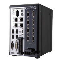
Omron fz5 series User Manual (882 pages)
Vision Sensor Vision System
Brand:
Omron
| Category:
Controller
| Size: 24 MB
Table of Contents
FH/FZ5 Manual Configuration
3
Conventions Used in this Manual
3
Definitions of Basic Terms
4
Table of Contents
9
Terms and Conditions Agreement
15
Meanings of Signal Words
17
Precautions for Safe Use
19
Precautions for Correct Use
20
1 Before Operation
23
Overview
24
Basic Mechanism for Measurements
24
Support for a Variety of Scenes and Measurement Lines
25
Flow of Application
27
Windows
29
Types of Windows
29
Overview of Window Navigation
30
Main Window (Layout 0): Adjustment Window (Default)
31
Main Window (Layout 1): Run Window (Default)
37
Menu List
38
Checking the System Configuration
40
System Configuration
40
Basic Configuration Models
41
Functional Comparison between the FH-Series and FZ5-Series Controllers
44
Saving Settings before Turning off the Power and Restarting
45
Restarting the Controller: [System Restart]
45
Turning off the LCD
46
Initializing the Controller
47
Initializing the Controller: [System Initialization]
47
2 Setting Scenes (Measurement Flows)
49
What Is a Scene
50
Example of a Scene
51
What Is a Scene Group
53
Creating a Scene
54
Editing Processing Units in Scenes
55
Displaying and Checking Processing Branches in a Scene
58
Changing the Scene or Scene Group
62
Changing the Scene
62
Changing Scene Groups
62
Editing Scenes
64
Copying Scenes
64
Deleting Scenes
64
Renaming a Scene and Adding a Description
65
Editing Scene Groups
66
Copying and Deleting Scene Groups
66
Changing the Scene Group Name
67
3 Performing Test Measurement/Starting Operation
69
Adjustment Windows and Run Windows
70
Main Window (Layout 0): Adjustment Window (Default)
70
Main Window (Layout 1): Run Window (Default)
71
Main Window (Layout 1): Changing to the Run Window
71
Main Window (Layout 1): Changing to the Adjustment Window
71
Preparing the Controller and Cameras
72
Camera Setup
72
Preparing a Controller
73
Adjusting the Camera
74
Intelligent Camera (with Lighting)
75
Executing Test Measurements
76
Key Points for Adjustment
77
Stabilizing Measurements
77
Shortening Processing Time
78
Arranging Windows
80
Arranging Window Elements (Layout Modification)
80
Setting the Behavior of Output Signals for each Layout (Layout Settings)
92
Changing Layout Numbers in the Main Window
92
Troubleshooting
93
Arranging the Window Display
94
Changing the Image Mode and Other Display Contents
94
Custom Dialogs
96
Flow of Use
96
Custom Dialog Tool
97
Launching Your Custom Dialog Box
110
Useful Functions for Operation
111
Remeasuring Saved Images
111
Improving Adjustment Efficiency
112
Changing Judgement Conditions Without Stopping Measurement
113
Changing Regions as a Batch [Shift Area]
114
Monitoring Measurement Value Trends
114
Logging Measurement Values and Measurement Images
115
Analyzing Logged Data
123
Clearing Measurement Results
124
Clearing Saved Images
125
Capturing Screen Images
125
Using the Operation Log
127
Operation Log Format
129
Saving Data to an External Device
130
4 Using Tools
133
Using NG Analyzer
134
Layout of NG Analyzer Window
135
Using Method of NG Analyzer
136
Updating the Reference Position
139
Using the User Data Tool
140
Setting Procedure for User Data
140
Creating Scene Group Data for more than 128 Scenes
142
Outputting a List of Scene Data Set Values
145
Downloading Set Values
145
About Downloaded CSV Files
145
Uploading Set Values
147
Saving Image Files to a RAM Disk or External Memory Device
148
Using the Registered Image Manager
150
Registering Images
150
Loading an Image
151
Using Accounts
152
Setting Accounts (Account List)
152
Setting Layout Restrictions
154
Setting User Group Operation Restrictions
155
Saving/Loading/Deleting the Security Settings
156
Changing between User Accounts
159
Logging in
159
Logging out
159
Remotely Operating the Controller (Remote Operation)
160
Overview
160
Operation Environment Condition
161
How to Start
163
Using Communication Command Macro
166
Flow Viewer
167
Custom Dialog Boxes
168
Calibration Support Tool
169
Saving Scene Groups in External Memory
170
5 Optimizing Scenes (Measurement Flows) (Macro Customize Functions)
173
Basic Knowledge for Macro Customize Functions
175
What Are the Macro Customize Functions
175
List of Macro Customize Functions
175
Structure of this Chapter
177
How to Use Macro Customize Functions
178
Components of the Macro Customize Functions
178
Procedures for Using the Macro Customize Functions
179
Components of the Screens and How to Configure Settings
183
Components of the Program Editing Screen
183
Description of the System Status Console Window
187
Description of the Setting Screen for the "Unit Calculation Macro" Processing Item and How to Configure Settings
188
Description of the Setting Screen of the Scene Control Macro Tool and How to Configure Settings
192
Components of the Setting Screen of the Communication Command Macro Tool and How to Configure Settings
194
Description of the Setting Screen of the "Unit Macro" Processing Item and How to Configure Settings
201
Saving and Loading Programs
205
Basic Method for Writing Programs
207
Basic Syntax
207
Constant
210
Variable
211
Operator
215
Expression
217
How to Write Advanced Programs
219
Data Types Related to Processing Units
219
Data Types Related to the System
224
Scope of Data and Save Area
227
State Transitions and Execution Timing
229
Exclusive Control in a Process
236
How to Use the Debug Function
237
Debug Preparations
237
Debug Procedure
240
Checking Why an Error Occurred
240
Starting Debug
242
Identifying the Cause of an Error
243
Removing the Error
246
Exiting Debug
246
Troubleshooting
247
6 Saving and Loading Data
255
Saving Data to the FH/FZ5
256
About Saving Areas
256
External Drive Names
257
Using External Memory Devices (FH and FZ5-11 Only)
258
Shared Folder on a Computer Connected to the Network
258
Saving Settings Data to the Flash Memory and Restarting
259
Saving Settings Data to the Controller RAM Disk or an External Memory Device
260
Saving Logged Images in the Controller Memory (RAM) to a RAM Disk or an External Memory Device
261
Copying or Moving Files between the Controller RAM Disk and an External Memory Device
262
Loading Settings Data from the Controller RAM Disk or an External Memory Device to the Sensor Controller
263
7 Changing the System Environment
265
Setting the Camera Conditions
266
Checking the Camera Connections: [Camera Connection]
266
Setting the Trigger Delay: [Inter-Camera Setting]
266
Setting the SHTOUT Signal: [Output Signal Settings]
267
Setting the Conditions that Are Related to Operation During Measurement
269
Setting the Operation Mode
270
Guidelines for Selecting the Operation Mode
270
Single-Line High-Speed Mode
271
Multi-Line Random-Trigger Mode
275
Non-Stop Adjustment Mode
281
High-Speed Logging Mode
283
Parallel Processing
284
Parallel Processing Settings (Automatic Parallelization)
284
Parallel Processing Settings (Manual Parallelization)
284
Specific Example of Parallel Processing
286
Restrictions
287
Setting Procedures
289
Setting the Operating Environment of the System
293
Setting the Date and Time: [Date-Time Setting]
293
Selecting the Language: [Language Setting]
294
Setting the Fan Rotation Speed: [Fan Control Setting]
294
Setting the Status at Startup: [Startup Settings]
295
Setting the Encoder Trigger: [Encoder Trigger Setting]
298
Setting the STEP Input Detection Pulse Width: [STEP Setting]
299
Setting a Network Drive: [Network Drive Setting]
300
Checking System Information: [System Information]
302
8 Appendices
303
Alignment
304
Overview
304
Execution of Calibration
307
Troubleshooting
313
Alignment
314
Alignment Processing Items
321
Macro Reference
322
Error List
322
List of Reserved Words
324
System Data List
329
List of I/O Modules
343
List of Figure Numbers
368
Model Number List
371
Image Number List
373
List of Sub-Image Numbers
376
Memory Usage Guidance for Processing Items
381
Macro Function List
386
Function-Based Index
397
Macro Command Reference
405
About Lenses
813
Error Messages and Troubleshooting
829
Faq
833
During Start-Up
833
During Operation
833
For Measurement
834
About Parallel Interface
835
Serial Interface (RS-232C/422 Connection)
836
Camera with Lighting Controller
836
Measurement Mechanism
837
Color Processing Mechanism
837
Search Processing Mechanism
838
Edge Detection Measurement
841
Defect Detection Measurement
844
Handling Coordinates
844
Basic Knowledge about Operations
846
Inputting Values
846
Inputting Text
846
Selecting Files and Folders
847
Available Operations in Select File Window
848
Using the Zoom Function
849
Layout of Figure Setting Area
850
Setting Figures
850
Setting Methods
851
About or Setting/Not Setting
857
About Number of Logging Images
858
About Limits on the Number of Image Input Processing Items Used
860
About Max. Number of Loading Images During Multi-Input
861
Character Code Table
862
About Memories Usable with FZ Series
863
Memory Display Image on PLC I/O
864
Operation Log Input Information List
866
Manual Revision History
880
Advertisement
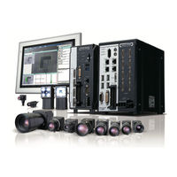
Omron fz5 series User Manual (524 pages)
Brand:
Omron
| Category:
Machine Vision Systems
| Size: 19 MB
Table of Contents
FH/FZ5 Manual Configuration
3
Conventions Used in this Manual
4
Terms and Conditions Agreement
5
Safety Precautions
7
Precautions for Safe Use
7
Precautions for Correct Use
7
Regulations and Standards
7
Table of Contents
9
1 Overview
13
Introduction
14
Confirming the System Configuration
15
System Configuration
15
Communicating with an External Device
16
Basic Control Operations of the Sensor Controller
16
Communication between the Sensor Controller and an External Device
18
Control Methods for the Sensor Controller
19
Communication Protocols for Communication with the Sensor Controller
21
Saving Sensor Controller Data to an External Device
22
Control Methods Using an External Device
24
Control with Control Signals and Status Signals
24
Z342-E1
24
Command/Response Method
27
Data Output after Measurements
28
Setting Procedures for Communications
37
Communications Setup Procedures
37
Communications Protocols and Communications Modules
38
Differences in Specifications Based on the Communications Protocol
39
List of Supported Signals by Communications Protocol
39
Restrictions When Using Different Communication Protocols Simultaneously
41
Models that Are Compatible with the Communications Protocols
42
2 Methods for Connecting and Communicating with External Devices
45
Ethercat Connections (FH-1000 Series/Fh-3000 Series Only)
46
Introduction to Ethercat
46
Structure of CAN Application Protocol over Ethercat (Coe)
49
Ethercat Slave Information Files (ESI Files)
50
Transitions of Communications States
51
Process Data Objects (Pdos)
52
Service Data Objects (Sdos)
55
Communications between an Ethercat Master and Slaves
56
FH-Series Vision Sensor Communications Method When Connected to Ethercat
57
Communications Settings
62
Communications Module Settings (Startup Settings)
64
Communications Specifications Settings
65
Output Data Settings (Processing Item Registration)
68
Ethercat Network Configuration Settings
71
Communications Test
72
I/O Ports by Area (PDO Mapping) and Memory Assignments
73
I/O Signals
78
Measurement Results that You Can Output with Fieldbus Data Output
82
Command List
83
Measurement Trigger Input
86
Command Response Processing
87
Data Output
90
Time Charts
92
Ethercat Troubleshooting
96
Sysmac Error Status
98
Sysmac Device Features
112
Object Dictionary
114
Communicating with PLC Link
164
Communications Processing Flow
164
Communications Setup Procedures
166
Communications Module Settings (Startup Settings)
166
Communications Specifications Settings
168
Output Data Settings (Processing Item Registration)
186
Testing Communications
191
Memory Allocation
194
I/O Signals
197
Output Items
200
Command List
201
Command Response Processing
204
Data Output
207
Time Charts
209
PLC Link Troubleshooting
212
Communicating with Ethernet/Ip
215
Introduction to Ethernet/Ip
215
Data Exchange with Ethernet/Ip
216
Ethernet/Ip Communications
219
Communications Processing Flow
220
Communications Setup Procedures
222
Communications Module Settings (Startup Settings)
223
Communications Specifications Settings
224
Tag Data Link Setting Methods
230
Output Data Settings (Processing Item Registration)
234
Testing Communications
238
Memory Allocation
240
I/O Signals
249
Output Items
252
Command List
253
Command Response Processing
257
Data Output
260
Time Charts
262
Communicating with the Sensor Controller with Ethernet/Ip Message Communications
266
Command Setting Example
269
Ethernet/Ip Troubleshooting
269
Non-Procedure Communications
271
Communications Processing Flow
271
Communications Setup Procedures
272
Communications Module Settings (Startup Settings)
273
Communications Specifications Settings
274
Output Data Settings (Processing Item Registration)
281
Testing Communications
287
Output Items
290
Command Formats
291
Command List
294
Output Format
298
Non-Procedure Communications Troubleshooting
300
Parallel Communications
301
Communications Processing Flow
301
Communications Setup Procedures
303
Communications Module Settings (Startup Settings)
304
Communications Specifications Settings
305
Output Data Settings (Processing Item Registration)
312
Testing Communications
320
I/O Signals
322
Output Items
332
Command Formats
334
Time Charts
338
Parallel Troubleshooting
349
3 Appendices
351
Command Control
352
Parameter Notation Examples for Command Control
352
Details of Commands Used in Ethercat Communication
356
Command List
357
Command Details for PLC Link, Ethernet/Ip, and Ethercat
363
Non-Procedure Command Details
428
Manual Revision History
522
Omron fz5 series Hardware Setup Manual (286 pages)
Vision Sensor
Brand:
Omron
| Category:
Accessories
| Size: 20 MB
Table of Contents
Introduction
3
Intended Audience
3
Applicable Products
3
Relevant Manuals
4
Manual Structure
6
Page Structure
6
Special Information
7
Sections in this Manual
9
Table of Contents
10
Terms and Conditions Agreement
14
Warranty, Limitations of Liability
14
Application Considerations
15
Disclaimers
15
Safety Precautions
16
Precautions for Safe Use
19
Precautions for Correct Use
22
Regulations and Standards
25
All Series
25
FH-1000/2000/3000/5000 Series
26
FH-L Series
27
FZ5 and FZ-L Series
28
Related Manuals
29
Terminology
31
Revision History
36
Confirm the Package
37
Sensor Controller
38
FH-2/FH-3/FH-5 Series
38
10/FH-2-10/FH-3-10/FH-5-10 Series
38
FH-1-20/FH-2-20/FH-3-20/FH-5-20 Series
39
FH-L Series
39
FH-L-10 Series
40
FZ5-12 / FZ5-11 / FZ5-6 / FZ5-8 Series
40
FZ5-L35 Series
41
FZ5-L35-10 Series
41
Sold Separately
42
Cameras and Related
42
Monitor
45
Lighting and Lighting Controller
45
Accessories
46
Cable
47
Software
49
Overview of FH/FZ5 Series
52
Overview of System
52
Basic System of Measurement
52
FH-1000/FH-2000/FH-3000/FH-5000 Series
54
FH-L Series
55
FZ5 Series
55
FZ5-L Series
56
System Configuration
57
FH-1000/2000/3000/5000 Series
57
FH-L Series
58
FZ5-600/FZ5-800/FZ5-1100/FZ5-1200 Series
59
FZ5-L Series
60
Flow of Use Procedure
61
Sensor Controller
65
FH-1000/2000/3000/5000 Series
65
FH-L Series
75
FZ5-600/FZ5-800/FZ5-1100/FZ5-1200 Series
80
FZ5-L Series
80
Sensor Controller
80
FZ5-L Series
81
FZ5-L Series
90
Camera
94
High-Speed Digital CMOS Camera (FH-S Camera Series)
94
Digital CMOS
100
Digital CCD/CMOS Cameras: FZ-S Camera Series
103
High-Speed Digital CCD Cameras : FZ-SH Camera Series
106
Small Digital CCD Cameras: FZ-S Camera Series
107
Intelligent Compact Digital CMOS Camera: FZ-S Camera Series
110
Camera Cable
113
Camera Cables and Right-Angle Camera Cable
113
Bend Resistant Camera Cable and Bend Resistant Right-Angle Camera Cable
114
Long-Distance Camera Cable and Long-Distance Right-Angle Camera Cable
115
Cable Connection Table
116
Cable Extension Units
119
Lens
123
C-Mount Lens for 1/3-Inch Image Sensor
123
C-Mount Lens for 2/3-Inch Image Sensor
124
C-Mount Lens for 1-Inch Image Sensor
125
C-Mount Lens for 4/3-Inch Image Sensor
126
M42-Mount Lens for Large Image Sensor
127
Lenses for Small Camera
127
Vibration and Shock Resistant C-Mount Lens for 2/3-Inch Image Sensor
128
Image Sensor3-66
128
Vibration and Shock Resistant C-Mount Lens for 1-Inch Image Sensor
130
Vibration and Shock Resistant C-Mount Lens for 1.8-Inch Image Sensor
132
3-4-12 Extension Tubes
137
3-4-13 Meaning of Optical Chart
138
Touch Panel Monitor and Cable
152
LCD and Cable
158
Sysmac Studio
161
Handling and Installation Environment
164
All Series
164
FH-1000/2000/3000 Series
166
FH-5000 Series
167
FH-L Series
168
FZ5 Series
169
FZ5-L Series
170
Setup and Wiring
171
When Turning on and off
173
All Series
173
FH-1000/2000/3000/5000 Series
175
FH-L Series
175
FZ5 Series
175
FZ5-L Series
175
Fail-Safe Measures
176
Sensor Controller Installation
177
All Series
177
FH-1000/2000/3000/5000 Series
178
FH-L Series
183
FZ5 Series
193
FZ5-L Series
197
Setup Touch Panel Monitor or Monitor
199
All Series
199
FH-1000/2000/3000/5000 Series
199
FH-L Series
200
FZ5 Series
200
FZ5-L Series
200
Camera Installation
201
All Series
201
FH-1000/2000/3000/5000 Series
202
FH-L Series
203
FZ5 Series
203
FZ5-L Series
204
Insert/Remove SD Memory Card or USB Flash Drive
205
Common in All Series
205
FH-1000/2000/3000/5000/FH-L Series
205
Use by Connecting Software
206
Sysmac Studio FH Tool
206
FZ_FH Remote Operation Tool
206
Simulation Software
206
Installation in a Control Panel
207
All Series
207
FH-1000/2000/3000 Series
209
FH-5000 Series
211
FH-L Series
213
FZ5 Series
221
FZ5-L Series
223
I/O Interface
225
Parallel Interface
226
All Series
226
FH-1000/2000/3000/5000 Series
227
FH-L Series
234
NPN Input/Output for FZ5 Series
241
PNP Input/Output for FZ5 Series
247
FZ5-L Series
253
Other (Parallel Converter Cable)
257
Encoder Interface
268
Ethercat Interface
271
Ethernet Interface
273
FH-1000/2000/3000/5000 Series
274
FH-L Series
276
FZ5 Series
278
FZ5-L Series
279
Serial Interface
281
All Series
281
FH-1000/2000/3000/5000 and FH-L Series
282
FZ5 Series
283
FZ5-L Series
284
Advertisement
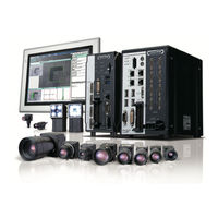
Omron fz5 series Hardware Setup Manual (260 pages)
Vision Sensor
Brand:
Omron
| Category:
Industrial Equipment
| Size: 48 MB
Table of Contents
Introduction
3
Intended Audience
3
Applicable Products
3
Relevant Manuals
4
Manual Structure
6
Page Structure
6
Special Information
7
Sections in this Manual
9
Table of Contents
10
Terms and Conditions Agreement
14
Warranty, Limitations of Liability
14
Application Considerations
15
Disclaimers
15
Safety Precautions
16
Precautions for Safe Use
18
Precautions for Correct Use
21
Regulations and Standards
24
All Series
24
FH-1000 and FH-3000 Series
25
FH-L Series
26
FZ5 and FZ-L Series
27
Related Manuals
28
Terminology
29
Revision History
33
Confirm the Package
35
Sensor Controller
36
FH-3 Series
36
10 / FH-3-10 Series
36
FH-1-20 / FH-3-20 Series
37
FH-L Series
37
FH-L-10 Series
38
FZ5-12 / FZ5-11 / FZ5-60 / FZ5-8 Series
38
FZ5-L35 Series
39
FZ5-L35-10 Series
39
Sold Separately
40
Cameras and Related
40
Monitor
42
Lighting and Lighting Controller
42
Accessories
43
Cable
44
Software
46
Overview of System
48
Basic System of Measurement
48
FH-1000/FH-3000 Series
50
FH-L Series
51
FZ5 Series
51
FZ5-L Series
52
System Configuration
53
FH-1000/FH-3000 Series
53
FH-L Series
54
FZ5-600/FZ5-800/FZ5-1100/FZ5-1200 Series
55
FZ5-L Series
56
Flow of Use Procedure
57
Sensor Controller
60
FH-1000/FH-3000 Series
60
FH-L Series
66
FZ5-600/FZ5-800/FZ5-1100/FZ5-1200 Series
71
FZ5-L Series
81
Camera
85
High-Speed Digital CMOS Camera (FH-S Camera Series)
85
Digital CMOS Cameras: FH-S Camera Series
89
Digital CCD/CMOS Cameras: FZ-S Camera Series
90
High-Speed Digital CCD Cameras : FZ-SH Camera Series
94
Small Digital CCD Cameras: FZ-S Camera Series
95
Intelligent Compact Digital CMOS Camera: FZ-S Camera Series
98
Camera Cable
101
Camera Cables and Right-Angle Camera Cable
101
Bend Resistant Camera Cable and Bend Resistant Right-Angle Camera Cable
102
Long-Distance Camera Cable and Long-Distance Right-Angle Camera Cable
103
Cable Connection Table
104
Cable Extension Units
106
Lens
109
C-Mount Lens for 1/3-Inch Image Sensor
109
C-Mount Lens for 2/3-Inch Image Sensor
110
C-Mount Lens for 1-Inch Image Sensor
111
M42-Mount Lens for Large Image Sensor
112
Lenses for Small Camera
112
Vibration and Shock Resistant C-Mount Lens for 2/3-Inch Image Sensor
113
High-Resolution Telecentric Lens for C-Mount Lens for 2/3-Inch Image Sensor
116
Extension Tubes
118
Meaning of Optical Chart
119
Lighting, Lighting Controller, and Cables
128
Touch Panel Monitor and Cable
129
LCD and Cable
135
Sysmac Studio
138
All Series
140
FH-1000/FH-3000 Series
142
FH-L Series
143
FZ5 Series
144
FZ5-L Series
145
Setup and Wiring
147
When Turning on and off
149
All Series
149
FH-1000/FH-3000 Series
151
FH-L Series
151
FZ5 Series
151
FZ5-L Series
151
Fail-Safe Measures
152
Sensor Controller Installation
153
All Series
153
FH-1000/FH-3000 Series
154
FH-L Series
158
FZ5 Series
168
FZ5-L Series
172
Setup Touch Panel Monitor or Monitor
174
All Series
174
FH-1000/FH-3000 Series
174
FH-L Series
175
FZ5 Series
175
FZ5-L Series
175
Camera Installation
176
All Series
176
FH-L Series
178
FZ5 Series
178
FZ5-L Series
179
Insert SD Memory Card or USB Memory
180
FH-L Series
181
FZ5 Series
181
Use by Connecting Software
182
Sysmac Studio FH Tool
182
FZ_FH Remote Operation Tool
182
Simulation Software
182
Installation in a Control Panel
183
All Series
183
FH-L Series
187
FZ5 Series
195
FZ5-L Series
197
Parallel Interface
200
All Series
200
FH-1000/FH-3000 Series
201
FH-L Series
208
NPN Input/Output for FZ5 Series
215
PNP Input/Output for FZ5 Series
221
FZ5-L Series
227
Other (Parallel Converter Cable)
231
Encoder Interface
242
Ethercat Interface
245
Ethernet Interface
247
FH-1000/FH-3000 Series
248
FH-L Series
250
FZ5 Series
252
FZ5-L Series
253
Serial Interface
255
All Series
255
FH-1000, FH-3000, and FH-L Series
256
FZ5 Series
257
FZ5-L Series
258
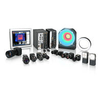
Omron fz5 series Hardware Manual (254 pages)
vision sensor
Brand:
Omron
| Category:
Accessories
| Size: 23 MB
Table of Contents
Introduction
3
Intended Audience
3
Applicable Products
3
Relevant Manuals
4
Manual Structure
6
Page Structure
6
Special Information
7
Sections in this Manual
9
Table of Contents
10
Terms and Conditions Agreement
14
Warranty, Limitations of Liability
14
Safety Precautions
16
Precautions for Safe Use
18
Precautions for Correct Use
21
Regulations and Standards
24
All Series
24
FH-1000 and FH-3000 Series
25
FH-L Series
26
FZ5 and FZ-L Series
27
Related Manuals
28
Terminology
29
Revision History
33
Z366-E1
33
Confirm the Package
35
Sensor Controller
36
10 / FH-3 -10 Series
36
FH-3 Series
36
20 / FH-3 -20 Series
37
FH-L Series
37
FH-L -10 Series
38
FZ5-60 Series
38
FZ5-L35 -10 Series
39
FZ5-L35 Series
39
Sold Separately
40
Cameras and Related
40
Monitor
42
Lighting and Lighting Controller
42
Accessories
43
Cable
44
Software
46
Overview of System
48
Basic System of Measurement
48
FH-1000/FH-3000 Series
50
FH-L Series
51
FZ5 Series
51
FZ5-L Series
52
System Configuration
53
FH-1000/FH-3000 Series
53
FH-L Series
54
FZ5-600/FZ5-1100 Series
55
FZ5-L Series
56
Flow of Use Procedure
57
Sensor Controller
60
FH-1000/FH-3000 Series
60
Configuration
60
FH-L Series
66
FZ5-600/FZ5-1100 Series
71
FZ5-L Series
72
FZ5-L Series
77
Camera
81
High-Speed Digital CMOS Camera (FH-S Camera Series)
81
Digital CMOS Cameras: FH-S Camera Series
85
Digital CCD Cameras: FZ-S Camera Series
86
High-Speed Digital CCD Cameras : FZ-SH Camera Series
89
Small Digital CCD Cameras: FZ-S Camera Series
90
Intelligent Compact Digital CMOS Camera: FZ-S Camera Series
93
Camera Cable
96
Camera Cables and Right-Angle Camera Cable
96
Bend Resistant Camera Cable and Bend Resistant Right-Angle Camera Cable
97
Long-Distance Camera Cable and Long-Distance Right-Angle Camera Cable
98
Cable Connection Table
99
Cable Extension Units
101
Lens
104
C-Mount Lens for 1/3-Inch Image Sensor
104
C-Mount Lens for 2/3-Inch Image Sensor
105
C-Mount Lens for 1-Inch Image Sensor
106
M42-Mount Lens for Large Image Sensor
107
Lenses for Small Camera
107
Vibration and Shock Resistant C-Mount Lens for 2/3-Inch Image Sensor
108
High-Resolution Telecentric Lens for C-Mount Lens for 2/3-Inch Image Sensor
111
Extension Tubes
113
Meaning of Optical Chart
114
Lighting, Lighting Controller, and Cables
122
Touch Panel Monitor and Cable
123
Connection Example
126
LCD and Cable
129
Front View
130
Sysmac Studio
132
All Series
134
FH-1000/FH-3000 Series
136
FH-L Series
137
FZ5 Series
138
FZ5-L Series
139
Setup and Wiring
141
When Turning on and off
143
All Series
143
FH-1000/FH-3000 Series
144
FH-L Series
144
FZ5 Series
144
FZ5-L Series
144
Fail-Safe Measures
145
Sensor Controller Installation
146
All Series
146
FH-1000/FH-3000 Series
147
FH-L Series
151
FZ5 Series
161
Setup Touch Panel Monitor or Monitor
166
All Series
166
FH-1000/FH-3000 Series
166
FH-L Series
167
Camera Installation
168
All Series
168
FH-L Series
170
FZ5 Series
170
FZ5-L Series
171
Insert SD Memory Card or USB Memory
172
FH-L Series
173
FZ5 Series
173
Use by Connecting Software
174
Sysmac Studio FH Tool
174
FZ_FH Remote Operation Tool
174
Simulation Software
174
Installation in a Control Panel
175
All Series
175
FH-1000/FH-3000 Series
178
FH-L Series
180
FZ5 Series
188
FZ5-L Series
190
Parallel Interface
194
All Series
194
FH-1000/FH-3000 Series
195
FH-L Series
202
NPN Input/Output for FZ5 Series
209
PNP Input/Output for FZ5 Series
215
FZ5-L Series
221
Other (Parallel Converter Cable)
225
Encoder Interface
236
Ethercat Interface
239
Ethernet Interface
241
FH-1000/FH-3000 Series
242
FH-L Series
244
FZ5 Series
246
FZ5-L Series
247
Serial Interface
249
All Series
249
FH-1000, FH-3000, and FH-L Series
250
FZ5 Series
251
FZ5-L Series
252
Omron fz5 series Connection Manual (54 pages)
CJ Series EtherNet/IP
Brand:
Omron
| Category:
Machine Vision Systems
| Size: 2 MB
Table of Contents
Table of Contents
3
1 Related Manuals
4
2 Terms and Definitions
5
3 Precautions
6
4 Overview
7
5 Applicable Devices and Device Configuration
8
Applicable Devices
8
Device Configuration
9
6 Ethernet/Ip Settings
11
Parameters
11
Allocating the Tag Data Links
13
7 Ethernet/Ip Connection Procedure
15
Work Flow
15
Setting up the FH Sensor Controller
16
Setting up the PLC
22
Setting up the Network
31
Checking the Ethernet/Ip Communications
45
8 Initialization Method
50
Initializing the PLC
50
Initializing the FH Sensor Controller
51
9 Revision History
52
Omron fz5 series Connection Manual (20 pages)
EtherNet/IP Vision System
Brand:
Omron
| Category:
Computer Hardware
| Size: 0 MB
Table of Contents
Table of Contents
3
Related Manuals
4
Terms and Definitions
5
Precautions
6
Overview
7
Applicable Devices and Device Configuration
8
Applicable Devices
8
Device Configuration
9
Ethernet/Ip Settings
10
Ethernet/Ip Communications Parameters
10
Allocating the Tag Data Links
10
Ethernet/Ip Connection Procedure
13
Work Flow
13
Setting up the FZ5 Sensor Controller
14
Setting up the PLC
19
omron fz5 series Installation Instructions Manual (2 pages)
Image Processing System
Brand:
omron
| Category:
Laboratory Equipment
| Size: 0 MB
Table of Contents
Precautions for Compliance with UL Standards and CSA Standards
1
Wiring for Power Input
1
Environment
1
Mounting
1
I/O Connector
2
Connection Example
2
Camera Connector
2
Terminal Connect
2
Handling the Output Common Terminals
2
Advertisement
Related Products
Omron fz5-6 series
Omron fz5-11 series
Omron fz5-l35 series
Omron FZ2-3 Series
Omron FZ3-H35-10
Omron FZ3-75-10
Omron FZ3-H70-10
Omron FZ3-95-10
Omron FZD-50-10
Omron FZD-55-10
Omron Categories
Blood Pressure Monitor
Controller
Accessories
Switch
Inverter
More Omron Manuals
Login
Sign In
OR
Sign in with Facebook
Sign in with Google
Upload manual
Upload from disk
Upload from URL