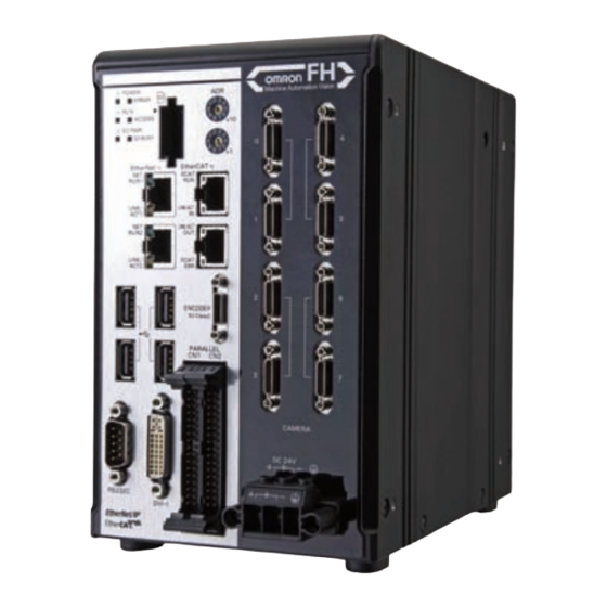
Omron SYSMAC FH Series User Manual
Vision sensor vision system
Hide thumbs
Also See for SYSMAC FH Series:
- User manual (647 pages) ,
- Hardware setup manual (244 pages) ,
- Operation manual (176 pages)


Need help?
Do you have a question about the SYSMAC FH Series and is the answer not in the manual?
Questions and answers