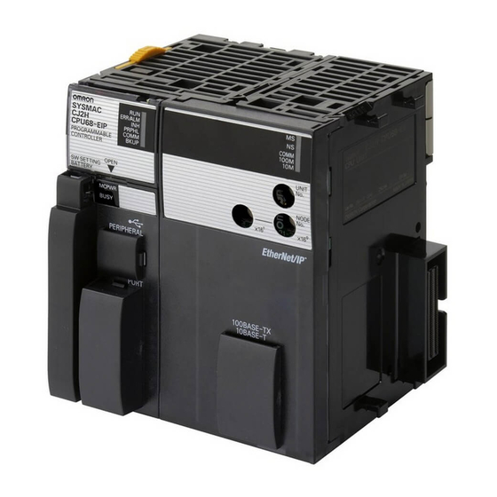
Omron CJ Series Connection Manual

Omron CJ Series Connection Manual

Ethernet/ip vision system
Hide thumbs Also See for CJ Series:

Advertisement

Quick Links

No.FST-ZTH130088A
CJ Series
EtherNet/IP
OMRON Corporation
Vision System
FZ5 Series
Industrial automation
Elincom Group
European Union: www.elinco.eu
Russia: www.elinc.ru
TM
Connection Guide
P588-E1-01

Advertisement

Table of Contents
loading

Summary of Contents for Omron CJ Series

  • Page 1 No.FST-ZTH130088A CJ Series EtherNet/IP Connection Guide OMRON Corporation Vision System FZ5 Series P588-E1-01 Industrial automation Elincom Group European Union: www.elinco.eu Russia: www.elinc.ru...
  • Page 2 About Intellectual Property Rights and Trademarks Microsoft product screen shots reprinted with permission from Microsoft Corporation. Windows is a registered trademark of Microsoft Corporation in the USA and other countries. ODVA and EtherNet/IP are trademarks of ODVA. Company names and product names in this document are the trademarks or registered trademarks of their respective companies.
  • Page 3: Table Of Contents

    Table of Contents Related Manuals ..................1 Terms and Definitions ................. 2 Precautions ....................3 Overview ...................... 4 Applicable Devices and Device Configuration ........5 5.1. Applicable Devices ................5 5.2. Device Configuration ................6 EtherNet/IP Settings ..................7 6.1. EtherNet/IP Communications Parameters ..........
  • Page 4: Related Manuals

    1.Related Manuals 1. Related Manuals The table below lists the manuals related to this document. To ensure system safety, make sure to always read and heed the information provided in all Safety Precautions, Precautions for Safe Use, and Precaution for Correct Use of manuals for each device which is used in the system.
  • Page 5: Terms And Definitions

    The data unit consisting of two or more tags for the data exchange is called a tag set. Up to eight tags can be configured per tag set for OMRON controllers. Tag data link In the EtherNet/IP, the tag and tag set can be exchanged cyclically between nodes without using the user program.
  • Page 6: Precautions

    (4) It is prohibited to copy, to reproduce, and to distribute a part or the whole of this document without the permission of OMRON Corporation. (5) The information contained in this document is current as of December 2013. It is subject to change without notice for improvement.
  • Page 7: Overview

    4. Overview This document describes the procedure for connecting the Vision System (FZ5 Sensor Controller + Camera) (FZ5 series) of OMRON Corporation (hereinafter referred to as OMRON) with CJ-series Programmable Controller + Ethernet/IP Unit (hereinafter referred to as the PLC), and the procedure to check their connection.
  • Page 8: Applicable Devices And Device Configuration

    This document describes the procedure to establish the network connection. Except for the connection procedure, it does not provide information on operation, installation or wiring method. It also does not describe the functionality or operation of the devices. Refer to the manuals or contact your OMRON representative.
  • Page 9: Device Configuration

    (Built-in EtherNet/IP port) (CX-One, installed, OS: Windows 7 ) cable USB cable FZ-M08 Switching hub FZ-VS W4S1-05C FZ-SC2M Manufacturer Name Model Version OMRON CPU Unit CJ2M-CPU32 Ver.2.0 (Built-in EtherNet/IP port) (Ver.2.12) OMRON Power Supply Unit CJ1W-PA202 OMRON Switching hub W4S1-05C Ver.1.00 OMRON...
  • Page 10: Ethernet/Ip Settings

    6.EtherNet/IP Settings 6. EtherNet/IP Settings This section describes the specifications such as communication parameters and tag data link that are set in this document. 6.1. EtherNet/IP Communications Parameters The communications parameter required connecting the PLC and the FZ5 Sensor Controller via EtherNet/IP is given below.
  • Page 11 6.EtherNet/IP Settings ■ Details on output area 14 13 12 11 10 0 Meaning D10100 ERCLR XEXE STEP EXE Control output (2 words) D10101 D10102 Command code CMD-CODE (2 words) D10103 D10104 D10105 Command D10106 CMD-PARAM parameter D10107 (6 words max) D10108 D10109 EXE: Command Request Bit: Turned ON to execute a command.
  • Page 12 6.EtherNet/IP Settings ■ Details on input area 15 14 13 12 11 0 Meaning D10100 XWAIT XBUSY XFLG RUN OR BUSY FLG Control output (2 words) D10101 GATE D10102 Command code CMD-CODE (2 words) D10103 D10104 Response code RES-CODE (2 words) D10105 D10106 Response data...
  • Page 13: Ethernet/Ip Connection Procedure

    7.EtherNet/IP Connection Procedure 7. EtherNet/IP Connection Procedure This section describes the procedure for connecting the FZ5 Sensor Controller to the PLC via EtherNet/IP. This document explains the procedures for setting up the PLC and the FZ5 Sensor Controller from the factory default setting. For the initialization, refer to Section 8 Initialization Method. 7.1.
  • Page 14: Setting Up The Fz5 Sensor Controller

    7.EtherNet/IP Connection Procedure 7.2. Setting Up the FZ5 Sensor Controller Set up the FZ5 Sensor Controller. 7.2.1. Parameter Settings Set the parameters for the FZ5 Sensor Controller. Connect the Camera, Monitor, USB connected mouse, and the LAN cable to the FZ5 Sensor Controller.
  • Page 15 7.EtherNet/IP Connection Procedure Select System Settings-Startup-Startup setting from the tree. The Language setting Dialog Box is displayed. Select the Communication Tab. The Communication module select Dialog Box is displayed. Select EtherNet/IP from the Fieldbus pull-down list. Then, click the Apply Button. Click the Close Button to close the System Settings Dialog Box.
  • Page 16 7.EtherNet/IP Connection Procedure Select System restart from the Function Menu. The System restart Dialog Box is displayed. Check the contents and click the OK Button. After restarting, select System Settings from the Tool Menu. Select System Settings - Communication - Ethernet(Normal(UDP)) from the tree.
  • Page 17 7.EtherNet/IP Connection Procedure The dialog box on the right is displayed. Select the Use the following IP address Option for Address setting and set the following values. IP address: 192.168.250.2 Subnet mask: 255.255.255.0 * To change a value, click the * How to change values.
  • Page 18 7.EtherNet/IP Connection Procedure When a value is changed, the Apply Button is displayed. Click the Apply Button. While the setting is being processed, the dialog box on the right is displayed. After the dialog box disappears, click the Close Button to close the System Settings Dialog Box.
  • Page 19: Setting Up The Plc

    7.EtherNet/IP Connection Procedure 7.3. Setting Up the PLC Set up the PLC. 7.3.1. Hardware Settings Set the hardware switches on the EtherNet/IP Unit and wire the network. Precautions for Correct Use Make sure that the power supply is OFF when you perform the setting up. Make sure that the power supply to the PLC is OFF.
  • Page 20 7.EtherNet/IP Connection Procedure Set the Node address setting With the FINS communications service, when there are multiple EtherNet/IP Units connected to the Ethernet network, the EtherNet/IP Units are identified switches to the following default by node addresses. Use the node address switches to set the node address settings.

Table of Contents