Sign In
Upload
Manuals
Brands
Anritsu Manuals
Measuring Instruments
VNA Master MS2024B
Anritsu VNA Master MS2024B Analyzer Manuals
Manuals and User Guides for Anritsu VNA Master MS2024B Analyzer. We have
3
Anritsu VNA Master MS2024B Analyzer manuals available for free PDF download: Manual, Maintenance Manual, User Manual
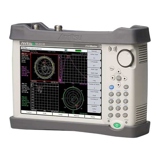
Anritsu VNA Master MS2024B Manual (256 pages)
Vector Network Analyzer for Anritsu RF and Microwave Handheld Instruments
Brand:
Anritsu
| Category:
Measuring Instruments
| Size: 23.54 MB
Table of Contents
Table of Contents
3
Chapter 1-General Information
11
Introduction
11
Contacting Anritsu
11
VNA Master Models
12
Identifying the Connections
13
Chapter 2-VNA Display Overview
15
Introduction
15
Powerful Display Capabilities
15
Flexible Features for Displaying Results
15
Active Trace
16
Changing the Active Trace
16
Touch Screen Trace Features
17
Trace Description
17
Example Measurement Displays
18
Vector Network Analyzer MG PN: 10580-00289 Rev. K
19
Marker and Limit Capabilities
21
Marker Description
21
Selecting the Readout Style for each Marker
21
Displaying Markers on the Screen
21
Setting up Delta Markers
22
Setting up Limits
22
Markers on a Touch Screen
22
Trace Math Capabilities
23
Chapter 3-VNA Fundamentals
25
Introduction
25
Option 16 (S412E LMR Master)
25
S-Parameters
26
Additional Examples
26
VNA Master Architecture
27
Calculating and Displaying S-Parameters
30
Extracting more Information by Using Markers
32
How Bias Is Generated
32
Chapter 4-VNA Measurements
33
Introduction
33
Select Measurement Type - VNA Versus Field
33
Touch Screen Trace Features
33
Markers on a Touch Screen
33
1-Port Cable Measurement
33
Setup Considerations
33
Measurement Readout and Interpretation
34
1-Port Smith Chart Tuning Example
37
2-Port Filter Measurement
39
Introduction
39
Setup Considerations
39
Measurement Readout and Interpretation
39
2-Port Amplifier Measurement
42
Introduction
42
Setup Considerations
42
Measurement Readout and Interpretation
42
Waveguide Considerations
45
Introduction
45
Setup Considerations
45
Measurement Readout and Interpretation
46
Calibration Considerations
48
Ms20Xxb 1-Path 2-Port Calibration
49
Ms20Xxc Full 2-Port Calibration
50
Calibration Data and Indications
51
Cal Type
52
Chapter 5-Field Measurements
53
Introduction
53
Options
53
Field Measurements View Setting
53
Select Measurement Type - Field Versus VNA
53
Touch Screen Trace Features
53
Markers on a Touch Screen
53
Measurement Setup
54
Setting the Frequency Range
54
Setting the Start and Stop Frequencies
55
Setting Data Points
55
Calibration
55
Graph Type Selector List Box
56
Field Measurements View Versus VNA Measurements View
56
Insertion Loss in Display Type Single
57
VSWR and Return Loss in Display Type Dual
58
Insertion Loss and Return Loss in Display Type Overlay
59
Field View Menus
60
VNA Measurements
60
Return Loss/Vswr
61
Cable Loss
64
Distance-To-Fault (DTF)
66
DTF Measurement Calculations
69
5-10 Phase Measurements
70
1-Port Phase Measurement
70
2-Port Phase Measurement
71
Smith Chart
73
Smith Chart Measurement
73
5-12 Log Mag Display Types
75
Typical Log Magnitude Measurement
75
Dual Channel Filter Tuning Measurement
78
Chapter 6-VNA View Menus
81
Introduction
81
VNA Key Functions
81
Domain Setup Menus
83
Freq Menu
84
Setup Domain Menu
85
Time Menu
86
Time Info List Box
87
Windowing Menu
88
Distance Setup Menu
89
Additional Dist Setup Menu (Coax)
90
Cable List Menu (Coax)
91
Additional Dist Setup Menu (Waveguide)
92
Distance Info List Box for Cable
93
Distance Info List Box for Waveguide
93
FGT Menu
94
Gate Menu
95
Gate Setup Menu (Continued)
96
Gate Shape Menu
97
Calibration Menus
98
Calibration Menu
99
Calibration Menu with Thru
105
Calibration Line Setup Menu
107
Existing Calibration Information List Box
108
Additional Calibration Considerations
108
DUT Port Setup Menu (Coax)
109
Cal Kit Definition Menus for Coax
110
DUT Connector Selector List Box for Coax
111
SOLT - Coax Menu
112
DUT Port Setup Menu (Waveguide)
113
Cal Kit Definition Menus for Waveguide
114
DUT Connector Selector List Box for Waveguide
115
SOLT - WG Menu
116
Calibration Types
117
Limit Menus
118
Limit Menu
119
Limit Edit Menu
120
Marker Menus
121
Marker Menu
122
Marker Search Menu
123
Readout Format Menu
124
Measurement Menus
125
Measure Menu
126
S-Parameter List Box
127
S-Parameter Menu
128
Domain Menu
129
Low Pass Mode Menu
130
Band Pass Mode Menu
130
Number of Traces Menu
131
Trace Format Menu
132
Sweep Menu - Ms20Xxc
133
Sweep Menu - Ms20Xxb and S412E
134
Configure Ports Menu
135
Bias Tee Setup Menu
136
Bias Tee Menu (Ms20Xxc Only)
137
Source Power Menu (Ms20Xxc Only)
138
Source Power Menu (Ms20Xxb and S412E Only)
138
Preset Menu
139
Scale Menu
140
Smith Scale Menu
141
Polar Scale Menu
142
System Menus
143
Application Options Menu (VNA Mode)
144
Application Options Menu (SPA Mode) VNA Master
145
Application Options Menu (SPA Mode) LMR Master
146
Time Domain Options Menu
147
Trace Menu
148
Trace Math Menu
149
Introduction
151
Chapter 7 -Field View Menus
152
Field View Menu Group (Field View)
152
Field View Frequency Menus
153
Freq/Dist Menu (Distance-Based)
154
Distance Menus
155
DTF Setup Menu
156
Cable List Menu
157
Windowing Menu
158
Scale Menus
159
Scale Menu
160
Scale Menu – Dual or Overlay
161
Sweep Menus
162
Sweep Menu
163
Avg/Smooth Menu
164
Measure Menus
165
Measure Menu – Dual
166
Marker Menu
167
Calibration Menu
168
Application Options Menu
169
Introduction
171
Chapter 9 -Distance Domain
172
VNA Master Implementation
172
Time Domain – Impulse Response
175
Step Response Versus Impulse Response
176
Frequency Gated by Time
179
Waveguide with Dispersion Compensation
181
Phasor Impulse
183
Windowing
185
In the Additional Dist Setup Submenu:
186
Time and Distance Information
187
Introduction
189
Chapter 8 -Time Domain, Option 2
190
VNA Master Implementation
190
Windowing
192
Distance Information
194
Introduction
195
How Bias Is Generated
196
Chapter 10 -Bias Tee, Option 10
199
Bias Tee When Making 2-Port Gain Measurements
199
Bias Tee Menus (Ms20Xxc, MS2026B, and MS2028B)
201
Bias Tee Setup Menu
202
Bias Tee Menu
203
Bias Tee Menus (Field Measurements View)
204
Bias Tee Setup Menu
205
Bias Tee Menus (Ms20Xxb and S412E in VNA View)
206
Introduction
207
Chapter 11 -Vector Voltmeter, Option 15
208
Getting Started
208
Using Vector Voltmeter Mode for the First Time
209
How the VVM Function Works
210
Simple Measurement Using CW Display
211
Calibration Correction
212
Relative Measurements Using CW Display
216
Measurements Using Comparison Table Display
218
Vector Voltmeter Menus
220
Table Menu
221
Save/Recall Menu
222
Introduction
223
Chapter 12 -Balanced Ports, Option 77
225
Typical Measurements
225
A-1 Vector Network Analyzer Formulas
229
Appendix A-Formulas
230
Propagation
230
B-1 Introduction
231
Appendix B-Windowing
232
Rectangular Windowing
232
Nominal Side Lobe Windowing
233
Low Side Lobe Windowing
234
Minimum Side Lobe Windowing
235
C-1 Introduction
237
C-3 Self Test or Application Self Test Error Messages
238
Application Self Test Results Window — VNA
240
Application Self Test Results Window — SPA
241
C-4 Operation Error Messages
242
Appendix C-Error Messages
243
PMON PLD Fail
243
Bias Tee State Cannot be Changed During Calibration
244
Limit Is Not Available for this Graph Type
245
Advertisement
Anritsu VNA Master MS2024B Maintenance Manual (150 pages)
Compact Handheld Vector Network Analyzer with Spectrum Analyzer
Brand:
Anritsu
| Category:
Measuring Instruments
| Size: 13.77 MB
Table of Contents
Safety Symbols
3
Table of Contents
5
Chapter 1-General Information
11
Product Description
12
Frequency Ranges
12
Standard Accessories
12
Related Documents
13
Options
13
Anritsu Customer Service Centers
13
Recommended Test Equipment
14
Vector Network Analyzer Test Equipment
14
Spectrum Analyzer Test Equipment
15
Instrument Options Test Equipment
16
Replaceable Parts and Assemblies
17
Performance Verification Procedures
20
Chapter 2-VNA Performance Verification
23
Frequency Accuracy
23
Equipment Required
23
Procedure
23
Transmission Dynamic Range
24
Equipment Required
24
Procedure
24
Return Loss Measurement Accuracy Verification
25
Equipment Required
25
Procedure
25
Chapter 3-Spectrum Analyzer Performance Verification
27
Residual Spurious Response
28
Equipment Required
28
Procedure
28
Displayed Average Noise Level (DANL)
30
Equipment Required
30
Procedure
30
Frequency Accuracy
32
Equipment Required
32
Related Tests
33
Single Side Band (SSB) Phase Noise
34
Equipment Required
34
Procedure
34
Spurious Response (Second Harmonic Distortion)
36
Procedure
36
Input Related Spurious (IRS) Signals
39
Equipment Required
39
Procedure
39
Resolution Bandwidth Accuracy
43
Equipment Required
43
Procedure
43
Amplitude Accuracy
46
50 Mhz Amplitude Accuracy Verification
46
Equipment Required
46
Procedure
46
Amplitude Accuracy Across Frequency Verification
50
Equipment Required
50
Procedure
50
Third Order Intercept (TOI)
56
Procedure
56
Chapter 4-Options Performance Verification
61
VNA Mode Bias Tee (Option 10) Operational Check
62
Equipment Required
62
Procedure
62
GPS (Option 31) Operational Check
64
Equipment Required
64
Procedure
64
Spectrum Analyzer Frequency Accuracy with GPS on
66
Equipment Required
66
Procedure
66
Chapter 5-Battery Information
69
Introduction
69
Battery Pack Removal and Replacement
70
Battery Pack Information
72
Chapter 6-Removal And Replacement
73
Figures of Instrument Construction
73
Removal and Replacement Instructions
74
Internal Anatomy of All Four VNA Master Models
75
First Step for Opening the Case
75
Screws on Case Back
76
Basic Case Parts
77
Ms20Xxb Instrument Overview
78
Internal Anatomy of Ms202Xb
79
Ms202Xb Separating Case Back from Case Front
79
Ms202Xb Parts in Case Front
80
Ms202Xb Connector Panel
81
Internal Anatomy of Ms203Xb
82
Ms203Xb Separating Case Back from Case Front
82
Ms203Xb Parts in Case Front
83
Ms203Xb Connector Panel
84
Disassembly Sequence Overview
85
Opening the Instrument Case
86
PCB Assembly Replacement (Ms202Xb and Ms203Xb)
89
SPA Assembly Replacement
91
PCB Assembly out of Case
92
PCB Cable Connections
94
GPS (Option 31) Replacement
96
6-10 Ethernet PCB Assembly (Option 411) Replacement
98
Ethernet PCB Assembly
99
Main/Vna PCB Assembly Replacement
100
Section 6-6 "Opening the Instrument Case
100
Section 6-9 "GPS (Option 31) Replacement
100
Section 6-11 "Main/Vna PCB Assembly Replacement
100
6-12 Main/Vna/Dsp PCB Assembly Replacement
101
Section 6-12 "Main/Vna/Dsp PCB Assembly Replacement
101
6-13 Fan Assembly Replacement
102
Section 6-13 "Fan Assembly Replacement
102
6-14 LCD Assembly Replacement
104
Section 6-14 "LCD Assembly Replacement
104
6-15 LCD Backlight PCB Removal and Replacement
107
Section 6-15 "LCD Backlight PCB Removal and Replacement
107
6-16 Keypad and Keypad PCB Replacement
108
Section 6-16 "Keypad and Keypad PCB Replacement
108
6-17 Touch Screen Replacement
109
Section 6-17 "Touch Screen Replacement
109
Chapter 7-Troubleshooting
111
Turn-On Problems
111
Instrument Cannot Boot up
111
Instrument Cannot Complete Boot-Up
111
Instrument Boots with no Display
112
Boot-Up Self Test Fails
112
Operating Problems
112
Battery Pack Charging Problems
112
Touch Screen Problems
112
Vector Network Analyzer Problems
112
Spectrum Analyzer Problems
113
Option 10, VNA Bias Tee Problems
113
Option 31, GPS Problems
113
Other Issues
114
Appendix A-Test Records
115
Introduction
115
A-1 Introduction
115
MS2024B Test Record
116
VNA Frequency Accuracy
116
VNA Transmission Dynamic Range
116
VNA Return Loss Measurements Accuracy
116
MS2025B Test Record
117
VNA Frequency Accuracy
117
VNA Transmission Dynamic Range
117
VNA Return Loss Measurements Accuracy
117
MS2034B Test Record
118
VNA Frequency Accuracy
118
VNA Transmission Dynamic Range
118
VNA Return Loss Measurements Accuracy
118
Spectrum Analyzer Residual Spurious Response
118
Spectrum Analyzer Displayed Average Noise Level (DANL
119
Spectrum Analyzer Frequency Accuracy
119
Spectrum Analyzer Frequency Accuracy (Option 31, GPS
119
Spectrum Analyzer Single Side Band (SSB) Phase Noise
120
Spectrum Analyzer Spurious Response (Second Harmonic Distortion
120
Spectrum Analyzer Input Related Spurious (IRS) Signals
120
Spectrum Analyzer Resolution Bandwidth Accuracy
121
Spectrum Analyzer Amplitude Accuracy
122
Spectrum Analyzer Amplitude Accuracy (Continued
123
Spectrum Analyzer Amplitude Accuracy (Continued
125
Spectrum Analyzer Amplitude Accuracy (Continued
126
Spectrum Analyzer Amplitude Accuracy (Continued
127
Third Order Intercept
128
MS2035B Test Record
129
VNA Frequency Accuracy
129
VNA Transmission Dynamic Range
129
VNA Return Loss Measurements Accuracy
129
Spectrum Analyzer Residual Spurious Response
130
Spectrum Analyzer Displayed Average Noise Level (DANL
131
Spectrum Analyzer Frequency Accuracy
132
Spectrum Analyzer Frequency Accuracy (Option 31, GPS
132
Single Side Band (SSB) Phase Noise
132
Spectrum Analyzer Spurious Response (Second Harmonic Distortion
133
Spectrum Analyzer Input Related Spurious (IRS) Signals
133
Spectrum Analyzer Resolution Bandwidth Accuracy
134
Spectrum Analyzer Amplitude Accuracy
135
Spectrum Analyzer Amplitude Accuracy (Continued
136
Spectrum Analyzer Amplitude Accuracy (Continued
137
Spectrum Analyzer Amplitude Accuracy (Continued
138
Spectrum Analyzer Amplitude Accuracy (Continued
139
Spectrum Analyzer Amplitude Accuracy (Continued
140
Spectrum Analyzer Amplitude Accuracy (Continued
141
Third Order Intercept
142
B-2 T2904 Test Fixture Schematic
143
B-3 T3377 Test Fixture Schematic
144
B-4 T3536 Test Fixture Schematic
145
Troubleshooting
148
Anritsu VNA Master MS2024B User Manual (137 pages)
VNA Master, Handheld Compact Vector Network Analyzer
Brand:
Anritsu
| Category:
Measuring Instruments
| Size: 12.06 MB
Table of Contents
Safety Symbols
8
Table of Contents
10
Chapter 1-General Information
16
Introduction
16
Contacting Anritsu
16
Anritsu Service Centers
16
Additional Documents
17
VNA Master Specifications
17
Available Models and Accessories
17
Identifying the Connections
18
General Description
19
Soft Carrying Case
20
1-10 Tilt Bail Stand
21
Preventive Maintenance
22
1-12 Calibration Requirements - Vector Network Analyzer
22
1-13 Annual Verification
23
1-14 ESD Cautions
23
1-15 Battery Replacement
24
1-16 Secure Environment Workplace
26
VNA Master Memory Types
26
Erase All User Files in Internal Memory
26
Recommended Usage in a Secure Environment
27
Chapter 2-Instrument Overview
28
Introduction
28
Turning on the VNA Master
28
Front Panel Overview
30
Front Panel Keys
31
Touch Screen Keys
34
Keypad Menu Keys (1 to 9)
34
Touch Points
34
Touch Screen Calibration
34
LED Indicators
35
Display Overview
36
Display Settings
37
Test Panel Connector Overview
39
MS2024B and MS2025B
39
MS2034B and MS2035B
40
External Power
40
USB Interface - Type a
41
USB Interface - Mini-B
41
Ethernet Interface (Option 411)
41
Headset Jack
41
Connector Care
42
Connecting Procedure
42
Disconnecting Procedure
42
VNA Master Connectors
43
External Trigger in (50 Ohm)
43
External Reference in (50 Ohm)
43
RF in (50 Ohm)
43
GPS Antenna Connector (Option 31)
43
VNA Port-1 (50 Ohm)
43
VNA Port-2 (50 Ohm)
44
Symbols and Indicators
44
Battery Symbols
44
Additional Symbols
45
Data Entry
46
Numeric Values
46
Parameter Setting
46
Text Entry
47
2-10 Mode Selector Menu
48
Chapter 3-Quick Start Guide
50
Introduction
50
Measurement Mode Selection
50
Vector Network Analyzer
51
Selecting the Measurement Type
51
Setting the Frequency
51
Setting the Scale
52
Turning on Markers
52
Peak and Valley Search Markers
52
Find Marker Value
53
Setting up Delta Markers
53
Setting a Single Limit Line
54
Setting up Distance Domain (Option 501)
55
Calibration Considerations
55
Cal Type
58
Spectrum Analyzer
58
Set Start and Stop Frequencies
58
Enter the Center Frequency
58
Select a Signal Standard
58
Set the Measurement Bandwidth
58
Set the Amplitude
59
Power Offset Set up for Compensating External Loss
59
Set the Span
59
Single Limit Line
60
Create a Limit Envelope
60
Setting up Markers
61
Select a Smart Measurement Type
62
Saving Measurements
63
Chapter 4-File Management
64
Introduction
64
File Types
64
Managing Files
65
Save Files
65
Save Dialog Box
66
Quick Name Keys
66
Recall Files
67
Recall Dialog Box
67
Copy Files
68
Delete Files
69
Delete Dialog Box
69
File Menu Overview
70
File Menu
71
Save Menu
72
Save Location Menu
73
Save on Event Menu
74
Recall Menu
75
Copy Menu
76
Delete Menu
77
Chapter 5-System Operations
78
Introduction
78
System Menu Group Overview
79
System Menu
80
System Options Menu
81
System Options 2/2 Menu
82
Application Options Menu (VNA Mode)
83
Application Options Menu (SPA Mode)
84
Mode (Meas Gain Range) Menu (VNA Mode)
85
Display Settings Menu
86
Reset Menu
87
Preset Menu
88
5-10 Power on Self Test
89
Updating the VNA Master Firmware
89
Chapter 6-GPS (Option 31)
92
Introduction
92
Activating the GPS Feature
92
Saving and Recalling Traces with GPS Information
94
Saving Traces with GPS Information
94
Recalling GPS Information
94
GPS Menu
94
GPS Info
95
Chapter 7-Bias Tee (Option 10)
96
Overview
96
Chapter 8-Anritsu PC Software Tools
100
Introduction
100
Anritsu Tool Box
100
Line Sweep Tools
101
Master Software Tools
102
Easymap Tools
103
Appendix A-Supplemental Documentation
104
Introduction
104
A-1 Introduction
104
B-1 Introduction
106
Appendix B-Signal Standards
110
Appendix C-Error Messages
110
Introduction
110
Reset Options
110
Reset Via Instrument Menus
110
Reset from off Condition
110
Self Test or Application Self Test Error Messages
110
Self Test
110
C-1 Introduction
110
Application Self Test Results Window - VNA
112
Application Self Test (Vector Network Analyzer Mode Only
112
Application Self Test Results Window - SPA
113
Operation Error Messages
114
Fan Failure
114
High Temp Warning
114
Operation Not Permitted in Recall Mode
114
PMON PLD Fail
115
Power Supply
115
Error Saving File. General Error Saving File
115
Vector Network Analyzer Specific Warning Messages
115
Bias Tee Cannot be Enabled for Start Freq < 2Mhz
115
Bias Tee Is Not Allowed for Start Freq < 2Mhz
115
Changing Source Power
115
No Valid Calibration to Change Correction
115
Cannot Continue with Calculating
115
Bias Tee State Cannot be Changed During Calibration
116
Turning Bias Tee to off
116
Calibration will be Lost after Change
116
Changes Not Allowed During Calibration
116
Option 10 (Bias Tee) Not Enabled
116
No External Reference Signal Detected
116
Limit Is Not Available for this Graph Type
116
Appendix D-Tower Mounted Amplifiers
118
Introduction
118
D-1 Introduction
118
Appendix E-Coaxial Cable Technical Data
120
E-1 Coaxial Cable Technical Data
120
Appendix F-Lan and DHCP
124
Introduction
124
F-1 Introduction
124
F-2 Ethernet Configuration
125
Ethernet Config
126
Ethernet Menu
127
F-3 Using DHCP
128
Example 2
129
Advertisement
Advertisement
Related Products
Anritsu VNA Master MS2025B
Anritsu MS2024A/MS2026A
Anritsu VNA Master MS2026C
Anritsu VNA Master MS2027C
Anritsu VNA Master MS2028C
Anritsu MS2026B
Anritsu MS2028B
Anritsu MS2024A
Anritsu MS2026A
Anritsu VNA Master MS202 B Series
Anritsu Categories
Measuring Instruments
Test Equipment
Portable Generator
Control Unit
Thermometer
More Anritsu Manuals
Login
Sign In
OR
Sign in with Facebook
Sign in with Google
Upload manual
Upload from disk
Upload from URL