Sign In
Upload
Manuals
Brands
Anritsu Manuals
Measuring Instruments
MS2026B
Anritsu MS2026B Handheld Network Analyzer Manuals
Manuals and User Guides for Anritsu MS2026B Handheld Network Analyzer. We have
2
Anritsu MS2026B Handheld Network Analyzer manuals available for free PDF download: User Manual, Manual
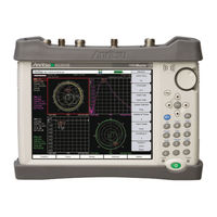
Anritsu MS2026B User Manual (290 pages)
5 kHz to 6 GHz and 5 kHz to 20 GHz Vector Network Analyzers
Brand:
Anritsu
| Category:
Measuring Instruments
| Size: 14.1 MB
Table of Contents
Table of Contents
11
Chapter 1-General Information
21
Introduction
21
Identifying the Connections
21
Description
21
Model Ms202Xb Measurement Capabilities
22
Soft Carrying Case and Tilt Bail
22
VNA Master Soft Carrying Case
22
VNA Master Tilt Bail Stand
24
Preventive Maintenance
25
Calibration Requirements - Vector Network Analyzer
25
Annual Verification
25
ESD Cautions
26
Battery Replacement
26
1-10 Anritsu Service Centers
27
Chapter 2-Quick Start Guide
29
Introduction
29
Turning the VNA Master on for the First Time
29
Front Panel Overview
31
Battery Charge LED (Green)
32
Charge Fault LED (Red)
32
Fan Inlet and Exhaust Ports
33
Typical Vector Network Analyzer Display
34
Instrument Settings Summary
37
Front Panel Keys
38
Esc Key
38
Enter Key
38
Arrow Keys
38
Shift Key
38
Back Key
39
Plus/Minus (+/-) Key
39
Number Keypad
39
Rotary Knob
39
Function Hard Keys
39
Soft Keys
39
Soft Key Types
39
Select
39
Input
40
Toggle
40
Switching
40
Parameter Setting
41
Text Entry
41
Mode Selector
44
2-10 Test Panel Connectors
45
Ms202Xb Test Panel Connectors
45
External Power
46
LAN Connection
47
USB Interface - USB Type Mini-B
48
USB Interface - USB Type a
49
Headset Jack
49
Ext Trigger
49
Ext Freq Ref
49
RF Detector
49
Port 1 (50 Ohm)
50
Port 2 (50 Ohm)
50
Bias Input Port 1
50
Bias Input Port 2
50
Bias Status LED
50
GPS Antenna Connector
50
Symbols and Indicators
51
Battery Symbol
51
Hold
52
Single Sweep
52
2-12 Memory Profile and Security Issues
53
2-13 System Settings
55
Application Options
56
System Options
57
2-14 File Types
59
Chapter 3-VNA Display Overview
61
Introduction
61
Powerful Display Capabilities
61
Flexible Features for Displaying Results
61
Active Trace
62
Changing the Active Trace
62
Trace Description
63
Example Measurement Displays
64
Marker and Limit Capabilities
67
Marker Description
67
Selecting the Readout Style for each Marker
67
Displaying Markers on the Screen
67
Setting up Delta Markers
68
Setting up Limits
68
Trace Math Capabilities
68
Chapter 4-VNA Fundamentals
71
Introduction
71
S-Parameters
71
Additional Examples
72
Ms202Xb VNA Master Architecture
72
Calculating and Displaying S-Parameters
74
Extracting more Information by Using Markers
76
How Bias Is Generated
77
Chapter 5-VNA Measurements
79
Introduction
79
1-Port Cable Measurement
79
Setup Considerations
79
Measurement Readout and Interpretation
79
1-Port Smith Chart Tuning Example
82
2-Port Filter Measurement
84
Introduction
84
Setup Considerations
84
Measurement Readout and Interpretation
84
2-Port Amplifier Measurement
87
Introduction
87
Setup Considerations
87
Measurement Readout and Interpretation
87
Waveguide Considerations
90
Introduction
90
Setup Considerations
90
Measurement Readout and Interpretation
90
Calibration Considerations
91
Cal Type
94
Chapter 6-VNA Menus
95
Introduction
95
VNA Key Functions
95
Frequency Menus
97
Freq Menu
98
Setup Domain Menu
99
Time Menu
100
Windowing Menu
101
Distance Setup Menu
102
Additional Dist Setup Menu (Coax)
103
Additional Dist Setup Menu (Waveguide)
104
Distance Info List Box for Cable
105
Distance Info List Box for Waveguide
105
Calibration Menus
106
Calibration Menu
107
Existing Calibration Information List Box
108
Additional Calibration Considerations
108
DUT Port Setup Menu (Coax)
109
Calibration Menu
109
Cal Kit Definition Menus for Coax
110
DUT Connector Selector List Box for Coax
111
DUT Port Setup Menu (Waveguide)
112
Cal Kit Definition Menus for Waveguide
113
DUT Connector Selector List Box for Waveguide
114
Calibration Types
115
File Menus
116
File Menu
117
Screen Capture Feature
118
Save (Text Entry) Menu
119
File Types
121
Save Location Menu
122
Abbreviated Text Entry Menu
123
Text Entry Letters Menu
124
Recall Menu
125
Delete Menu
126
Copy Menu
128
Limit Menus
130
Limit Menu
131
Limit Edit Menu
132
Marker Menus
133
Marker Menu
134
Marker Search Menu
135
Readout Format Menu
136
Measurement Menus
137
Measure Menu
138
S-Parameter Menu
140
Domain Menu
141
Number of Traces Menu
142
Trace Format Menu
143
Sweep Menu
144
Configure Ports Menu
145
Bias Tee Setup Menu
146
Bias Tee Menu
147
Source Power Menu
147
Preset Menu
148
Scale Menu
149
Smith Scale Menu
150
6-10 System Menus
151
System Menu
152
Application Options
153
System Options
154
Reset Menu
155
Trace Menu
155
Display Menu (Trace)
156
Trace Math Menu
157
Chapter 7 - Time Domain, Option 2
159
Introduction
159
Time Domain Measurements
159
VNA Master Implementation
160
One Way Versus Round Trip
160
Waveguide Dispersion Compensation
162
Windowing
164
Distance-To-Fault Measurement Example
165
In the Measure Menu
165
In the Sweep Menu
165
In the Freq/Time/Dist Menu
165
In the Additional Dist Setup Submenu
165
Time and Distance Information
167
Chapter 8 - Power Monitor, Option 5
171
Introduction
171
Procedure
171
Zeroing the Power Monitor
171
Measuring High Input Power Levels
171
Displaying Power in Dbm or in Watts
172
Setting Relative Power
172
Power Monitor Display
173
Power Monitor Menu
173
Chapter 9 - Secure Data Option 7
175
Introduction
175
Procedure
175
Calibration Setup
176
Memory Profile and Security Issues
177
Chapter 10 - Bias Tee, Option 10
179
10-1 Introduction
179
10-2 Bias Tee Fundamentals
179
10-3 How Bias Is Generated
180
10-4 Bias Tee When Making 2-Port Gain Measurements
182
10-5 Bias Tee Menus
184
Bias Tee Setup Menu
185
Bias Tee Menu
186
Chapter 11-Vector Voltmeter, Option
187
Introduction
187
Getting Started
188
Using Vector Voltmeter Mode for the First Time
189
How the VVM Function Works
189
Simple Measurement Using CW Display
190
Simple Relative Measurements Using CW Display
195
Measurements Using Comparison Table Display
196
Vector Voltmeter Menus
198
CW Menu
198
Save/Recall Menu
200
Calibration Menu
200
Chapter 12-High Accuracy Power Meter, Option
201
12-1 Introduction
201
12-2 High Accuracy Power Meter (HAPM) Display
201
12-3 HAPM General Operating Procedure
202
Turn on the VNA Master and the Sensor
202
Zero/Cal (Calibration) and Cal Factor
203
Change the Analog Scale Display
205
Using Attenuators
205
Displaying Relative Power
206
Averaging/Max Hold/Run Hold
206
Limits
207
Saving the Measurement
208
12-4 Menus
208
12-5 Zero/Cal and Cal Factor Menus
209
12-6 Amplitude and Units Menus
210
12-7 Averages Menu
211
12-8 Limits Menu
212
Chapter 13-GPS Receiver, Option
213
13-1 Introduction
213
13-2 Activating the GPS Feature
213
13-3 GPS Menu
215
13-4 GPS Info Window
216
Tracked Satellites
216
Latitude and Longitude
216
Altitude
216
Utc
216
Fix Available
217
Almanac Complete
217
Antenna Status
217
Receiver Status
217
Other Status Messages
218
GPS Antenna Voltage
218
GPS Antenna Current
218
13-5 Saving and Recalling Traces with GPS Information
218
Saving Traces with GPS Information
218
Recalling GPS Information
218
Chapter 14-Balanced Ports, Option
219
14-1 Introduction
219
14-2 Procedure
219
14-3 Typical Measurements
221
Chapter 15-Anritsu PC Software Tools
225
15-1 Introduction
225
15-2 Anritsu Tool Box
225
15-3 Line Sweep Tools
226
15-4 Master Software Tools
227
15-5 Easymap Tools
228
Appendix A-Signal Standards
229
Introduction
233
Appendix B-Error Messages
233
Reset Options
233
Reset Via Instrument Menus
233
Reset from off Condition
233
Self Test or Application Self Test Error Messages
233
Self Test
233
Application Self Test
235
Operation Error Messages
237
Fan Failure
237
High Temp Warning
237
Operation Not Permitted in Recall Mode
237
PMON PLD Fail
238
Power Supply
238
Appendix C-Windowing
239
Introduction
239
Rectangular Windowing
240
Nominal Side Lobe Windowing
241
Low Side Lobe Windowing
242
Minimum Side Lobe Windowing
243
Appendix D-Tower Mounted Amplifiers
245
Introduction
245
Appendix E-Coaxial Cable Technical Data
247
Appendix F-Waveguide Data
251
Introduction
251
Calibration Components
251
F-4 Flange Compatibility
253
Universal Flange Compatibility
254
F-5 Waveguide Technical Data
257
Appendix G-More about DHCP
261
Introduction
261
Using DHCP
261
Static IP Address
261
IP Address
261
Default Gateway
261
Subnet Mask
261
Example 1
262
Example 2
262
Operating System Tools
262
Ping Tool
262
Appendix H-Formulas
265
VNA Master Formulas
265
Reflection Coefficient
265
Return Loss
265
Vswr
265
Smith Chart
265
Electrical Length
265
Propagation
266
Cable Loss
266
Fault Resolution
266
Maximum Horizontal Distance
266
Suggested Span
267
Index
269
Advertisement
Anritsu MS2026B Manual (256 pages)
Vector Network Analyzer for Anritsu RF and Microwave Handheld Instruments
Brand:
Anritsu
| Category:
Measuring Instruments
| Size: 23.54 MB
Table of Contents
Table of Contents
3
Chapter 1-General Information
11
Introduction
11
Contacting Anritsu
11
VNA Master Models
12
Identifying the Connections
13
Chapter 2-VNA Display Overview
15
Introduction
15
Powerful Display Capabilities
15
Flexible Features for Displaying Results
15
Active Trace
16
Changing the Active Trace
16
Touch Screen Trace Features
17
Trace Description
17
Example Measurement Displays
18
Vector Network Analyzer MG PN: 10580-00289 Rev. K
19
Marker and Limit Capabilities
21
Marker Description
21
Selecting the Readout Style for each Marker
21
Displaying Markers on the Screen
21
Setting up Delta Markers
22
Setting up Limits
22
Markers on a Touch Screen
22
Trace Math Capabilities
23
Chapter 3-VNA Fundamentals
25
Introduction
25
Option 16 (S412E LMR Master)
25
S-Parameters
26
Additional Examples
26
VNA Master Architecture
27
Calculating and Displaying S-Parameters
30
Extracting more Information by Using Markers
32
How Bias Is Generated
32
Chapter 4-VNA Measurements
33
Introduction
33
Select Measurement Type - VNA Versus Field
33
Touch Screen Trace Features
33
Markers on a Touch Screen
33
1-Port Cable Measurement
33
Setup Considerations
33
Measurement Readout and Interpretation
34
1-Port Smith Chart Tuning Example
37
2-Port Filter Measurement
39
Introduction
39
Setup Considerations
39
Measurement Readout and Interpretation
39
2-Port Amplifier Measurement
42
Introduction
42
Setup Considerations
42
Measurement Readout and Interpretation
42
Waveguide Considerations
45
Introduction
45
Setup Considerations
45
Measurement Readout and Interpretation
46
Calibration Considerations
48
Ms20Xxb 1-Path 2-Port Calibration
49
Ms20Xxc Full 2-Port Calibration
50
Calibration Data and Indications
51
Cal Type
52
Chapter 5-Field Measurements
53
Introduction
53
Options
53
Field Measurements View Setting
53
Select Measurement Type - Field Versus VNA
53
Touch Screen Trace Features
53
Markers on a Touch Screen
53
Measurement Setup
54
Setting the Frequency Range
54
Setting the Start and Stop Frequencies
55
Setting Data Points
55
Calibration
55
Graph Type Selector List Box
56
Field Measurements View Versus VNA Measurements View
56
Insertion Loss in Display Type Single
57
VSWR and Return Loss in Display Type Dual
58
Insertion Loss and Return Loss in Display Type Overlay
59
Field View Menus
60
VNA Measurements
60
Return Loss/Vswr
61
Cable Loss
64
Distance-To-Fault (DTF)
66
DTF Measurement Calculations
69
5-10 Phase Measurements
70
1-Port Phase Measurement
70
2-Port Phase Measurement
71
Smith Chart
73
Smith Chart Measurement
73
5-12 Log Mag Display Types
75
Typical Log Magnitude Measurement
75
Dual Channel Filter Tuning Measurement
78
Chapter 6-VNA View Menus
81
Introduction
81
VNA Key Functions
81
Domain Setup Menus
83
Freq Menu
84
Setup Domain Menu
85
Time Menu
86
Time Info List Box
87
Windowing Menu
88
Distance Setup Menu
89
Additional Dist Setup Menu (Coax)
90
Cable List Menu (Coax)
91
Additional Dist Setup Menu (Waveguide)
92
Distance Info List Box for Cable
93
Distance Info List Box for Waveguide
93
FGT Menu
94
Gate Menu
95
Gate Setup Menu (Continued)
96
Gate Shape Menu
97
Calibration Menus
98
Calibration Menu
99
Calibration Menu with Thru
105
Calibration Line Setup Menu
107
Existing Calibration Information List Box
108
Additional Calibration Considerations
108
DUT Port Setup Menu (Coax)
109
Cal Kit Definition Menus for Coax
110
DUT Connector Selector List Box for Coax
111
SOLT - Coax Menu
112
DUT Port Setup Menu (Waveguide)
113
Cal Kit Definition Menus for Waveguide
114
DUT Connector Selector List Box for Waveguide
115
SOLT - WG Menu
116
Calibration Types
117
Limit Menus
118
Limit Menu
119
Limit Edit Menu
120
Marker Menus
121
Marker Menu
122
Marker Search Menu
123
Readout Format Menu
124
Measurement Menus
125
Measure Menu
126
S-Parameter List Box
127
S-Parameter Menu
128
Domain Menu
129
Low Pass Mode Menu
130
Band Pass Mode Menu
130
Number of Traces Menu
131
Trace Format Menu
132
Sweep Menu - Ms20Xxc
133
Sweep Menu - Ms20Xxb and S412E
134
Configure Ports Menu
135
Bias Tee Setup Menu
136
Bias Tee Menu (Ms20Xxc Only)
137
Source Power Menu (Ms20Xxc Only)
138
Source Power Menu (Ms20Xxb and S412E Only)
138
Preset Menu
139
Scale Menu
140
Smith Scale Menu
141
Polar Scale Menu
142
System Menus
143
Application Options Menu (VNA Mode)
144
Application Options Menu (SPA Mode) VNA Master
145
Application Options Menu (SPA Mode) LMR Master
146
Time Domain Options Menu
147
Trace Menu
148
Trace Math Menu
149
Introduction
151
Chapter 7 -Field View Menus
152
Field View Menu Group (Field View)
152
Field View Frequency Menus
153
Freq/Dist Menu (Distance-Based)
154
Distance Menus
155
DTF Setup Menu
156
Cable List Menu
157
Windowing Menu
158
Scale Menus
159
Scale Menu
160
Scale Menu – Dual or Overlay
161
Sweep Menus
162
Sweep Menu
163
Avg/Smooth Menu
164
Measure Menus
165
Measure Menu – Dual
166
Marker Menu
167
Calibration Menu
168
Application Options Menu
169
Introduction
171
Chapter 9 -Distance Domain
172
VNA Master Implementation
172
Time Domain – Impulse Response
175
Step Response Versus Impulse Response
176
Frequency Gated by Time
179
Waveguide with Dispersion Compensation
181
Phasor Impulse
183
Windowing
185
In the Additional Dist Setup Submenu:
186
Time and Distance Information
187
Introduction
189
Chapter 8 -Time Domain, Option 2
190
VNA Master Implementation
190
Windowing
192
Distance Information
194
Introduction
195
How Bias Is Generated
196
Chapter 10 -Bias Tee, Option 10
199
Bias Tee When Making 2-Port Gain Measurements
199
Bias Tee Menus (Ms20Xxc, MS2026B, and MS2028B)
201
Bias Tee Setup Menu
202
Bias Tee Menu
203
Bias Tee Menus (Field Measurements View)
204
Bias Tee Setup Menu
205
Bias Tee Menus (Ms20Xxb and S412E in VNA View)
206
Introduction
207
Chapter 11 -Vector Voltmeter, Option 15
208
Getting Started
208
Using Vector Voltmeter Mode for the First Time
209
How the VVM Function Works
210
Simple Measurement Using CW Display
211
Calibration Correction
212
Relative Measurements Using CW Display
216
Measurements Using Comparison Table Display
218
Vector Voltmeter Menus
220
Table Menu
221
Save/Recall Menu
222
Introduction
223
Chapter 12 -Balanced Ports, Option 77
225
Typical Measurements
225
A-1 Vector Network Analyzer Formulas
229
Appendix A-Formulas
230
Propagation
230
B-1 Introduction
231
Appendix B-Windowing
232
Rectangular Windowing
232
Nominal Side Lobe Windowing
233
Low Side Lobe Windowing
234
Minimum Side Lobe Windowing
235
C-1 Introduction
237
C-3 Self Test or Application Self Test Error Messages
238
Application Self Test Results Window — VNA
240
Application Self Test Results Window — SPA
241
C-4 Operation Error Messages
242
Appendix C-Error Messages
243
PMON PLD Fail
243
Bias Tee State Cannot be Changed During Calibration
244
Limit Is Not Available for this Graph Type
245
Advertisement
Related Products
Anritsu VNA Master MS2024B
Anritsu VNA Master MS2025B
Anritsu MS2024A/MS2026A
Anritsu VNA Master MS2026C
Anritsu VNA Master MS2027C
Anritsu VNA Master MS2028C
Anritsu MS2028B
Anritsu MS2024A
Anritsu MS2026A
Anritsu VNA Master MS202 B Series
Anritsu Categories
Measuring Instruments
Test Equipment
Portable Generator
Control Unit
Thermometer
More Anritsu Manuals
Login
Sign In
OR
Sign in with Facebook
Sign in with Google
Upload manual
Upload from disk
Upload from URL