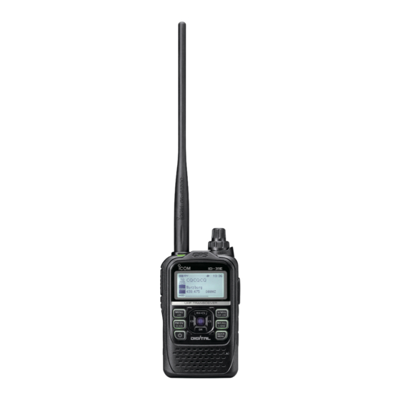
Icom ID-31A Advanced Instructions
Uhf transceiver
Hide thumbs
Also See for ID-31A:
- Instruction manual (80 pages) ,
- Quick manual (2 pages) ,
- Service manual (41 pages)
Table of Contents
Advertisement
ADVANCED INSTRUCTIONS
UHF TRANSCEIVER
ID-31A
ID-31E
INTRODUCTION
1
REPEATER AND DUPLEX OPERATIONS
2
DR MODE <PREPARATION>
3
DR MODE <BASIC>
4
DR MODE <ADVANCED>
5
GPS/GPS-A OPERATION
6
VOICE MEMORY FUNCTION
7
MEMORY CHANNEL PROGRAMMING
8
SCAN OPERATION
9
PRIORITY WATCH
10 MENU SCREEN OPERATION
11 OTHER FUNCTIONS
12 USING A MICROSD CARD
TROUBLESHOOTING
INDEX
Advertisement
Chapters
Table of Contents

Subscribe to Our Youtube Channel
Related Manuals for Icom ID-31A


Summary of Contents for Icom ID-31A
- Page 1 ADVANCED INSTRUCTIONS INTRODUCTION UHF TRANSCEIVER REPEATER AND DUPLEX OPERATIONS ID-31A DR MODE <PREPARATION> ID-31E DR MODE <BASIC> DR MODE <ADVANCED> GPS/GPS-A OPERATION VOICE MEMORY FUNCTION MEMORY CHANNEL PROGRAMMING SCAN OPERATION PRIORITY WATCH 10 MENU SCREEN OPERATION 11 OTHER FUNCTIONS 12 USING A MICROSD CARD...
- Page 2 "SKIP" or "PSKIP," the scan is not started. Icom, Icom Inc. and the Icom logo are registered trademarks of Icom Incorporated (Japan) in Japan, the United States, the United Kingdom, Germany, France, Spain, Russia and/or other countries.
- Page 3 Previous view INTRODUCTION ® ® Functions and features of Adobe Reader The following functions and features can be used with Adobe ® Reader ® • Keyword search Click “Find (Ctrl+F)” or “Advanced Search (Shift+Ctrl+F)” in the Edit menu to open the search screen. This is convenient when searching for a particular word or phrase in this manual.
-
Page 4: Table Of Contents
REPEATER AND DUPLEX OPERATIONS Section FM Repeater operation ..........1-2 ■ Repeater frequency setting ........1-2 Checking the repeater input signal ......1-3 Duplex operation ............1-4 ■ Setting the frequency offset ........1-4 Setting the duplex direction ........1-5 Off band indication ............ -
Page 5: Repeater And Duplex Operations
Previous view REPEATER AND DUPLEX OPERATIONS ■ FM Repeater operation Repeater A repeater receives transmitted signals and retrans- 434.700 MHz 434.700 MHz mits them on a different frequency. The transmit fre- quency is shifted from the receive frequency by a pre- set frequency offset. -
Page 6: D Checking The Repeater Input Signal
Previous view REPEATER AND DUPLEX OPERATIONS D Checking the repeater input signal You can check whether the other station’s transmit sig- nal can be received directly or not, by listening on the repeater input frequency. While monitoring Hold down [SQL] to listen on the repeater input fre- ➥... -
Page 7: Off Band Indication
Previous view REPEATER AND DUPLEX OPERATIONS ■ Duplex operation The Duplex operation shifts the transmit frequency up or down from the receive frequency by an offset amount. D Setting the frequency offset Push [MENU] Push D-pad( ) to select the root item (“DUP/ TONE...”), and then push D-pad(Ent). -
Page 8: D Setting The Duplex Direction
Previous view REPEATER AND DUPLEX OPERATIONS D Setting the duplex direction Push [V/MHz] to select the VFO mode. Push [FM/DV] several times to select the FM mode. Rotate [DIAL] to set the operating frequency. Push Push D-pad( ) to select “DUP,” and then push D- pad(Ent). -
Page 9: Auto Repeater Function
Previous view REPEATER AND DUPLEX OPERATIONS ■ Auto repeater function When the operating frequency falls within the repeater output frequency range, the Auto Repeater function can automatically sets the repeater settings (duplex ON/OFF, duplex direction, tone encoder ON/OFF). The Auto repeater function uses the preset repeater tone frequency and frequency offset. -
Page 10: 1750 Hz Tone
Previous view REPEATER AND DUPLEX OPERATIONS ■ 1750 Hz tone To access most European repeaters, the transceiver must transmit a 1750 Hz tone. For such European re- peaters, perform the following. • This tone can also be used as a ‘Call signal.’ For only the ID-31E: Push [PTT] briefly, then hold down [PTT] to transmit a 1750 Hz tone burst signal. - Page 12 DR MODE <PREPARATION> Section D-STAR ® INTRODUCTION ........... 2-2 ■ About the DR (D-STAR ® Repeater) mode ..... 2-2 ■ Communication Form ............ 2-3 ■ DR mode operation flow chart ........2-4 ■ About Sections 3 and 4 ..........2-4 “MY”...
-
Page 13: Dr Mode
Previous view DR MODE <PREPARATION> ■ D-STAR ® INTRODUCTION • In the original D-STAR ® (Digital Smart Technologies for Amateur Radio) plan, JARL envisioned a system of repeaters grouped together into Zones. • The transceiver can be operated in the digital voice mode, including low-speed data operation, for both transmit and receive. -
Page 14: Communication Form
Previous view DR MODE <PREPARATION> ■ Communication Form In the DR mode, the transceiver has three communica- tion forms as shown below. • Local area call : To call a station through your local area (access) repeater. • Gateway call : To call through your local area (ac- cess) repeater, repeater gateway, and the internet to your destination repeater or individual station’s last... -
Page 15: Dr Mode Operation Flow Chart
Previous view DR MODE <PREPARATION> ■ DR mode operation flow chart To use a repeater gateway, you must register STEP Registering your call sign your call sign with a gateway repeater, usually one near your home location. Ask your nearest repeater’s administrator for details. -
Page 16: My" (Your Own Call Sign) Programming
Previous view DR MODE <PREPARATION> ■ “MY” (Your own call sign) programming Your own call sign must be programmed for both digital voice and low-speed data communications (including GPS transmission). You can store up to 6 “MY” call signs, [MY1]–[MY6]. If necessary, enter a note of up to 4 characters, such as the model of the transceiver, name, area indication, and so on, after your call sign. - Page 18 DR MODE <BASIC> Section Making a Local area call ................3-2 ■ D Making a CQ call through your local area (access) repeater (Local Area CQ) .. 3-2 Making a Gateway call ................. 3-3 ■ Making a CQ call through a gateway repeater (Gateway CQ) ....
-
Page 19: Making A Local Area Call
Previous view DR MODE <BASIC> ■ Making a Local area call To call a station through your local area (access) repeater. Caller: Hamacho430 JM1ZLK repeater * Set the repeater node to ‘B’ for 430 MHz band, Called when you use in other Hamacho area (Tokyo) than Japan. -
Page 20: Making A Gateway Call
Previous view DR MODE <BASIC> ■ Making a Gateway call To call a station through your local area (access) repeater, gateway repeater, the internet and then to your destina- tion repeater. Hirano430 Caller: Hamacho430 repeater repeater JM1ZLK INTERNET Hamacho area (Tokyo) Called Hirano area (Osaka) -
Page 21: One-Touch Reply After Receiving A Call
Previous view DR MODE <BASIC> ■ One-touch reply after receiving a call The calling station’s call sign can be used to quickly and easily reply. Example: Replying to a call from “JM1ZLK.” After receiving a call, the LCD shows the calling sta- tion’s call sign, as shown to the right. -
Page 22: Ur" (Destination Call Sign) Programming Using The Rx History
Previous view DR MODE <BASIC> ■ “UR” (Destination call sign) programming using the RX History A destination call sign must be programmed to a spe- cific individual station or a repeater, for both digital voice and low-speed data communications. Up to 200 call signs can be stored. •... - Page 23 Previous view DR MODE <BASIC> “UR” (Destination call sign) programming (Continued) ■ Push D-pad( ) to select “NAME,” and then push D- pad(Ent). Rotate [DIAL] to select a desired character. (For example: T) • The selected character blinks. [JM1ZLK] is auto- •...
-
Page 24: From" (Access Repeater) Setting
Previous view DR MODE <BASIC> ■ “FROM” (Access repeater) setting Your access repeater must be set to “FROM” when you transmit a call in the DR mode. You have five ways to set the access repeater. Click the title shown below to jump to the specified page. -
Page 25: D From" (Access Repeater) Setting Using The Preloaded Repeater List
Previous view DR MODE <BASIC> “FROM” (Access repeater) setting (Continued) ■ D “FROM” (Access repeater) setting using the preloaded repeater list For easy operation, the repeater list is preloaded into your transceiver. Example: Select the “Hirano430” repeater in Japan from preset repeater list. Hold down for 1 second. -
Page 26: D From" (Access Repeater) Setting Using The Repeater Search Function
Previous view DR MODE <BASIC> D “FROM” (Access repeater) setting using the Repeater Search function The transceiver searches for the nearest repeater by using your own and repeater’s position data. Example: Select the “Hirano430” repeater that is the top search result. 1. - Page 27 Previous view DR MODE <BASIC> “FROM” (Access repeater) setting ■ “FROM” (Access repeater) setting using the Repeater Search function (Continued) 2. Receiving your own position data from the GPS receiver Hold down for 1 second. • The DR mode is selected. Push D-pad( ) to select “FROM,”...
-
Page 28: D From" (Access Repeater) Setting Using The Tx History
Previous view DR MODE <BASIC> D “FROM” (Access repeater) setting using the TX History The TX History stores up to 10 “FROM” (Access re- peater) repeaters used when you transmit a call in the DR mode. NOTE: Only repeaters you transmitted to in the DR mode are stored in the TX History. -
Page 29: D From" (Access Repeater) Setting Using The Dr Mode Scan
Previous view DR MODE <BASIC> “FROM” (Access repeater) setting (Continued) ■ D “FROM” (Access repeater) setting using the DR mode scan The DR mode scan is useful to find a repeater. To quickly find a repeater, the DR mode scan skips repeaters that are not specified as an access repeater. -
Page 30: To" (Destination) Setting
Previous view DR MODE <BASIC> ■ “TO” (Destination) setting The destination repeater or station must be set to “TO” when you transmit a call in the DV mode. You have eight ways to set the destination. Click the title as shown below to jump to the specified page. -
Page 31: D "To" (Destination) Setting Using The "Your Call Sign
Previous view DR MODE <BASIC> “TO” (Destination) setting (Continued) ■ D “TO” (Destination) setting using the “Your Call Sign” The “Your Call Sign” memory stores the programmed “UR” (destination) call sign. When you select an individual station call sign for the “TO”... -
Page 32: D "To" (Destination) Setting Using The Rx History
Previous view DR MODE <BASIC> D “TO” (Destination) setting using the RX History The RX History function stores the name and/or call sign of up to 40 CALLERs, and the only the last CALLED call sign that you received. Even if there was no reply, the CALLED station call sign is also stored, and you can make a call to the CALLED station using RX History. -
Page 33: D To" (Destination) Setting Using The Tx History
Previous view DR MODE <BASIC> “TO” (Destination) setting (Continued) ■ D “TO” (Destination) setting using the TX History The TX History stores the name and/or call sign of up to 20 “TO” (Destination) settings which were used when you made the calls. NOTE: If you never transmit a call in the DV mode, you cannot select “TO”... -
Page 34: D To" (Destination) Setting Using The [Direct Input (Ur)]
Previous view DR MODE <BASIC> D “TO” (Destination) setting using the [Direct Input (UR)] The destination station call sign can be directly input. Example: Directly input the call sign “JM1ZLK.” Hold down for 1 second. • The DR mode is selected. Push D-pad( ) to select “TO,”... -
Page 35: D To" (Destination) Setting Using The [Direct Input (Rpt)]
Previous view DR MODE <BASIC> “TO” (Destination) setting (Continued) ■ D “TO” (Destination) setting using the [Direct Input (RPT)] The destination repeater call sign can be directly in- put. Example: Directly input the call sign “JP3YHH” (Hi- rano430 repeater). Hold down for 1 second. -
Page 36: About "Ur?" And "Rpt?" Error Messages
Previous view DR MODE <BASIC> ■ About “UR?” and “RPT?” error messages The transceiver includes a status message in the signal received back from the access repeater, after transmitting. D Shows “UR?” The call was successfully sent, but no station’s signal was immediately received. -
Page 37: Making A Simplex Call
Previous view DR MODE <BASIC> ■ Making a Simplex call To call a station not using a repeater. Caller: JM1ZLK Called D Making a CQ call through no repeater (Simplex CQ) This section describes how to make a CQ call not through a repeater. -
Page 38: For Your Reference
Previous view DR MODE <BASIC> For your reference ■ Besides the DR mode, you can use the VFO mode, Memory mode or Call channel mode to make DV calls. D Making a Simplex call in the VFO mode Push [V/MHz] to select the VFO mode. - Page 39 Previous view DR MODE <BASIC> For your reference (Continued) ■ D Making a Local Area call or a Gateway call in the VFO mode Besides the DR mode, you can use the VFO mode, Memory mode or Call channel mode to make DV Select calls.
- Page 40 Previous view DR MODE <BASIC> 2. UR call sign setting Select !2 Push D-pad( ) to select “UR,” and then push D- pad(Ent). !3 Push D-pad( ) to select the desired item, and then push D-pad(Ent). • CQCQCQ : Select to make a Local Area CQ call or to a station by saying the station's call sign.
- Page 41 Previous view DR MODE <BASIC> For your reference ■ Making a Local Area call or Gateway call in the VFO mode (Continued) Calling Shows it is a !9 While holding down [PTT], speak into the micro- repeater des- phone at your normal voice level. tination call •...
- Page 42 DR MODE <ADVANCED> Section Message operation ............4-2 ■ TX message programming ........4-2 Message Transmission ..........4-3 TX message deleting ..........4-4 Received call sign confirmation ........4-5 ■ Confirm in the RX History screen ......4-5 BK mode communication ..........
-
Page 43: Dr Mode
Previous view DR MODE <ADVANCED> ■ Message operation The transceiver has a total of 5 message memories to store short messages to transmit during DV mode operation. Messages of up to 20 characters can be programmed in each memory. D TX message programming TX messages of up to 20 characters can be pro- grammed in each of the 5 message memories. -
Page 44: D Message Transmission
Previous view DR MODE <ADVANCED> D Message Transmission You can select a TX message to turn ON the message transmission function. When a TX message is select- ed, and [PTT] is pushed, the transceiver transmits the preprogrammed text message. Push [MENU] Push D-pad( ) to select the root item (“My Station”), ... -
Page 45: Dtx Message Deleting
Previous view DR MODE <ADVANCED> Message operation (Continued) ■ D TX message deleting The programmed TX message can be deleted, as de- scribed below. Example: To delete the programmed TX message “JAPAN >TOM” from message memory number 1. Push [MENU] Push D-pad( ) to select the root item (“My Station”), ... -
Page 46: Received Call Sign Confirmation
Previous view DR MODE <ADVANCED> ■ Received call sign confirmation When a DV call is received, the calling station and the repeater’s call signs are stored in the RX HISTORY screen. Up to 40 calls can be stored. Even if the transceiver is turned OFF, the RX record won’t be deleted. -
Page 47: Bk Mode Communication
Previous view DR MODE <ADVANCED> ■ BK mode communication The BK (Break-in) function allows you to break into a conversation, where the two other stations are commu- nicating with call sign squelch enabled. (Default: OFF) NOTE: The BK function is automatically turned OFF when transceiver is turned OFF. -
Page 48: Emr Communication
Previous view DR MODE <ADVANCED> ■ EMR communication The EMR (Enhanced Monitor Receive) communication mode can be used in only the DV mode. In the EMR mode, no call sign setting is necessary. When an EMR mode signal is received, the audio (voice) will be heard at the specified level, even if the volume setting level is set to the minimum level, or digital call sign/digital code squelch is in use. -
Page 49: D Adjusting The Emr Af Level
Previous view DR MODE <ADVANCED> EMR communication (Continued) ■ D Adjusting the EMR AF level The audio output level when an EMR signal is received is adjustable between 0 and 39. When an EMR signal is received, the audio will be heard at the preset level, or the [VOL] control level, whichever is higher. -
Page 50: Dv Automatic Detection
Previous view DR MODE <ADVANCED> ■ DV automatic detection When an FM Signal is received while in the DV mode, the “DV” and “FM” icons alternately blink. If the DV Auto Detect function is turned ON, the transceiver automati- cally selects the FM mode to temporarily monitor the signal. -
Page 51: Automatic Reply Function
Previous view DR MODE <ADVANCED> ■ Automatic Reply function When a call addressed to your own call sign is re- ceived, the Automatic Reply function automatically re- plies with your call sign. (Default: OFF) Push [MENU] Push D-pad( ) to select the root item (“DV Set”), ... -
Page 52: D Recording A Auto Reply Voice Announcement
Previous view DR MODE <ADVANCED> D Recording a Auto Reply voice announce- ment The Auto Reply voice announcement can be recorded and saved on the microSD card to reply to the call with your voice. NOTE: Be sure to insert a microSD card to the [mi- cro SD] slot of the transceiver before starting to re- cord a voice signal. -
Page 53: Low-Speed Data Communication
: 1 bit • Flow control : Xon/Xoff Depending on the PC environment, the COM port number used by the ID-31A/E may be higher than 5. In such case, use the application which can set to higher than 5. The baud rate can be set in the “Data Speed” item of the MENU screen. -
Page 54: Speech Function
Previous view DR MODE <ADVANCED> ■ Speech function The speech function announces the called station call sign, or the individual or station call sign that is se- lected from the RX History by holding down rotating [DIAL]. (Default: ON (Kerchunk)) It is convenient when you cannot watch the LCD, or you missed the call’s audio. -
Page 55: D To Announce The Rx>Cs Call Sign
Previous view DR MODE <ADVANCED> Speech function (Continued) ■ D To announce the RX>CS call sign The station call sign that is selected from the RX His- tory by holding down and rotating [DIAL], will be announced. (RX>CS Speech function, Default: ON) Push [MENU] Push D-pad( ) to select the root item (“SPEECH”),... -
Page 56: D Speech Language Selection
Previous view DR MODE <ADVANCED> D Speech Language selection The speech language can be set to English or Japa- nese. (Default: English) The selected language is used for both the received call sign speech and the RX>CS call sign speech. Push [MENU] Push D-pad( ) to select the root item (“SPEECH”),... -
Page 57: D Speech Speed Selection
Previous view DR MODE <ADVANCED> Speech function (Continued) ■ D Speech speed selection The speech speed can be set to slow or fast. (Default: Fast) Push [MENU] Push D-pad( ) to select the root item (“SPEECH”), and then push D-pad(Ent). D-pad (Ent) (�) -
Page 58: Digital Squelch Functions
Previous view DR MODE <ADVANCED> ■ Digital squelch functions The digital squelch opens only when receiving a sig- nal addressed to your own call sign, or a signal that includes a matching digital code. You can silently wait for calls from others. D The digital call sign squelch setting Hold down for 1 second. -
Page 59: D The Digital Code Squelch Setting
Previous view DR MODE <ADVANCED> Digital squelch functions (Continued) ■ D The digital code squelch setting Hold down for 1 second. • The DR mode is selected. • To use the digital code squelch function in another mode, push [V/MHz] or [M/CALL] to select the VFO, Memory or CALL channel mode. -
Page 60: Dv Mode Operation In The Memory Mode
Previous view DR MODE <ADVANCED> ■ DV mode operation in the Memory mode You can save the temporary settings in the DR mode to memory. The saved settings can be selected by rotating [DIAL]. D Storing the temporary setting data Example: To register “FROM: Hamacho430”... -
Page 61: Repeater List
CS-31 cloning software About the repeater list: The repeater list can be downloaded from our web- site. http://www.icom.co.jp/world/index.html D Repeater list contents The following contents are included in the repeater Example: “Hamacho430” repeater information list: • NAME (Repeater name) (p. 4-22) •... -
Page 62: New Repeater Programming
Previous view DR MODE <ADVANCED> ■ Repeater list programming Required items for the communication cases This section describes how to manually program new repeater information into the repeater list. Used as Used as a Used for a Repeater list an access destination simplex com- contents... -
Page 63: Dr Mode
Previous view DR MODE <ADVANCED> Repeater list programming (Continued) ■ 2. Repeater name programming u Push D-pad( ) to select “NAME,” and then push D- pad(Ent) to enter the repeater name edit mode. i Rotate [DIAL] to select a desired character. •... - Page 64 Previous view DR MODE <ADVANCED> 4. Repeater call sign programming When used for simplex communication, go to [7. Access repeater setting]. !7 Push D-pad( ) to select “CALL SIGN,” and then push D-pad(Ent) to enter the repeater call sign edit mode.
- Page 65 Previous view DR MODE <ADVANCED> Repeater list programming (Continued) ■ 5. Gateway repeater call sign programming The 8th digit in the call sign, programmed in [4. Re- peater call sign programming] as described above, is automatically set to “G” as the gateway port. And you can skip this setting and go to the next item.
- Page 66 Previous view DR MODE <ADVANCED> 7. Access repeater setting The programmed repeaters can be used as an ac- cess repeater in the DR mode. For simplex operation, or when the programmed repeater is not used as an access repeater, select “NO.”...
-
Page 67: Frequency Offset Programming
Previous view DR MODE <ADVANCED> Repeater list programming (Continued) ■ 9. Duplex direction setting • This item appears only when “YES” is selected in [7. Access repeater setting]. • “DUP–” is automatically set when the access re- peater frequency is programmed in [8. Access re- peater frequency programming]. - Page 68 Previous view DR MODE <ADVANCED> Latitude programming This item appears only when “Approximate” or “Ex- act” is selected in [11. Position data accuracy level setting]. $7 Push D-pad( ) to select “LATITUDE,” and then push D-pad(Ent) to enter the latitude data edit mode. •...
-
Page 69: Editing A Repeater List
Previous view DR MODE <ADVANCED> Repeater list programming (Continued) ■ 15. Storing the repeater list ^2 Push D-pad( ) to select “<<Add Write>>,” and then push D-pad(Ent). Select ^3 Push D-pad( ) to select “YES,” and then push D- ... -
Page 70: Deleting A Repeater List
Previous view DR MODE <ADVANCED> ■ Deleting a repeater list The programmed repeater contents can be deleted from the repeater list. Push [MENU] Push D-pad( ) to select the root item (“DV Memo- ry”), and then push D-pad(Ent). D-pad (Ent) (�) Push D-pad(... -
Page 71: Adding The Repeater Information Using The Rx History
Previous view DR MODE <ADVANCED> ■ Adding the Repeater information using the RX History This section describes how to add a new repeater in- formation to the repeater list using the RX history. Push [MENU] Push D-pad( ) to select the root item (“RX Histo- ... -
Page 72: Rearrange The Display Order Of The Repeater
Previous view DR MODE <ADVANCED> ■ Rearrange the display order of the repeater You can move the programmed repeater in selected lines to rearrange the display order of the repeater in the selected repeater group. The programmed repeater cannot be moved beyond the repeater group. -
Page 73: Skip Setting For The Dr Mode Scan
Previous view DR MODE <ADVANCED> ■ Skip setting for the DR mode scan You can set the unnecessary repeaters to scan skip targets. The selected repeaters are skipped during scanning for faster selection and scanning. You can set the skip setting to all repeaters in the se- lected repeater group, or the individual repeater. -
Page 74: Repeater Group Name Programming
Previous view DR MODE <ADVANCED> ■ Repeater group name programming Push [MENU] Push D-pad( ) to select the root item (“DV Memo- ry”), and then push D-pad(Ent). D-pad (Ent) (�) Push D-pad( ) to select “Repeater List,” and then ... -
Page 75: Repeater Detail Screen
Previous view DR MODE <ADVANCED> ■ Repeater detail screen According to the programmed contents, such as posi- tion data, UTC offset, and so on, the distance between your position and the repeater or repeater time can be displayed on the REPEATER DETAIL screen. Example: Shows the “Hirano430”... -
Page 76: Your (Destination) Call Sign Programming
Previous view DR MODE <ADVANCED> ■ Your (destination) call sign programming A Your (destination) call sign can be manually pro- grammed. The Your (destination) call sign is set to “TO,” you can make a call to a station, even if you don’t know where the station is currently located. - Page 77 Previous view DR MODE <ADVANCED> Destination call sign programming (Continued) ■ !1 Push D-pad( ) to select “CALL SIGN,” and then push D-pad(Ent). !2 Rotate [DIAL] to select the first character. (For example: J) • A to Z, 0 to 9, / and a space can be selected. •...
-
Page 78: Deleting Your (Destination) Call Sign
Previous view DR MODE <ADVANCED> ■ Deleting Your (destination) call sign The Your (destination) call signs can be deleted from the Your Call Sign memory. Push [MENU] Push D-pad( ) to select the root item (“DV Memo- Select the call sign ry”), and then push D-pad(Ent). -
Page 79: Rearrange The Display Order Of Your (Destination) Call Sign
• The selected contents are moved to above the destina- tion. • When “<<Move End>>” is selected, the selected con- tents are moved to the bottom of the YOUR CALL SIGN screen. Blinks Blinks Select the des- tination “ICOM AMC” is moved to the bottom. 4-38... -
Page 80: About The Repeater List Default Values
You can check the repeater list default values using the supplied CS-31 cloning software The ICF (Icom Cloning Format) file, including the de- fault repeater list, can be downloaded from our web- site. Access the following URL to download the ICF file. - Page 82 GPS/GPS-A OPERATION Section GPS operation ............... 5-2 ■ Receiving GPS data ..........5-2 Checking GPS Position ..........5-3 ■ Displaying Position Data ..........5-3 Changing the Grid Locator ......... 5-4 Changing the Compass Direction ......5-5 Saving your own or received position data ....
-
Page 83: Gps/Gps-A Operation
ID-31A/E according to the instructions, shown modes. Also, a NMEA format compatible external GPS below. The cable is not an Icom product and must be receiver can be connected to the ID-31A/E through the made separately. Refer to the wiring diagram for pin [DATA] port. -
Page 84: Checking Gps Position
Previous view GPS/GPS-A OPERATION ■ Checking GPS Position You can check your current position. D Displaying Position Data Push to open the main Quick Menu screen. Push D-pad( ) to select the “GPS position” item, and then push D-pad(Ent). The first MY GPS position screen appears. (1/5) D-pad (Ent) (�) -
Page 85: D Changing The Grid Locator
Previous view GPS/GPS-A OPERATION Checking GPS Position (Continued) ■ D Changing the Grid Locator • The grid locator map of Japan Grid Locator (GL) is a location compressed into a 6 140° character code, calculated by the longitude and the latitude. -
Page 86: D Changing The Compass Direction
Previous view GPS/GPS-A OPERATION D Changing the Compass Direction You can change the compass direction between Head- ing Up, North Up and South Up. Push while the MY Position 1/ RX Position 1/ MEM Position screen is displayed. MY Position 1 Push D-pad( ), then push D-pad(Ent) to display the Compass Direction menu. -
Page 87: D Saving Your Own Or Received Position Data
Previous view GPS/GPS-A OPERATION Checking GPS Position (Continued) ■ D Saving your own or received position data With this function, you can save the position informa- tion of your station from wherever you are, and also the position information of the station you received it from. -
Page 88: Checking Gps Information (Sky View Screen)
Previous view GPS/GPS-A OPERATION ■ Checking GPS Information (Sky view screen) This screen is used to receive GPS satellite when the GPS indicator does not stop blinking for a long time. GPS Information displays the quantity, signal power and position of the GPS satellites. Sky view screen shows the position of GPS satellites. -
Page 89: Adding Or Editing Gps Memory
Previous view GPS/GPS-A OPERATION Adding or editing GPS memory ■ GPS Memory You can add GPS data to GPS Memory. You can add the your own position, other station’s po- sition or any positions that are manually programmed. Also, an alarm can be set to GPS Memory to sound, depending on the distance from your station. - Page 90 Previous view GPS/GPS-A OPERATION GPS Memory name programming y Push D-pad() to select “NAME.” D-pad (Ent) (�) u Push D-pad(Ent), then the editing screen appears. i Rotate [DIAL] to select the first character. • The selected character blinks. • Push D-pad() to move the cursor right or left. •...
- Page 91 Previous view GPS/GPS-A OPERATION GPS memory operation (Continued) ■ GPS Memory date programming !2 Push D-pad() to select “DATE.” D-pad (Ent) (�) !3 Push D-pad(Ent), then the editing date screen ap- pears. • The edited dates are displayed. !4 Rotate [DIAL] to edit the date. •...
- Page 92 Previous view GPS/GPS-A OPERATION GPS Memory longitude programming #0 Push D-pad() to select “LONGITUDE.” D-pad (Ent) (�) #1 Push D-pad(Ent), then the editing screen appears. #2 Rotate [DIAL] to edit the longitude. • The longitude between 0°00.00' to 180°00.00' are programmable.
-
Page 93: Dgps Bank Name Programming
Previous view GPS/GPS-A OPERATION GPS memory operation (Continued) ■ D GPS bank name programming You can program the name of each GPS bank. Push [MENU] Push D-pad( ) to select the root item (GPS), and then push D-pad(Ent). D-pad (Ent) (�) Push D-pad( ) to select “GPS Memory,”... -
Page 94: D Clearing A Gps Data
Previous view GPS/GPS-A OPERATION D Clearing a GPS data GPS memories can be cleared (erased). Please note that erased GPS memories cannot be re- stored. Example: Erasing “My home” Push [MENU] Push D-pad( ) to select the root item (GPS), and then push D-pad(Ent). -
Page 95: Dgps Alarm Setting
Previous view GPS/GPS-A OPERATION GPS memory operation (Continued) ■ D GPS alarm setting A GPS alarm can sound when a target position comes into the alarm area. This function can be set to the caller station, all GPS Memory channels, a specified Memory bank or a specified Memory channel. - Page 96 Previous view GPS/GPS-A OPERATION Example: Alarm Area 2 Setting alarm for all GPS Memories. Push [MENU] Push D-pad( ) to select the root item (GPS), and then push D-pad(Ent). D-pad (Ent) (�) Push D-pad( ) to select “GPS Memory,” and then push D-pad(Ent).
-
Page 97: Transmitting Gps Data
The GSV sentence is incompatible with them. • Those transceivers will not display GPS messages prop- erly if a GSV sentence is sent from the ID-31A/E. • If “Manual” is selected in the GPS select, the GPS sen- tence is artificially selected and transmitted, according to the manually set position data in “Manual Position.”... -
Page 98: Dgps Message Programming
Previous view GPS/GPS-A OPERATION D GPS message programming Enter a GPS message of up to 20 characters to be transmitted with the position data. Example: Adding “OSAKA suzuki” Push [MENU] Push D-pad( ) to select the root item (GPS), and then push D-pad(Ent) to go to the next screen. -
Page 99: Transmitting Gps-A Data
■ Transmitting GPS-A data GPS-A mode is an operating mode supported with the D-PRS to transmit position data. In GPS-A operation, the following codes are transmit- ted to the PC connected to the ID-31A/E. ® GPS-A code is based on APRS code. -
Page 100: D Setting Gps-A
Previous view GPS/GPS-A OPERATION D Setting GPS-A Set to transmit in the GPS-A mode. Setting GPS-A in the GPS TX Mode q Push [MENU] and select “GPS.” w Push D-pad() and D-pad(Ent) to select “GPS TX Mode.” D-pad (Ent) (�) e Push D-pad() and D-pad(Ent) to select “GPS- A(DV-A).”... - Page 101 Previous view GPS/GPS-A OPERATION Transmitting GPS-A data (Continued) ■ Setting Time Stamp Set the time stamp function to transmit the received time data in UTC (Universal Time Coordinated) time. i Push D-pad() and D-pad(Ent) to select “Time Stamp.” D-pad (Ent) (�) o Push D-pad() and D-pad(Ent) to select either the DHM or HMS format.
- Page 102 Previous view GPS/GPS-A OPERATION Setting SSID To assist in identifying a station’s type, the displayed APRS ® based SSID is added after the GPS-A data call sign. The SSID's adding method differs, depending on whether if you enter a space in your call signs or not. !5 Push D-pad() and D-pad(Ent) to select “SSID.”...
- Page 103 Previous view GPS/GPS-A OPERATION Transmitting GPS-A data (Continued) ■ Comment programming Program your comment and transmit it with the GPS-A position data. The number of characters you can enter differs, de- pending on the settings of data extension (p. 5-19) altitude (p.
-
Page 104: D Displaying Your Position Using A Mapping Software
Previous view GPS/GPS-A OPERATION Displaying your position using a map- ping software If you transmit to an I-GATE station, then enter the call sign information on the internet map website, the set GPS-A symbol is displayed. 5-23... -
Page 105: Gps Auto Transmission For Only Simplex
Previous view GPS/GPS-A OPERATION ■ GPS Auto transmission for only Simplex In the DV mode, this function automatically transmits the GPS receiver’s current position data, at a selected interval, and should only be used in Simplex transmission. NOTE: • Your own call sign must be entered to activate the GPS automatic transmission. -
Page 106: Gps Logger Function
1. Insert a microSD card. ( The microSD card is not available from Icom. To use the GPS logger function with the transceiver in the Purchase a card to meet your needs) Sleep mode, the transceiver has an exclusive mode that 2. -
Page 107: D Turning On The Gps Logger Function
Previous view GPS/GPS-A OPERATION GPS Logger function (Continued) ■ D Turning ON the GPS Logger function Turn the GPS logger function ON or OFF, to store your route as you move. When the GPS Logger function is set to ON, the trans- ceiver stores the position data from GPS receiver into microSD card in a specified time interval. -
Page 108: D Viewing The Route On A Pc Map
Previous view GPS/GPS-A OPERATION D Viewing the route on a PC Map If you want to display the your route as you move, copy the log file to your PC. Turn OFF the transceiver, if it’s ON. w Lift OFF the [micro SD] slot cover on the side panel. Push the microSD card in to release, then carefully Slot cover Slot cover... - Page 109 Continued) ■ For your information— About the recorded NMEA sentence for GPS logging Regarding the GPS logging data of the ID-31A/E, each sentence corresponds to the NMEA standard and is recorded in the following format. D GGA sentence (e.g.) $GPGGA,161229.487,3723.2475,N,12158.3416,W,1,07,1.0,9.0,M,25.5,M,3,0000*18<CR><LF>...
-
Page 110: D Using <
<<GPS Logger Only>> outline 1. Insert the microSD card. ( The microSD card is not available from Icom. Pur- chase a card to meet your needs) 2. Turn ON the GPS receiver. 3. Turn ON the GPS Logger function.> Mode - Page 112 A microSD card or a microSDHC card is required if you use the voice memory function. A card is not supplied with this product, therefore purchase a card to fit your needs. When you insert the card into the ID-31A/E, first format it in the ID-31A/E. See Section 12 for details.
-
Page 113: Voice Memory Function
Previous view VOICE MEMORY FUNCTION ■ Recording receive and transmit audio onto the microSD card You can record communication audio onto the mi- NOTE: croSD card. • The DV automatically detecting function the trans- The transceiver records both received and transmitted ceiver records in only the DV mode. -
Page 114: Changing The Recording Mode
Previous view VOICE MEMORY FUNCTION ■ Changing the recording mode The transceiver can record audio only in the “REC Mode” item on the Menu screen. The default setting is “TX&RX” (Both transmit and ➥ receive signals are recorded). Push [MENU] to enter the Menu screen. -
Page 115: Playing Back The Recorded Audio
Previous view VOICE MEMORY FUNCTION ■ Playing back the recorded audio Push [MENU] to enter the Menu screen. Push D-pad( ) to select the root item (Voice Memo), and then push D-pad(Ent) to go to the next level. D-pad (Ent) (�) ( MENU ➪... -
Page 116: Operation While Playing Back
Previous view VOICE MEMORY FUNCTION ■ Operation while playing back You can fast-forward or rewind while playing back. Push to move the previous file. • Push : Fast-forward. D Fast-forward while playing • Push while the playback is pausing Push D-pad(") to fast-forward (default setting: 10 sec- : Pause at the beginning of onds.) the previous file. -
Page 117: Changing The Skip Time
Previous view VOICE MEMORY FUNCTION ■ Changing the skip time You can change the skip time of fast forward and re- wind. Push [MENU] to enter the Menu screen. Push D-pad( ) to select the root item (Voice Memo), and then push D-pad(Ent) to go to the next level. D-pad (Ent) (�) -
Page 118: Voice Player Screen's Explanation
Previous view VOICE MEMORY FUNCTION ■ VOICE PLAYER screen’s explanation The displayed items are follows. q File name The playback file name is displayed. w Recording information The recorded frequency, mode and audio category are displayed. • When the receiving audio is playing back, the audio cat- egory is displayed as “RX.”... -
Page 119: Erasing The Recorded Contents (Audio)
Previous view VOICE MEMORY FUNCTION ■ Erasing the recorded contents (audio) Push [MENU] to enter the Menu screen. Push D-pad( ) to select the root item (Voice Memo), and then push D-pad(Ent) to go to the next level. D-pad (Ent) (�) ( MENU ➪... -
Page 120: Erasing The All Recorded Contents (Audio) In The Folder At A Time
Previous view VOICE MEMORY FUNCTION ■ Erasing the all recorded contents (audio) in the folder at a time Push [MENU] to enter the Menu screen. Push D-pad( ) to select the root item (Voice Memo), and then push D-pad(Ent) to go to the next level. D-pad (Ent) (�) -
Page 121: Erasing The Folder
Previous view VOICE MEMORY FUNCTION ■ Erasing the folder NOTE: All the files in the folder are also erased. Push [MENU] to enter the Menu screen. Push D-pad( ) to select the root item (Voice Memo), and then push D-pad(Ent) to go to the next level. D-pad (Ent) (�) -
Page 122: Erasing The All Folder
Previous view VOICE MEMORY FUNCTION ■ Erasing the all folder NOTE: All the files in the folders are also erased. Push [MENU] to enter the Menu screen. Push D-pad( ) to select the root item (Voice Memo), and then push D-pad(Ent) to go to the next level. D-pad (Ent) (�) -
Page 123: Continue To Record Even If No Signals Receives
Previous view VOICE MEMORY FUNCTION ■ Continue to record even if no signals receives In the default settings, the transceiver records audio only during receiving signals (the squelch opens). If you want to continue recording even if no signal is receiving, do the following steps. -
Page 124: Record The Transmitting And Receiving Audios Into The Same File
Previous view VOICE MEMORY FUNCTION ■ Record the transmitting and receiving audios into the same file The transceiver can record the transmitting and receiv- ing audios to the same file. Push [MENU] to enter the Menu screen. Push D-pad( ) to select the root item (Voice Memo), and then push D-pad(Ent) to go to the next level. -
Page 125: Start To Record When The [Ptt] Switch Is Pushed
Previous view VOICE MEMORY FUNCTION ■ Start to record when the [PTT] switch is pushed The transceiver starts to record the transmitted audio at the same time the [PTT] switch is pushed. After transmitting, the transceiver receives signal in a given amount of time, it also records the received au- dio. -
Page 126: Verifying The File Information
Previous view VOICE MEMORY FUNCTION ■ Verifying the file information The transceiver can display the recorded file’s fre- quency, mode, date, and so on. Push [MENU] to enter the Menu screen. Push D-pad( ) to select the root item (Voice Memo), and then push D-pad(Ent) to go to the next level. -
Page 127: Verifying The Folder Information
Previous view VOICE MEMORY FUNCTION ■ Verifying the folder information The transceiver can display the folder’s name, number of the files in the folder, total capacity of the files and date. Push [MENU] to enter the Menu screen. Push D-pad( ) to select the root item (Voice Memo), and then push D-pad(Ent) to go to the next level. -
Page 128: Verifying The Microsd Card's Free Space And Recordable Time
Previous view VOICE MEMORY FUNCTION ■ Verifying the microSD card’s free space and recordable time Push [MENU] to enter the Menu screen. Push D-pad( ) to select the root item (SD Card), and then push D-pad(Ent). Push D-pad( ) to select “SD Card Info,” and then push D-pad(Ent) to display the SD Card Informa- tion. -
Page 129: Playing Back The Voice Memory Data With The Pc
Previous view VOICE MEMORY FUNCTION ■ Playing back the voice memory data with the PC You can also play back the voice memory data with a However, the recorded information (frequency, date, Double-click the folder in which the file you want to and so on) are not displayed. - Page 130 MEMORY CHANNEL PROGRAMMING Section General description ............7-2 ■ Memory channel contents ......... 7-2 Memory channel selection ..........7-3 ■ Selecting a call channel ..........7-3 ■ Memory channel programming ........7-4 ■ Copying memory and Call channel contents ....7-5 ■...
-
Page 131: Memory Channel Programming
PC. • The microSD card is not available from Icom. Purchase a microSD card to meet your needs. • The CS-31 cloning software that is included on the sup- plied CD can also be used to backup the memory data. -
Page 132: Memory Channel Selection
Previous view MEMORY CHANNEL PROGRAMMING ■ Memory channel selection The Memory mode is used for operation on memory channels, which store programmed frequencies, call signs and other data. Push [M/CALL] once or twice to select the Memory mode. • “MR” blinks when the Memory mode is selected. Appears •... -
Page 133: Memory Channel Programming
Previous view MEMORY CHANNEL PROGRAMMING ■ Memory channel programming [Example]: Programming 430.520 MHz/FM mode into memory channel 11 (a blank channel). Set 430.520MHz in Push [V/MHz] to select the VFO mode. the VFO mode. Set a desired frequency and operating mode: Rotate [DIAL] to set a desired frequency. -
Page 134: Copying Memory And Call Channel Contents
Previous view MEMORY CHANNEL PROGRAMMING ■ Copying memory and Call channel contents This function copies a memory channel’s contents to the VFO, another memory or Call channels. This is useful when searching for signals around a memory channel frequency, and for recalling the frequency off- set, subaudible tone frequency and so on. -
Page 135: D Memory Or Call Channel Another Memory Or Call Channel
Previous view MEMORY CHANNEL PROGRAMMING Copying memory and Call channel contents ■ (Continued) D Memory or Call channelAnother mem- ory or Call channel Select the memory Select the memory or call channel to be copied. channel to be copied. Push [M/CALL] once or twice to select the ➥... -
Page 136: Memory Bank Setting
■ Memory bank setting NOTE: The memory banks are only used to hold The ID-31A/E has a total of 26 banks (A ~ Z). memory channels. Thus if the original memory Regular memory channels 0 to 499 are assigned to channel contents have been changed, the memory any desired bank for easy memory management. -
Page 137: D Directly Programming In To A Memory Bank
Previous view MEMORY CHANNEL PROGRAMMING Memory bank setting ■ (Continued) D Directly programming in to a memory You can also program the memory contents directly into a memory bank channel. This way is a short cut to bank programming the memory channel, and then assigning Example: Programming 432.000 MHz,FM mode into it to a bank. -
Page 138: Memory Bank Selection
Previous view MEMORY CHANNEL PROGRAMMING ■ Memory bank selection Push [M/CALL] once or twice to select the [Example]: Selecting the bank group “A.” Memory mode. Push to open the Quick Menu screen. Push [M/CALL] Push D-pad( ) to select “Bank Select,” and then once or twice to select push D-pad(Ent). -
Page 139: Programming Memory/Bank/Scan Name
Previous view MEMORY CHANNEL PROGRAMMING ■ Programming memory/bank/scan name Each memory channel can be programmed with an alphanumeric channel name for easy recognition. Names can be a maximum of 16 characters. NOTE: Only one name can be programmed for each bank. - Page 140 Previous view MEMORY CHANNEL PROGRAMMING Continued from the previous page Rotate [DIAL] to select a desired character. • Selectable input characters modes are Upper case let- ters, Lower case letters, Numbers or Symbols. Rotate [DIAL] to se- • The selected character blinks. lect “I”.
-
Page 141: Selecting A Memory Name Display
Previous view MEMORY CHANNEL PROGRAMMING ■ Selecting a memory name display While in the memory mode, the programmed memory Push name can be displayed. Push [M/CALL] once or twice to select the Memory mode. Push to open the Quick Menu screen. Push D-pad( ) to select “Display Type,”... -
Page 142: Memory Clearing
Previous view MEMORY CHANNEL PROGRAMMING ■ Memory clearing Contents of programmed memories can be cleared (erased), if desired. Hold down [S.MW] for 1 second to enter the [Example]: Clearing the memory channel 008. Select Memory write mode. • 1 short and 1 long beep sounds. •... - Page 144 SCAN OPERATION Section Scan ................8-2 ■ About the scan function ..........8-2 VFO scan ..............8-2 Memory scan ............. 8-2 Memory bank scan ............ 8-2 Squelch setting for a scan .......... 8-3 Scanning direction ............. 8-3 Tuning step for a VFO scan ........
-
Page 145: Scan
Previous view SCAN OPERATION ■ Scan VFO scan • ALL (Full scan) p. 8-4 Scanning is a versatile function that can automatically Repeatedly scans the entire band. search for signals and makes it easier to locate sta- Band Band tions to contact or listen to, or to skip unwanted chan- edge edge nels or frequencies. -
Page 146: Sql]
Previous view SCAN OPERATION D Squelch setting for a scan The squelch level can be changed to suit your operat- ing style. Set the squelch level to open the squelch, Blinks according to the received signal strength. Blinks The default squelch level is “AUTO.” Squelch level •... -
Page 147: Vfo Scan
Previous view SCAN OPERATION ■ VFO scan There are 5 scan types: full scan, program scan, pro- gram link scan, duplex scan and tone scan. NOTE: The frequencies that are set as skip channels “PSKIP” are skipped during a scan. When the “PROGRAM SKIP”... - Page 148 Previous view SCAN OPERATION VFO mode scan (continued) When a scan name is assigned. When a scan name is assigned, the scan type can be • When the scan name is assigned set by selecting the scan name from the scan type list. (Step r on page 8-4.) NOTE: The scan name is not displayed during a Scan name “SCAN0”...
-
Page 149: Vfo Scan
Previous view SCAN OPERATION ■ Setting and clearing the skip frequencies D Setting the skip frequencies Example: Full-scanning in the FM mode. The frequencies set as skip channels “PSKIP” are skipped (not scanned). Blinks Start the VFO scan (p. 8-4). Blinks •... -
Page 150: Memory Scan
Previous view SCAN OPERATION ■ Memory scan There two types of scan in the memory mode: Memory scan and memory bank scan. • Channels set as “PSKIP” or “SKIP” is skipped during Hold down [SCAN] a scan. for 1 second. •... -
Page 151: D Memory Bank Scan
Previous view SCAN OPERATION D Memory bank scan A memory bank scan searches through the memory channels in the selected bank. Hold down [SCAN] • Two or more memory channels, which are not set 1 second. as skip channels, must be programmed into start a memory bank scan. - Page 152 Previous view SCAN OPERATION Memory bank scan (continued) When a bank name is programmed • When the bank name is programmed. When a bank name is programmed, the scan type can be set by selecting the bank name from the scan type Bank name “UHF CONTEST”...
-
Page 153: Setting And Clearing Skip Channel
Previous view SCAN OPERATION ■ Setting and clearing skip Example: Set “SKIP” to bank channel “Z98.” channel Rotate [DIAL] to select the memory channel. The channels set as “SKIP” skip channels are skipped (not scanned). Push [M/CALL] to select the memory mode. Push Rotate [DIAL] to select the memory channel to be set as a skip channel. - Page 154 PRIORITY WATCH Section PRIORITY WATCH ............9-2 ■ VFO frequency and a memory channel ..... 9-2 VFO frequency and a bank channel ......9-2 VFO frequency and a Call channel ......9-2 VFO scan and a memory channel ......9-2 VFO scan and a bank channel ........
-
Page 155: Priority Watch
Previous view PRIORITY WATCH ■ PRIORITY WATCH While operating on a VFO frequency, DR mode or while scanning, Priority watch checks for signals on a selected fre- quency every 5 seconds. VFO frequency and a memory channel VFO scan and a memory scan Checks the selected memory Sequentially checks the mem- channel every 5 seconds, while... - Page 156 Previous view PRIORITY WATCH ■ VFO FREQUENCY AND A MEMORY CHANNEL Checks for signals on the selected memory channel every 5 seconds, while receiving on a VFO frequency. Example: Checks memory channel “490” every 5 sec- onds, while receiving on 435.200 MHz. Push [V/MHz] to select the VFO mode.
- Page 157 Previous view PRIORITY WATCH VFO FREQUENCY AND A MEMORY CHANNEL (Continued) ■ When a signal is received. • When “ON” is selected. Blinks When a signal is received on the priority channel, the memory mode is automatically selected. The “PRIO” icon blinks on the screen. * The scan pause timer and resume settings are the same as for a normal scan.
-
Page 158: Vfo Frequency And Bank Channel
Previous view PRIORITY WATCH ■ VFO FREQUENCY AND BANK CHANNEL Checks the selected bank channel (priority channel), Example: Checks bank channel “Z98” every 5 seconds, while receiving on a VFO frequency. while receiving on 433.000 MHz. Push [M/CALL] Push [V/MHz] to select the VFO mode. - Page 159 Previous view PRIORITY WATCH VFO FREQUENCY AND BANK CHANNEL (Continued) ■ When a signal is received. • When “ON” is selected. Blinks When a signal is received on the priority channel, the memory bank mode is automatically selected. The “PRIO” icon blinks on the screen. * The scan pause timer and resume settings are the Automatically changes to the memory bank mode.
-
Page 160: Vfo Frequency And Call Channel
Previous view PRIORITY WATCH ■ VFO FREQUENCY AND CALL CHANNEL Checks the selected Call channel (priority channel), while receiving on a VFO frequency. Example: Checks Call channel “C0” every 5 seconds, Push [V/MHz] to select the VFO mode. while receiving on 431.860 MHz. Rotate [DIAL] to set the receive frequency. - Page 161 Previous view PRIORITY WATCH VFO FREQUENCY AND CALL CHANNEL (Continued) ■ When a signal is received. • When “ON” is selected. Blinks When a signal is received on the priority channel, the Call channel mode is automatically selected. The “PRIO” icon blinks. * The scan pause timer and resume settings are the same as for a normal scan.
-
Page 162: Vfo Scan And Memory Channel
Previous view PRIORITY WATCH ■ VFO SCAN AND MEMORY CHANNEL Checks the selected memory channel (priority chan- nel), during a VFO scan. Example: Checks memory channel “490” every 5 sec- Push [M/CALL] to select the memory mode. onds, during a VFO scan. Rotate [DIAL] to select the channel you want to watch. - Page 163 Previous view PRIORITY WATCH VFO SCAN AND MEMORY CHANNEL (Continued) ■ When a signal is received. • When “ON” is selected. Blinks When a signal is received on the priority channel, the memory mode is automatically selected. The “PRIO” icon blinks. * The scan pause timer and resume settings are the same as for a normal scan.
-
Page 164: Vfo Scan And Bank Channel
Previous view PRIORITY WATCH ■ VFO SCAN AND BANK CHANNEL Example: Checks bank channel “Z98” every 5 seconds, during a VFO scan. Checks the selected bank channel (priority channel), Push during a VFO scan. Push [M/CALL] to select the memory mode. Push Push D-pad( ) to select “Bank Select,”... - Page 165 Previous view PRIORITY WATCH VFO SCAN AND BANK CHANNEL (Continued) ■ When a signal is received. • When “ON” is selected. When a signal is received on the priority channel, Blinks the memory bank mode is automatically selected. The “PRIO” icon blinks. * The scan pause timer and resume settings are the same as for a normal scan.
-
Page 166: Vfo Scan And Call Channel
Previous view PRIORITY WATCH ■ VFO SCAN AND CALL CHANNEL Example: Checks Call channel “C0” every 5 seconds, Checks the selected Call channel (priority channel), during a VFO scan. during a VFO scan. Push [M/CALL] to select the Call channel mode. - Page 167 Previous view PRIORITY WATCH VFO SCAN AND CALL CHANNEL (Continued) ■ When a signal is received. • When “ON” is selected. Blinks When a signal is received on the priority channel, the Call channel mode is automatically selected. The “PRIO” icon blinks. * The scan pause timer and resume settings are the same as for a normal scan.
-
Page 168: Vfo Frequency And Memory Scan
Previous view PRIORITY WATCH ■ VFO FREQUENCY AND MEMORY SCAN Example: Sequentially checks the memory channels Checks the memory channels (priority channel) every every 5 seconds, while receiving on 432.380 5 seconds, in sequence, while receiving on a VFO fre- MHz. - Page 169 Previous view PRIORITY WATCH VFO FREQUENCY AND MEMORY SCAN (Continued) ■ When a signal is received. • When “ON” is selected. Blinks When a signal is received on the priority channel, the memory mode is automatically selected. The “PRIO” icon blinks. * The scan pause timer and resume settings are the same as for a normal scan.
-
Page 170: Vfo Frequency And Bank Scan
Previous view PRIORITY WATCH ■ VFO FREQUENCY AND BANK SCAN Example: Sequentially checks the memory channels in bank “Z” every 5 seconds, while receiving Checks the bank channels (priority channel) every 432.380 MHz. 5 seconds, in sequence, while receiving on a VFO fre- Push [M/CALL] quency. - Page 171 Previous view PRIORITY WATCH VFO FREQUENCY AND BANK SCAN (Continued) ■ When a signal is received. • When “ON” is selected. When a signal is received on the priority channel, Blinks the memory bank mode is automatically selected. The “PRIO” icon blinks. * The scan pause timer and resume settings are the same as for a normal scan.
-
Page 172: Vfo Scan And Memory Scan
Previous view PRIORITY WATCH ■ VFO SCAN AND MEMORY SCAN Example: Checks the memory channels every 5 sec- onds, in sequence, during a VFO scan. Checks the memory channels (priority channel) every Hold down [SCAN] 5 seconds, in sequence, during a VFO scan. for 1 second. - Page 173 Previous view PRIORITY WATCH VFO SCAN AND MEMORY SCAN (Continued) ■ When a signal is received. • When “ON” is selected. Blinks When a signal is received on the priority channel, the memory mode is automatically selected. The “PRIO” icon blinks. * The scan pause timer and resume settings are the same as for a normal scan.
-
Page 174: Vfo Scan And Bank Scan
Previous view PRIORITY WATCH ■ VFO SCAN AND BANK SCAN Example: Checks the bank channels every 5 seconds, in sequence, during the VFO scan. Checks the bank channels (priority channel) every 5 Push seconds, in sequence, during a VFO scan. Push [M/CALL] to select the memory mode. - Page 175 Previous view PRIORITY WATCH VFO SCAN AND BANK SCAN (Continued) ■ Appears Appears Blinks Blinks Checks the bank chan- During the VFO scan. nel every 5 seconds. When a signal is received. • When “ON” is selected. Blinks When a signal is received on the priority channel, the memory bank mode is automatically selected.
- Page 176 Previous view PRIORITY WATCH ■ DR MODE AND VFO FREQUENCY Example: Checks “432.380 MHz” every 5 seconds, while receiving on the repeater in the DR Checks the VFO frequency (priority channel) every 5 mode. seconds, while receiving a repeater in the DR mode. Hold down [DR] for 1 sec- ond.
- Page 177 Previous view PRIORITY WATCH DR MODE AND VFO FREQUENCY (Continued) ■ When a signal is received. • When “ON” is selected. Blinks When a signal is received on the priority channel, the VFO mode is automatically selected. The “PRIO” icon blinks. * The scan pause timer and resume settings are the same as for a normal scan.
-
Page 178: Dr Mode Scan And Vfo Frequency
Previous view PRIORITY WATCH ■ DR MODE SCAN AND VFO FREQUENCY Example: Checks “432.380 MHz” every 5 seconds, Checks the VFO frequency (priority channel) every during the DR mode scan 5 seconds, during a DR mode scan. Hold down [DR] for 1 sec- ond. - Page 179 Previous view PRIORITY WATCH DR MODE SCAN AND VFO FREQUENCY (Continued) ■ When a signal is received. • When “ON” is selected. Blinks When a signal is received on the priority channel, the VFO mode is automatically selected. The “PRIO” icon blinks.
-
Page 180: Dr Mode And Call Channel
Previous view PRIORITY WATCH ■ DR MODE AND CALL CHANNEL Checks the Call channel (priority channel) every 5 sec- onds, while receiving a repeater in the DR mode. Example: Checks Call channel “C0” every 5 sec- onds, while receiving the repeater in the DR mode. - Page 181 Previous view PRIORITY WATCH DR MODE AND CALL CHANNEL (Continued) ■ When a signal is received. • When “ON” is selected. Blinks When a signal is received on the priority channel, the Call channel mode is automatically selected. The “PRIO” icon blinks. * The scan pause timer and resume settings are the same as for a normal scan.
-
Page 182: Dr Mode Scan And Call Channel
Previous view PRIORITY WATCH ■ DR MODE SCAN AND CALL CHANNEL Checks the Call channel (priority channel) every 5 sec- Example: Checks Call channel “CO” every 5 seconds, onds, during a DR mode scan. during the DR mode scan. Hold down [DR] for 1 sec- ond. - Page 183 Previous view PRIORITY WATCH DR MODE SCAN AND CALL CHANNEL (Continued) ■ When a signal is received. • When “ON” is selected. Blinks When a signal is received on the priority channel, the Call channel mode is automatically selected. The “PRIO” icon blinks. Push [CLR] to resume the priority scan.
-
Page 184: Dr Mode And Memory Channel
Previous view PRIORITY WATCH ■ DR MODE AND MEMORY CHANNEL Checks the memory channel (priority channel) ev- Example: Checks memory channel “490” every 5 sec- ery 5 seconds, while receiving a repeater in the DR onds, while receiving the repeater in the DR mode. - Page 185 Previous view PRIORITY WATCH DR MODE AND MEMORY CHANNEL (Continued) ■ When a signal is received. • When “ON” is selected. Blinks When a signal is received on the priority channel, the memory mode is automatically selected. The “PRIO” icon blinks. * The scan pause timer and resume settings are the same as for a normal scan.
-
Page 186: Dr Mode Scan And Memory Channel
Previous view PRIORITY WATCH ■ DR MODE SCAN AND MEMORY CHANNEL Example: Checks memory channel “490” every 5 sec- Checks the memory channel (priority channel) every 5 onds, during the DR mode scan. seconds, during a DR mode scan. Hold down [DR] for 1 sec- ond. - Page 187 Previous view PRIORITY WATCH DR MODE SCAN AND MEMORY CHANNEL (Continued) ■ When a signal is received. • When “ON” is selected. Blinks When a signal is received on the priority channel, the memory mode is automatically selected. The “PRIO” icon blinks. Push [CLR] to resume the priority scan.
- Page 188 MENU SCREEN OPERATION Section Menu items and Default settings ......... 10-2 ■ DUP/TONE items ............10-12 ■ Scan items ..............10-14 ■ Voice Memo items ............. 10-18 ■ GPS items ..............10-22 ■ Call sign items ............10-38 ■ RX History items ............
-
Page 189: Menu Screen Operation
Previous view MENU SCREEN OPERATION ■ Menu items and Default settings NOTE: The default settings, shown below, are for the USA version. The default settings may differ, depending on the version. DUP/TONE... In this item, set the repeater options, for example duplex offset or the channel tone types. RANGE OR VALUE (Default is shown in bold) DESCRIPTIONS Sets the frequency offset for duplex... - Page 190 Previous view MENU SCREEN OPERATION NOTE: The default settings, shown below, are for the USA version. The default settings may differ, depending on the version. Scan In this item, set the scan options. RANGE OR VALUE (Default is shown in bold) DESCRIPTIONS Selects the scan pause time.
- Page 191 Previous view MENU SCREEN OPERATION Menu items and Default settings (Continued) ■ NOTE: The default settings, shown below, are for the USA version. The default settings may differ, depending on the version. In this item, set the GPS options. DESCRIPTIONS RANGE OR VALUE (Default is shown in bold) Selects a GPS receiver that the trans- GPS Set...
- Page 192 Previous view MENU SCREEN OPERATION NOTE: The default settings, shown below, are for the USA version. The default settings may differ, depending on the version. GPS (Continued) In this item, set the GPS options. GPS TX Mode RANGE OR VALUE (Default is shown in bold) DESCRIPTIONS Enters an unproto Address.
- Page 193 Previous view MENU SCREEN OPERATION Menu items and Default settings (Continued) ■ NOTE: The default settings, shown below, are for the USA version. The default settings may differ, depending on the version. In this item, set and display the call signs used in the DV mode. Call Sign DESCRIPTIONS Displays the operating call signs.
- Page 194 Previous view MENU SCREEN OPERATION NOTE: The default settings, shown below, are for the USA version. The default settings may differ, depending on the version. DV Set infrequently changed values or functions in the DV mode. In this item, set DESCRIPTIONS RANGE OR VALUE (Default is shown in bold) Sets the DV mode received audio bass filter...
- Page 195 Previous view MENU SCREEN OPERATION Menu items and Default settings (Continued) ■ NOTE: The default settings, shown below, are for the USA version. The default settings may differ, depending on the version. the Speech functions. SPEECH In this item, set DESCRIPTIONS RANGE OR VALUE (Default is shown in bold) Selects the RX call sign speech function op-...
- Page 196 Previous view MENU SCREEN OPERATION NOTE: The default settings, shown below, are for the USA version. The default settings may differ, depending on the version. Function In this item, set other options DESCRIPTIONS RANGE OR VALUE (Default is shown in bold) Selects the Power Save options to Power Save OFF, Auto (Short), Auto (Middle) or Auto...
- Page 197 Previous view MENU SCREEN OPERATION Menu items and Default settings (Continued) ■ NOTE: The default settings, shown below, are for the USA version. The default settings may differ, depending on the version. Function (Continued) In this item, set other options DESCRIPTIONS RANGE OR VALUE (Default is shown in bold) Sets the transceiver's unique CI-V hexa-...
- Page 198 Previous view MENU SCREEN OPERATION NOTE: The default settings, shown below, are for the USA version. The default settings may differ, depending on the version. Sounds In this item, set the Sound options RANGE OR VALUE (Default is shown in bold) DESCRIPTIONS Sets the beep output level.
-
Page 199: Offset Frequency
Previous view MENU SCREEN OPERATION ■ DUP/TONE items Offset frequency (Default: 5.000.00*) DUP/TONE... > Offset Freq(OFFSET FREQ) Sets the offset frequency for duplex (repeater) operation to between 0 and 59.99500 MHz. • The selected tuning step in the VFO mode is used when setting the offset frequency. -
Page 200: Tone Burst
Previous view MENU SCREEN OPERATION Tone Burst (Default: OFF) DUP/TONE... > Tone Burst(TONE BURST) Turn the Tone Burst function for the FM mode ON or OFF. • OFF : When you transmit a signal that superimposes the CTCSS tone or subaudible tone, a short burst of noise may be heard on the from the receiver, just after you stop transmitting. -
Page 201: Scan Items
Previous view MENU SCREEN OPERATION ■ Scan items Pause Timer (Default: 10sec) Scan > Pause Timer(PAUSE TIMER) Selects the scan Pause time. When receiving a signal, the scan pauses according to the scan Pause timer. • 2–20sec : When a signal is received, the scan pauses for 2 to 20 seconds (set in 2 seconds steps). -
Page 202: Bank Link
Previous view MENU SCREEN OPERATION Bank Link (Default: A: ✔ – Z: ✔ ) Scan > Bank Link(BANK LINK) Select banks to be scanned during a Bank Link Scan. The Bank Link function provides a continuous Bank Scan, which scans all channels in the selected banks. - Page 203 Previous view MENU SCREEN OPERATION Scan items (Continued) ■ Program Link (Default: Refer to the diagram below) Scan > Program Link(PROGRAM LINK) The Program Scan Link sets the link function for program scans pro- grammed in the program scan edge channels. The selected programmed scan number also shows the frequency range.
- Page 204 Previous view MENU SCREEN OPERATION Program scan link name programming q Push D-pad() to select a program scan link number between 0 and 9. D-pad (Ent) (�) w Push e Push D-pad(Ent) to enter the name edit mode. r Rotate [DIAL] to select the first character of the name you wish to pro- gram.
-
Page 205: Voice Memo Items
Previous view MENU SCREEN OPERATION ■ Voice Memo items <<REC Start>> Voice Memo > QSO Recorder > <<REC Start>> Push D-pad() to select “<<REC Start>>,” and then push D-pad(Ent). “Recording started. ”appears and voice recording starts. • “<<REC Stop>>” item is displayed while recording. Be sure to insert a microSD card into the transceiver before selecting •... - Page 206 Previous view MENU SCREEN OPERATION NOTE: • The folder name is automatically created, as shown in the example below; Recording date : 2011/9/1 Folder name : 20110901 • The file name is automatically created, as shown in the example be- low;...
-
Page 207: File Split
Previous view MENU SCREEN OPERATION Voice Memo items (Continued) ■ File Split (Default: ON) Voice Memo > QSO Recorder > Recorder Set > File Split(FILE SPLIT) Turn the File Split function ON or OFF. • OFF : When the recording starts, a new file is automatically created in the folder of the microSD card. -
Page 208: Dv Auto Reply
Previous view MENU SCREEN OPERATION DV Auto Reply Voice Memo > DV Auto Reply(DV AUTO REPLY) Up to 10 seconds of audio can be recorded for the automatic reply function (p. 4-10). Be sure to insert a microSD card into the transceiver before selecting this item. -
Page 209: Gps Items
Previous view MENU SCREEN OPERATION ■ GPS items GPS Select (Default: OFF) GPS > GPS Set > GPS Select(GPS SELECT) Select either an internal or external GPS receiver that the transceiver re- ceives its position data from. • OFF : A GPS receiver is not used. •... -
Page 210: Gps Indicator
Previous view MENU SCREEN OPERATION Manual Position (Default: LATITUDE : 0°00’00”N LONGITUDE : 0°00’00”E ALTITUDE : ------m) GPS > GPS Set > Manual Position(MANUAL POSITION) Manually enter the latitude, longitude and Altitude of your current position. The received position data can be captured by selecting “Capture From GPS” when position data is received from either the internal or an external GPS. -
Page 211: Alarm Area
Previous view MENU SCREEN OPERATION GPS items (Continued) ■ Alarm Area1 (Default: 0.25') GPS > GPS Set > Alarm Area1(ALARM AREA1) When the GPS Alarm function is set to “ALL” or one of the memory banks, set the GPS alarm active range. The programmable values depend on the setting in Position Format. - Page 212 Previous view MENU SCREEN OPERATION Alarm Area2 (Default: Both) GPS > GPS Set > Alarm Area2(ALARM AREA2) Select the GPS alarm active range. When the GPS Alarm function is set in a memory channel or “RX,” set the GPS alarm active range to “Both,” “Extended” or “Limited”. •...
-
Page 213: Gps Information
Previous view MENU SCREEN OPERATION GPS items (Continued) ■ GPS Information GPS > GPS Information(GPS INFO) Displays the GPS satellite direction, elevation, satellite number and receiv- ing status. NOTE: The default settings, shown below, are for the USA version. The default settings may differ, depending on the version. Example: tracking 4 satellites Non tracking satellites ... -
Page 214: Gps Position
Previous view MENU SCREEN OPERATION GPS Position GPS > GPS Position(GPS POSITION) Your current position, received position or GPS memory alarm position information is displayed. (p. 5-3) Push D-pad( ) to select the screen to see the “MY,” “RX” and “MEM” ... -
Page 215: Gps Memory
Previous view MENU SCREEN OPERATION GPS items (Continued) ■ GPS Memory GPS > GPS Memory(GPS MEMORY) The transceiver has 100 GPS memory channels to store the received posi- tion data, or often-used position data, along with an alphanumeric channel name. The display of the GPS memory The last position data received from any station is stored in a temporary memory. - Page 216 Previous view MENU SCREEN OPERATION GPS Logger (Default: OFF) GPS > GPS Logger > GPS Logger(GPS LOGGER) Turn the GPS Logger function ON or OFF. This function logs the position, altitude, course, speed and number of satel- lites being used. •...
-
Page 217: Gps Tx Mode
• GPS-A (DV-A) : Transmits position data in the format corresponding to D- PRS. (the TX GPS mode is “GPS-A”) In the GPS-A mode, the normal GPS-A codes are trans- mitted to the PC connected to the ID-31A/E. GPS-A code is based on APRS ®... - Page 218 (IC-2820H, IC-E2820, ID-800H, IC-91AD, IC-E91, IC-V82, IC-U82, IC-2200H, ID-1). The GSV sentence is incompatible with them. Those transceivers will not display GPS messages properly if sent as a GSV sentence from the ID-31A/E. • Contents of GPS sentence Date Sentence...
-
Page 219: Gps Message
Previous view MENU SCREEN OPERATION GPS items (Continued) ■ GPS Message GPS > GPS TX Mode > GPS(DV-G) > GPS Message(GPS MESSAGE) Enter a GPS message of up to 20 alphanumeric characters. (p. 5-17) GPS Message edit screen This GPS Message item will be hidden when “GPS-A(DV-A)” or “OFF” is selected in “GPS TX Mode.”... - Page 220 Previous view MENU SCREEN OPERATION Data Extension (Default: OFF) GPS > GPS TX Mode > GPS-A(DV-A) > Data Extension(DATA EXTEN- SION) Select whether or not to transmit the course and speed data in addition to the position data. • OFF : Transmits only the position data.
- Page 221 Previous view MENU SCREEN OPERATION GPS items (Continued) ■ GPS-A Symbol (Default: Person) GPS > GPS TX Mode > GPS-A(DV-A) > GPS-A Symbol(GPS-A SYM- BOL) The GPS-A symbol is an icon which represents your means of transporta- tion or location. The stored GPS-A symbol in the selected GPS-A channel (1 to 4) is trans- mitted with position data while in the GPS-A mode.
- Page 222 Previous view MENU SCREEN OPERATION Selecting a pre-programmed GPS-A symbol Push D-pad( ) to select a desired GPS-A Symbol channel between 1 and 4. D-pad (Ent) (�) Push to select “Edit Symbol,” and then push D-pad(Ent). Push D-pad( ) to select a desired GPS- ...
- Page 223 Previous view MENU SCREEN OPERATION GPS items (Continued) ■ SSID (Default: ---) GPS > GPS TX Mode > GPS-A(DV-A) > SSID(SSID) Select an SSID based on APRS ® to add to your call sign, to show your operating style to other stations. The addition methods of the SSID may differ, depending on whether the call sign includes a space or not.
- Page 224 Previous view MENU SCREEN OPERATION Comment GPS > GPS TX Mode > GPS-A(DV-A) > Comment(COMMENT) Enter a comment of up to 43 characters to transmit with the position data. Comment edit screen (In case of up to 43 characters) The number of characters to enter will differ, depending on the Data Extension and Altitude settings.
-
Page 225: Call Sign
Previous view MENU SCREEN OPERATION ■ Call sign items Call Sign Call Sign(CALL SIGN) Sets or displays the “UR,” “R1,” “R2” and “MY” call signs to be used for DV operation. Except for the DR mode, sets the desired call signs to be used for DV op- eration in this screen. - Page 226 Previous view MENU SCREEN OPERATION 2. Gateway (“R2”) setting Push D-pad( ) to select “R2,” and then push D-pad(Ent). Push D-pad( ) to select “GW,” and then push D-pad(Ent). • When you manually enter the call sign, push in step q.
-
Page 227: Rx History Items
Previous view MENU SCREEN OPERATION ■ RX History items RX History RX History(RX HISTORY) When a call is received in the DV mode, the call information such as the caller station call sign, used repeater call sign, and so on, are stored in this screen. - Page 228 Previous view MENU SCREEN OPERATION Contents of the RX history Shows the call sign of the caller station and any note pro- CALLER* grammed after the call sign. CALLED* Shows the call sign of the called station. Shows the call sign of the repeater that was accessed by the caller station.
-
Page 229: Dv Memory Items
We recommend that memory data be backed up externally, or be saved to a PC using the supplied CS-31 cloning software. About the repeater list: The repeater list can be downloaded from the Icom website. http://www.icom.co.jp/world/index.html 10-42... -
Page 230: Group Use(From) Frequency Dup
Previous view MENU SCREEN OPERATION Repeater Group (01 to 20) Repeater group name of up to 16 alphanumeric charac- Group name ters The Skip setting can be turned ON or OFF in the QUICK MENU screen. Repeater List NAME Repeater name of up to 16 alphanumeric characters SUB NAME Repeater sub name of up to 8 alphanumeric characters CALL SIGN... -
Page 231: My Station Items
Previous view MENU SCREEN OPERATION ■ My Station items My Call Sign My Station > My Call Sign(MY CALL SIGN) The transceiver has a total of 6 memories to store your own call signs. A call sign of up to 8 digits can be entered. Also, a note of up to 4 characters, for operating radio type, area, and so on, can be entered. -
Page 232: Dv Set Items
Previous view MENU SCREEN OPERATION ■ DV Set items RX Bass (Default: Normal) DV Set > Tone Control > RX Bass(RX BASS) Set the DV mode received audio bass filter level to Cut, Normal or Boost. • Cut : Cuts the bass tone •... - Page 233 Previous view MENU SCREEN OPERATION DV Set items (Continued) ■ Auto Reply (Default: OFF) DV Set > Auto Reply(AUTO REPLY) Set the automatic reply function to ON, OFF or Voice. This function automatically replies to a call addressed to your own call sign, even if you are away from the transceiver.
-
Page 234: Rx Call Sign Write
Previous view MENU SCREEN OPERATION RX Call Sign Write (Default: OFF) DV Set > RX Call Sign Write(RX CALL SIGN WRITE) Set the RX call sign automatic write function to Auto or OFF. When receiving a call addressed to your own call sign in a mode other than the DR mode, this function automatically sets the call sign of the caller sta- tion into “UR.”... - Page 235 Previous view MENU SCREEN OPERATION DV Set items (Continued) ■ (Default: OFF) DV Set > BK(BK) The BK (Break-in) function allows you to break into a conversation, where the two other stations are communicating with call sign squelch enabled. • OFF : Turns the function OFF. •...
-
Page 236: Speech Items
Previous view MENU SCREEN OPERATION ■ SPEECH items RX Call Sign SPEECH (Default: ON (Kerchunk)) SPEECH > RX Call Sign SPEECH(RX CALL SIGN SPEECH) Turn the RX call sign speech function ON or OFF. • OFF : No announcement is made even when a call is received. •... -
Page 237: Dtmf Memory
Previous view MENU SCREEN OPERATION ■ DTMF/T-CALL items Programs and sets the DTMF tone code and DTMF memory channel for DTMF tone operation. See pages 11-2 through 11-6 for details. DTMF Memory (Default: d0) DTMF/T-CALL > DTMF Memory(DTMF MEMORY) Shows a list of the DTMF memory channels. •... -
Page 238: Power Save
Previous view MENU SCREEN OPERATION ■ Function items Power Save (Default: Auto (Short)) Function > Power Save(POWER SAVE) Set the power save function to reduce current drain and conserve battery 30 milliseconds power. Stand-by 30 milliseconds • OFF : Turns the function OFF. Stand-by Reception is •... -
Page 239: Auto Repeater
Previous view MENU SCREEN OPERATION Function items (Continued) ■ Monitor (Default: Push) Function > Monitor(MONITOR) Select the [SQL] monitor function method. • Push : Hold down [SQL] to monitor the frequency. Release to stop moni- toring. • Hold : Push [SQL] momentarily to monitor the frequency and push mo- mentarily again to cancel it. - Page 240 Previous view MENU SCREEN OPERATION MIC Simple Mode (Default: Normal-1) Function > MIC Simple Mode(MIC SIMPLE MODE) Mic simple mode is used to change the function assignments for keys on the optional HM-75LS SPEAKER-MICROPHONE. • Simple: Activates the monitor function Selects the Call channel mode [∫] Selects memory channel 000 in the memory mode...
-
Page 241: Key Lock
Previous view MENU SCREEN OPERATION Function items (Continued) ■ Key Lock (Default: Normal) Function > Key Lock(KEY LOCK) Select the key lock type when the Key Lock function is activated. • Normal : All keys and dials except [SQL] and [VOL] are locked. •... - Page 242 Previous view MENU SCREEN OPERATION MIC Gain (Internal) (Default: 3) Function > MIC Gain (Internal)(MIC GAIN(INTERNAL)) Set the internal microphone sensitivity to between 1 (minimum sensitivity) and 4 (maximum sensitivity), to suit your preference. Higher values make the microphone more sensitive to your voice. MIC Gain (External) (Default: 2) Function >...
-
Page 243: Vox Time-Out Timer
To distinguish equipment, each CI-V transceiver has its own Icom standard address in hexadecimal code. The ID-31A/E’s default address is 84. When 2 or more ID-31A/Es are controlled through a PC at the same time, set a different address for each device between 01h and DFh (hexadeci- mal). -
Page 244: Display Items
Previous view MENU SCREEN OPERATION ■ Display items Backlight (Default: Auto (DC IN:ON)) Display > Backlight(BACKLIGHT) Select the transceiver backlight option. • OFF : The backlight does not light. • ON : The backlight lights continuously. • Auto : The backlight lights when an operation is performed, and goes out after the pre-programmed time periods. -
Page 245: Rx Call Sign
Previous view MENU SCREEN OPERATION Display items (Continued) ■ RX Call Sign (Default: Auto) Display > RX Call Sign(RX CALL SIGN) When a call is received, select whether or not to display the call sign of the caller station. • OFF : Turns the function OFF. -
Page 246: Scroll Speed
Select the opening message that is displayed on the LCD at power ON. • OFF : Opening message display is skipped. • ON : Icom logo, MY call sign and the product model (“ID-31A” or “ID- 31E”)* are displayed at power ON. -
Page 247: Display Language
Previous view MENU SCREEN OPERATION Display items (Continued) ■ Voltage Indication (Default: ON) Display > Voltage Indication(VOLTAGE INDICATION) Select whether or not to display the voltage of the battery or external DC power source on the LCD at power ON. •... - Page 248 If you change the ID-31A/E’s language to Japanese, and can’t under- stand the menu system in the new setting, you will have to change the language back to English by doing a partial reset of the ID-31A/E CPU. A partial reset will not clear your call sign databases.
-
Page 249: Beep Level
Previous view MENU SCREEN OPERATION ■ Sounds items Beep Level (Default: 3) Sounds > Beep Level(BEEP LEVEL) Select a beep audio output level between 0 (OFF), 1 (minimum) and 9 (maximum). Beep/Vol Level Link (Default: OFF) Sounds > Beep/Vol Level Link(BEEP/VOL LEVEL LINK) Select whether or not the beep output level can be adjusted by the [VOL] control. -
Page 250: Standby Beep
Previous view MENU SCREEN OPERATION Standby Beep (Default: ON) Sounds > Standby Beep(STANDY BEEP) Turn the standby beep function ON or OFF. This function sounds a beep after a received signal disappears. • OFF : Turns the function OFF. • ON : Turns the function ON to sound a beep. -
Page 251: Time Set Items
Previous view MENU SCREEN OPERATION ■ Time set items Date/Time Time Set > Date/Time(DATE/TIME) Manually set the date and time that is displayed on the right hand corner of the screen. The time is displayed in the 24 hour format. Setting the date Push D-pad( ), and then push D-pad(Ent) to select “DATE”. -
Page 252: Gps Time Correct
Previous view MENU SCREEN OPERATION GPS time correct (Default: Auto) Time Set > GPS Time Correct(GPS TIME CORRECT) This function can correct its time by using the time information that the GPS sentence contains. It is corrected by calculating the received UTC (Universal Time of Coordi- nated) time and the set [UTC Offset]. -
Page 253: Sd Card Items
Previous view MENU SCREEN OPERATION ■ SD Card items Settings and functions for microSD card. See Section 12 for details. Setting Load SD Card > Setting Load(SETTING LOAD) Select from the list when you load the setting file. Setting save SD Card >... - Page 254 OTHER FUNCTIONS Section Using the DTMF memory ..........11-2 ■ DTMF code programming ........11-2 DTMF code transmission ......... 11-4 Setting DTMF transfer speed ........11-5 Clearing a DTMF memory ........11-6 Tone squelch operation ..........11-7 ■ Tone squelch frequency setting and operation ..
-
Page 255: Other Functions
Previous view OTHER FUNCTIONS ■ Using the DTMF memory The transceiver can stores up to 16 channels of DTMF Example: Stores the DTMF code, “012345” into the memory with 24-digit DTMF code. DTMF memory channel “d0.” D DTMF code programming Push [MENU] to select the MENU list screen. - Page 256 Previous view OTHER FUNCTIONS Using the DTMF memory ■ DTMF code programming (Continued) Monitoring the stored DTMF code Push [SQL] Select the desired DTMF memory channel to be moni- tored in DTMF memory screen, then push [SQL]. The stored DTMF code sounds. •...
-
Page 257: Ddtmf Code Transmission
Previous view OTHER FUNCTIONS Using the DTMF memory (Continued) ■ D DTMF code transmission Push [MENU] to select the MENU list screen. Example: Set the DTMF code “012345” stored in To display the DTMF MEMORY screen, push DTMF memory channel “d1” for transmis- D-pad( ) to select the root item (DTMF/T-CALL), ... -
Page 258: D Setting Dtmf Transfer Speed
Previous view OTHER FUNCTIONS Using the DTMF memory (Continued) ■ D Setting DTMF transfer speed The DTMF transfer speed can be selected. Push [MENU] to select the MENU list screen. Example: Set the DTMF transfer speed to 300 millisec- To display the DTMF SPEED screen, push D-pad( ... -
Page 259: D Clearing A Dtmf Memory
Previous view OTHER FUNCTIONS Using the DTMF memory (Continued) ■ D Clearing a DTMF memory Example: Erasing the DTMF code “54321” stored in An unwanted DTMF memory can be cleared (erased). the DTMF memory channel “d1.” Push [MENU] to select the MENU list screen. To display the DTMF MEMORY screen, push D-pad( ) to select the root item (DTMF/T-CALL),... -
Page 260: Tone Squelch Operation
Previous view OTHER FUNCTIONS ■ Tone squelch operation The tone squelch opens only when you receive a sig- During VFO mode, select nal containing a matching subaudible tone during FM FM or FM-N mode. or FM narrow mode. You can silently wait for calls from (Example: FM mode) others using the same tone. - Page 261 Previous view OTHER FUNCTIONS Tone squelch operation ■ Tone squelch frequency setting and operation (Continued) (Continued from step y on the previous page) Push [MENU] to return to the VFO mode. Push • The QUICK menu list is displayed. Return to VFO mode Push D-pad( ) to select “TONE”...
-
Page 262: Dtcs Squelch Operation
Previous view OTHER FUNCTIONS ■ DTCS squelch operation The tone squelch opens only when you receive a sig- During VFO mode, select nal containing a matching DTCS code during FM or FM or FM-N mode. FM narrow mode. You can silently wait for calls from (Example: FM mode) others using the same tone. - Page 263 Previous view OTHER FUNCTIONS DTCS squelch operation ■ DTCS code setting and operation (Continued) (Continued from step y on the previous page) Push [MENU] to return to the VFO mode. Push • The QUICK menu list is displayed. Push D-pad( ) to select “TONE”...
-
Page 264: Cloning Function
Previous view OTHER FUNCTIONS ■ Cloning function The ID-31A/E has data cloning capability. This function is useful when you want to copy all of the programmed contents from one ID-31A/E to another. And PC cloning is also possible. • Transceiver-to-Transceiver cloning using a mi- •... -
Page 265: Transceiver-To-Transceiver Cloning Using A Microsd Card
Previous view OTHER FUNCTIONS Cloning function ■ Transceiver-to-Transceiver cloning using a microSD card (Continued) Push D-pad(Ent) to fix the file name. The confirmation screen “Save file?” appears. Push D-pad( ) to select “YES,” then push D-pad(Ent) to save. D-pad (Ent) (�) •... - Page 266 Previous view OTHER FUNCTIONS Cloning function ■ Transceiver-to-Transceiver cloning using a microSD card (Continued) !2 To display the File load screen, push D-pad() to select the desired setting file, and then push D- pad(Ent). D-pad Selecting the file which is (Ent) saved by the master trans- (�)
-
Page 267: D Cloning From A Pc Using A Microsd Card
CD) and the optional OPC-2218LU. See the CS-31 instruction manual (contained in the CD) and the OPC-2218LU instruction manual (downloaded from our WEB site; http://www.icom.co.jp/world/) NOTE: When using the optional OPC-2218LU to [DATA] jack Before cloning, select “PTT” option in DV Data TX item. -
Page 268: D Transceiver-To-Transceiver Cloning Using A Cable
When cloning is completed, the master transceiver returns to “CLONE Master” screen. • The sub transceiver displays “CLONE End” screen. • If you have another ID-31A/E to cloning, replace the sub transceiver and then push [PTT] of the master transceiv- “CLONE-OUT” screen... -
Page 269: Ci-V Information
RS-232C port. CT-17 The Icom Communications Interface-V (CI-V) controls the transceiver. Up to 4 Icom CI-V transceivers or receivers can be connected to the PC. 2-conductor 3.5(d) mm plug must be used. See the CT-17 instruction manual for details of remote- 3-conductor 3.5(d) mm... -
Page 270: D Command Table
Previous view OTHER FUNCTIONS CI-V information (Continued) ■ D Command table Cmd. Sub Data Description cmd. see p. 11-18 Send operating frequency for transceive see p. 11-18 Send operating mode for transceive see p. 11-18 Read operating frequency see p. 11-18 Read operating mode see p. -
Page 271: Squelch Level Setting
Previous view OTHER FUNCTIONS CI-V information (Continued) ■ • Receive frequency setting Command: 00, 03, 05 • Squelch level setting Command: 1403 OPEN AUTO LEVEL1 LEVEL2 LEVEL3 0000–0022 0023–0046 0047–0069 0070–0092 0093–0115 LEVEL4 LEVEL5 LEVEL6 LEVEL7 LEVEL8 0116–0139 0140–0162 0163–0185 0186–0208 0209–0232 LEVEL9... - Page 272 Previous view OTHER FUNCTIONS CI-V information (Continued) ■ • Digital code squelch setting • DV TX message setting Command : 1B 07 Command : 1F 02 Set the transmit message of up to 20 characters. “FF” stops sending or reading messages. Character ASCII code Character ASCII code A–Z 41–5A...
- Page 273 Previous view OTHER FUNCTIONS CI-V information (Continued) ■ • DV RX call sign setting Command : 20 0001, 20 0002 • Header flag data (First byte) Data Description bit7 (0: Fixed) — bit6 (0: Fixed) — bit5 (0: Fixed) — bit4 0= Voice, 1= Data bit3...
- Page 274 USING A MICROSD CARD Section About the microSD card ........... 12-2 ■ Saving data onto the microSD card ........12-2 ■ microSD card insertion and removal ........ 12-3 ■ microSD card insertion ..........12-3 microSD card removal ............12-4 ■ When removing the microSD card ........
-
Page 275: Using A Microsd Card
Position and time data from a GPS receiver, that is in microSDHC card are simply called microSD cards. a log file as a route * Icom recommends that you format all microSD cards to be used with the ID-31A/E, even preformatted microSD cards for PCs or other uses. -
Page 276: Microsd Card Insertion And Removal
Previous view USING A MICROSD CARD ■ microSD card insertion and removal D microSD card insertion Turn OFF the transceiver. Lift OFF the [micro SD] slot cover on the side pan- With the terminals facing the front, insert the card into the slot until it locks in place, and makes a ‘click’... -
Page 277: Microsd Card Removal
Previous view USING A MICROSD CARD ■ microSD card removal D When removing the microSD card Turn OFF the power. Lift OFF the [micro SD] slot cover on the side pan- Push in the microSD card until a click sounds, and then carefully pull it out. -
Page 278: Save Setting Data Onto A Microsd Card
Previous view USING A MICROSD CARD ■ Save setting data onto a microSD card Memory channels, item settings in the menu screen, and repeater lists can be saved on the microSD card. Saving data settings on the microSD card allows you to easily restore the transceiver to its previous settings, even if an all reset is performed. - Page 279 Previous view USING A MICROSD CARD Save setting data onto a microSD card (Continued) ■ Overwriting a file (Example: Overwriting the “Set20110715_01”) Push [MENU] Push D-pad( ) to select the root item (“SD Card”), and then push D-pad (Ent). D-pad (Ent) (�)
-
Page 280: Save With A Different File Name
Previous view USING A MICROSD CARD ■ Save with a different file name Push [MENU] Push D-pad( ) to select the root item (“SD Card”), and then push D-pad (Ent). D-pad (Ent) (�) Push D-pad( ) to select “Setting Save,” and then ... - Page 281 Previous view USING A MICROSD CARD Save with a different file name (Continued) ■ Push D-pad( ") to move the cursor to the second digit. Repeat steps t and y to enter a name of up to 14-characters, including spaces. (Example: My Data) After entering the name, push D-pad(Ent).
-
Page 282: Loading The Saved Data Files That Are In The Microsd Card
This function is convenient when copying the saved data, such as memory channels, or repeater lists, to another ID-31A/E and then operating with the same data. Saving the current data is recommended before load- ing other data into the transceiver. - Page 283 Previous view USING A MICROSD CARD Loading the saved settings file that are in the microSD card (Continued) ■ Push D-pad(Ent) to select the file, and then the “Keep 'SKIP' setting in Repeater List?” appears. Push D-pad( ) to select “YES” or “NO.” D-pad (Ent) (�)
-
Page 284: Back-Up The Data Stored On The Microsd Card Into A Pc
The folder composition in the microSD card is as fol- lows: ID-31 folder The folders created in the ID-31A/E are composed in this ID-31 folder. GPS folder GPS logging data is stored. Reply folder Automatic reply data is saved. -
Page 285: D Make A Back-Up File On Your Pc
Previous view USING A MICROSD CARD Back-up the data stored on the microSD card into a PC (Continued) ■ D Make a back-up file on your PC Windows 7 is used for these instructions. Open the desired folder to copied to, the right click If the PC has a microSD card drive, insert the mi- then click “Paste”... -
Page 286: Troubleshooting
If you are unable to locate the cause of a problem The following chart is designed to help you correct or solve it through the use of this chart, contact your problems which are not equipment malfunctions. nearest Icom Dealer or Service Center. • While operating D-STAR PROBLEM POSSIBLE CAUSE SOLUTION REF. - Page 287 Previous view TROUBLESHOOTING • While operating GPS Logger PROBLEM POSSIBLE CAUSE SOLUTION REF. Position data cannot be re- • “OFF” or “Manual” is selected in the • Select either “Internal GPS” or “Ex- p. 5-2 ceived. GPS Set item in the Menu screen. ternal GPS”...
- Page 288 Previous view INDEX 1750 Hz tone ……………………………………… Checking GPS Information ……………………… Checking GPS Position ………………………… Checking the repeater input signal …………… CI-V Address …………………………………… 10-56 CI-V Baud Rate………………………………… 10-56 About the DR (D-STAR Repeater) mode ……… CI-V information ……………………………… 11-16 About the microSD card …………………………...
- Page 289 Previous view INDEX DTMF code transmission ……………………… 11-4 Gateway repeater call sign programming ……… 4-24 DTMF Memory ………………………………… 10-50 General description ……………………………… DTMF Speed …………………………………… 10-50 GPS alarm setting ……………………………… 5-14 DTMF/T-CALL items ………………………… 10-50 GPS-A Symbol ………………………………… 10-34 Duplex direction setting ………………………… 4-26 GPS-A Symbol channel ………………………...
- Page 290 Previous view INDEX Loading the saved data files that are in the microSD card ……………………………………………… 12-9 Off band indication ……………………………… Low-speed data communication ……………… 4-12 Offset frequency ……………………………… 10-12 Low-speed data communication One-touch reply after receiving a call ………… application setting ……………………………… 4-12 Opening Message ……………………………...
- Page 291 Previous view INDEX Recording information …………………………… Selecting a call channel ………………………… Recording receive and transmit audio onto the Selecting a memory name display……………… 7-12 microSD card …………………………………… Setting and clearing skip channel ……………… 8-10 Record Interval ………………………………… 10-29 Setting and clearing the skip frequencies …… Record the transmitting and receiving audios Setting DTMF transfer speed ……………………...
- Page 292 Previous view INDEX “TO” (Destination) setting using RX History …… 3-15 VFO SCAN AND BANK CHANNEL …………… 9-11 “TO” (Destination) setting using the [Direct Input VFO SCAN AND BANK SCAN ………………… 9-21 (RPT)] …………………………………………… 3-18 VFO SCAN AND CALL CHANNEL …………… 9-13 “TO”...
- Page 293 A-6986-2EX-q 1-1-32 Kamiminami, Hirano-ku, Osaka 547-0003, Japan © 2011–2014 Icom Inc.
Need help?
Do you have a question about the ID-31A and is the answer not in the manual?
Questions and answers