Icom ID-31A Instruction Manual
Uhf transceiver
Hide thumbs
Also See for ID-31A:
- Advanced instructions (293 pages) ,
- Quick manual (2 pages) ,
- Service manual (41 pages)
Table of Contents
Advertisement
INSTRUCTION MANUAL
UHF TRANSCEIVER
ID-31A
UHF TRANSCEIVER
ID-31E
This device complies with Part 15 of the FCC Rules. Operation is
subject to the following two conditions: (1) this device may not cause
harmful interference, and (2) this device must accept any interference
received, including interference that may cause undesired operation.
WARNING: MODIFICATION OF THIS DEVICE TO RECEIVE CEL-
LULAR RADIOTELEPHONE SERVICE SIGNALS IS PROHIBITED
UNDER FCC RULES AND FEDERAL LAW.
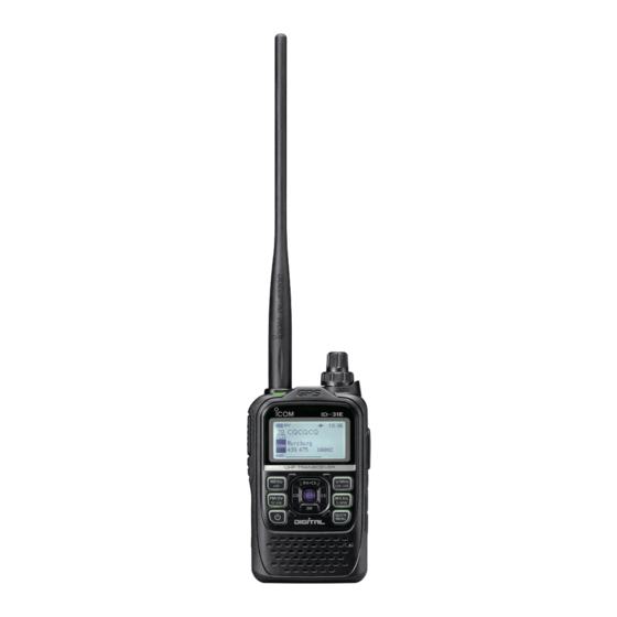
The photo shows the
ID-31E version.
Advertisement
Table of Contents

Subscribe to Our Youtube Channel
Related Manuals for Icom ID-31A


Summary of Contents for Icom ID-31A
- Page 1 INSTRUCTION MANUAL UHF TRANSCEIVER ID-31A UHF TRANSCEIVER ID-31E This device complies with Part 15 of the FCC Rules. Operation is subject to the following two conditions: (1) this device may not cause harmful interference, and (2) this device must accept any interference received, including interference that may cause undesired operation.
- Page 2 ❍ Voice recorder to records your communi- We thank you for making your ID-31A or ID-31E your radio of cation choice, and hope you agree with Icom’s philosophy of “tech- ❍ Waterproof construction (IPX7*) nology first.”...
-
Page 3: Explicit Definitions
This product uses a Coin Lithium Battery which contains Per- CAUTION: Changes or modifications to this device, not chlorate Material—special handling may apply. expressly approved by Icom Inc., could void your authority to operate this device under FCC regulations. See http://www.dtsc.ca.gov/hazardouswaste/perchlorate... - Page 4 Icom radios or Icom chargers. Only Icom battery ears, reduce the volume level or discontinue use. packs are tested and approved for use with Icom radios or R WARNING! NEVER charged with Icom chargers. Using third-party or counterfeit...
- Page 5 PRECAUTIONS CAUTION: DO NOT BE CAREFUL! use harsh solvents such as ben- The transceiver meets IPX7* require- zine or alcohol to clean the transceiver, because they can ments for waterproof protection. However, once the trans- damage the transceiver’s surfaces. ceiver has been dropped, waterproof protection cannot be guaranteed because of possible damage to the transceiver's DO NOT operate the transceiver near unshielded electri-...
-
Page 6: Important Notes When Using The Gps Receiver
• The GPS signal cannot pass through metal objects. When • The GPS receiver may not work if the transceiver operates using the ID-31A or ID-31E inside a vehicle, you may not near the 440.205 MHz. This is made in the internal circuit receive GPS signals. -
Page 7: About The Supplied Cd
ABOUT THE SUPPLIED CD D Starting the CD The following Guide, Instructions and Installers are included in the CD. Insert the CD into the CD drive. • The Menu screen shown below is automatically displayed. If • D-STAR Quick Guide it doesn’t appear, double click “Autorun.exe”... -
Page 8: Table Of Contents
SUPPLIED ACCESSORIES TABLE OF CONTENTS FOREWORD ................. i The following accessories are supplied with the transceiver. IMPORTANT ................i q Antenna ................1 FEATURES ................i w Hand strap ..............1 EXPLICIT DEFINITIONS ............ii e Battery charger (BC-167SA/SD/SV)* ......1 FCC INFORMATION ............ -
Page 9: Table Of Contents
TABLE OF CONTENTS 4 BATTERY CHARGING ..........11–18 6 MENU SCREEN OPERATION ........32–49 Caution ...............11 Menu item selection ...........32 ■ ■ Regular charging ............13 Menu items and default settings ........33 ■ ■ Rapid charging ............14 ■ 7 RESETTING ..............50 Optional battery case ..........15 ■... -
Page 10: Accessory Attachment
ACCESSORY ATTACHMENT ■ Hand strap ■ Battery pack To facilitate carrying the trans- To attach or detach the battery pack: ceiver, slide the hand strap To attach or detach the battery pack or battery case, follow through the loop on the top of the illustrations below. -
Page 11: Belt Clip
ACCESSORY ATTACHMENT ■ Belt clip ■ Antenna To attach the belt clip: Insert the antenna connector into the antenna base and tight- Remove the battery pack from the transceiver, if it is at- en the antenna base. tached. (p. 1) Antenna w Slide the belt clip in the direction of the arrow until the belt clip locks in place, and makes a ‘click’... -
Page 12: About Using A Microsd Card
GPS information, and other transceiver. Please purchase a desired card to use. data. Following data can be stored onto the card. Icom has checked compatibility with the following microSD and microSDHC cards, shown in the table. • Memory channel contents •... -
Page 13: Inserting The Microsd Card
ABOUT USING A MICROSD CARD ■ Inserting the microSD card ■ Format the microSD card Turn OFF the transceiver. When using a preformatted brand new microSD card, format- Lift OFF the [micro SD] slot cover on the side panel. ting is not necessary. However, we recommend you format it With the terminals facing the front, insert the card into the in the following way to get card’s best performance. -
Page 14: Panel Description
PANEL DESCRIPTION ■ Front, top and side panels q ANTENNA CONNECTOR (p. 2) Connect the antenna here. • An optional AD-92SMA adapter (p. 55) is available to connect an antenna with a BNC connector. w TX/RX INDICATOR [TX/RX] (pp. 24, 25) Lights green while receiving a signal or when the squelch is open;... - Page 15 PANEL DESCRIPTION y FM/DV • SCAN KEY [FM/DV•SCAN] !2 MEMORY/CALL • SELECT MEMORY WRITE KEY [M/CALL•S.MW] ➥ Push to select the operating mode. (p. 24) • Selectable operating modes are FM, FM-N and DV. ➥ In the VFO mode, push once to enter the Memory ➥...
- Page 16 PANEL DESCRIPTION Front, top and side panels (Continued) ■ EXTERNAL SPEAKER/MICROPHONE JACK [SP/MIC] Connect a cloning cable, optional speaker microphone or headset, if desired. See page 54 for a list of available options. Be sure to turn power OFF before connecting or discon- necting optional equipment to or from the [SP/MIC] jack.
- Page 17 PANEL DESCRIPTION D D-PAD CD (RX CALL RECORD)/LEFT KEY [CD] ➥ Hold down for 1 second to open the received calls record. ➥ While in the DR mode, or with the Menu screen or Quick Menu screen open, push to select an upper tier menu.
-
Page 18: Function Display
PANEL DESCRIPTION ■ Function display e DUPLEX ICON (p. 29) “DUP+” appears when plus duplex is selected, and “DUP–” t yu i appears when minus duplex is selected. r PRIORITY WATCH ICON Appears when Priority Watch is in use. See the PDF type Advanced Instruction’s Section 9 for more details. -
Page 19: Panel Description
PANEL DESCRIPTION • While operating in DV mode: !2 MEMORY CHANNEL NUMBER “ DSQL” appears while the Digital Call Sign squelch ➥ Displays the selected memory channel number. (p. 21) ➥ function is ON. “C0” or “C1” appears when the Call channel is selected. ➥... -
Page 20: Battery Charging
Icom radios or Icom chargers. Only Icom battery an explosion. packs are tested and approved for use with Icom radios or • R DANGER! NEVER solder the battery terminals, or charged with Icom chargers. Using third-party or counterfeit NEVER modify the battery pack. -
Page 21: D Charging Caution
If • R DANGER! NEVER charge the battery pack in areas with any of these conditions occur, contact your Icom dealer or extremely high temperatures, such as near fires or stoves, distributor. -
Page 22: Regular Charging
BATTERY CHARGING ■ Regular charging Prior to using the transceiver for the first time, the battery Transceiver • BC-167S to AC outlet pack must be fully charged for optimum life and operation. D Battery icon The BC-167SA, BC-167SD and When the transceiver’s power is OFF, the charging icon se- BC-167SV have quentially shows “... -
Page 23: Rapid Charging
BATTERY CHARGING Rapid charging ■ • Charging period: BP-271 approximately 2.0 hours The optional BC-202 rapidly charges of the BP-271 or BP-272 BP-272 approximately 3.5 hours Li-ion battery packs. Transceiver Charging note (with battery pack) Battery pack • Be sure to turn OFF the transceiver power. AC Adapter When the transceiver power cannot be turned OFF, detach (A different type, or... -
Page 24: Optional Battery Case
BATTERY CHARGING ■ Optional battery case Rapid charging (Continued) ■ IMPORTANT: Battery charging caution , install 3 × AA (LR6) When using the BP-273 battery case Ensure the guide rails on the battery pack are correctly size alkaline batteries, as described below. aligned with the tabs inside the charger. - Page 25 BATTERY CHARGING CAUTION: • When installing batteries, make sure they are all the same brand, type and capacity. Also, do not mix new and old batteries together. • Keep the battery terminals clean. It’s a good idea to peri- odically clean the battery terminals. •...
-
Page 26: Battery Information
BATTERY CHARGING ■ Battery information D Battery life D Battery icon The transceiver operates with the BP-271 or BP-272 Li-ion The “ ” battery icon appears when the BP-271 or BP-272 battery packs, as follows. Li-ion battery pack is attached to the transceiver. When operating in the DV mode, the operating time may be shortened by one-half hour. -
Page 27: External Dc Power Operation
BATTERY CHARGING ■ External DC power operation Transceiver • CP-12L (Optional) An optional CP-12L or CP-19R cigarette lighter cable, for a 12 V cigarette lighter socket, or an OPC-254L external DC power cable can be used for external power. D Operating note to a cigarette lighter •... -
Page 28: Basic Operation
BASIC OPERATION ■ Power ON ■ Setting audio volume Rotate [VOL] to adjust the audio level. Hold down for 1 second to turn ON power. ➥ ➥ • If the squelch is closed, hold down [SQL] while setting the audio •... -
Page 29: Setting Squelch Level
BASIC OPERATION ■ Setting squelch level ■ Monitor function The squelch function mutes the noise or received audio sig- This function is used to listen to weak signals without disturb- nal, depending on the signal strength and the squelch control ing the squelch setting, or having to open the squelch manu- setting to cut off the noise output. -
Page 30: Mode Selection
BASIC OPERATION ■ Mode selection D Memory mode D VFO mode Memory mode is used for operation on memory channels, The VFO mode is used to set the desired frequency. which store programmed frequencies. Push [V/MHz] to select the VFO mode. ➥... -
Page 31: Dr (D-Star Repeater) Mode
BASIC OPERATION D DR (D-STAR Repeater) mode D Call channels The DR (D-STAR Repeater) mode is used for D-STAR re- Call channels are used for quick recall of most-often used peater operation. In this mode, you can easily select the pre- frequencies. -
Page 32: Setting A Tuning Step
BASIC OPERATION ■ Setting a tuning step ■ Setting a frequency The following tuning steps are selectable. q Push [V/MHz] to select VFO mode, if necessary. • 5.0 kHz • 6.25 kHz • 10.0 kHz • 12.5 kHz w Rotate [DIAL] to select the desired frequency. •... -
Page 33: Operating Mode Selection
BASIC OPERATION ■ Operating mode selection ■ Receiving Operating modes are determined by the modulation of the Make sure a charged BP-271 or BP-272 battery pack, or a radio signals. The transceiver has a total of three operating BP-273 battery case with brand new alkaline batteries is at- modes;... -
Page 34: Transmitting
BASIC OPERATION ■ Transmitting R WARNING! NEVER transmit for long periods of time. CAUTION: Transmitting without an antenna will damage the During prolonged transmissions at high power or middle transceiver. power, the transceiver radiates heat to protect itself from overheating. The transceiver’s chassis will become hot and NOTE: To prevent interfering, hold down [SQL] to listen on may cause a burn. -
Page 35: Transmit Power Selection
BASIC OPERATION ■ Transmit power selection ■ Key Lock function The transceiver has four output power levels to suit your op- Activate to prevent accidental frequency changes and unnec- erating requirements. Lower output power during short-range essary function access. communications may reduce the possibility of interference to other stations and will conserve battery power. -
Page 36: Scan Function
BASIC OPERATION ■ Scan function Scanning is a versatile function that can automatically search About the scanning steps: The selected tuning step in for signals, and makes it easier to locate stations to contact the VFO mode is used during scan. or listen to, or to skip unwanted frequencies. -
Page 37: Memory Channel Programming
BASIC OPERATION ■ Memory channel programming The Memory mode is very useful to quickly select often-used r Rotate [DIAL] to select a desired operating settings. channel. • Call channels (C0, C1), VFO and scan [Example]: Programming 433.600 MHz/FM mode into edge channels (00A/00B to 24A/24B), memory channel 11 (a blank channel). -
Page 38: Repeater Operation
BASIC OPERATION ■ Repeater operation If desired, activate the subaudible tone encoder in the When using a repeater, the transmit frequency is shifted from Quick Menu (see next page for details). the receive frequency by the frequency offset (p. 33). This is called duplex operation. -
Page 39: Setting The Duplex Direction
BASIC OPERATION D Setting the duplex direction D Setting the subaudible tone In the VFO mode, push to open q In the VFO mode, push to open the Quick Menu screen. the Quick Menu screen. Push D-pad( #) to select the “DUP” Push D-pad( E) to select the “TONE”... -
Page 40: Basic Operation
BASIC OPERATION ■ Band Scope function D Sweep operation The Band Scope function allows you to visually check a spec- Push to open the Quick Menu ified frequency range around the center frequency. screen. The receive audio during sweeping can be muted in SOUNDS menu. -
Page 41: Menu Screen Operation
MENU SCREEN OPERATION ■ Menu item selection Entering the Menu screen and operation The MENU screen is used for programming infrequently changed values or function settings. In addition to this page, see pages 33 through 49 for details Example: Set the Auto Power OFF function to “30 min.” of each item’s options and their default value. -
Page 42: Menu Items And Default Settings
MENU SCREEN OPERATION ■ Menu items and default settings NOTE: The default settings, shown below, are for the USA version. The default settings may differ, depending on the version. In this item, set the repeater options, for example duplex offset or the channel tone types. DUP/TONE... - Page 43 MENU SCREEN OPERATION NOTE: The default settings, shown below, are for the USA version. The default settings may differ, depending on the version. In this item, set the scan options. Scan RANGE OR VALUE (Default is shown in bold) DESCRIPTIONS Selects the scan pause time.
- Page 44 MENU SCREEN OPERATION ■ Menu items and default settings (Continued) NOTE: The default settings, shown below, are for the USA version. The default settings may differ, depending on the version. Voice Memo In this item, set the TX/RX voice recording options. RANGE OR VALUE (Default is shown in bold) DESCRIPTIONS Starts recording the received signal audio.
- Page 45 MENU SCREEN OPERATION NOTE: The default settings, shown below, are for the USA version. The default settings may differ, depending on the version. In this item, set the GPS options. RANGE OR VALUE (Default is shown in bold) DESCRIPTIONS Selects a GPS receiver that the trans- GPS Set GPS Select OFF, Internal GPS,...
- Page 46 MENU SCREEN OPERATION ■ Menu items and default settings (Continued) NOTE: The default settings, shown below, are for the USA version. The default settings may differ, depending on the version. GPS (Continued) In this item, set the GPS options. RANGE OR VALUE (Default is shown in bold) DESCRIPTIONS Displays the received GPS information.
- Page 47 MENU SCREEN OPERATION NOTE: The default settings, shown below, are for the USA version. The default settings may differ, depending on the version. GPS (Continued) In this item, set the GPS options. GPS TX Mode RANGE OR VALUE (Default is shown in bold) DESCRIPTIONS Enters an unproto Address.
- Page 48 MENU SCREEN OPERATION ■ Menu items and default settings (Continued) NOTE: The default settings, shown below, are for the USA version. The default settings may differ, depending on the version. Call Sign In this item, set and display the call signs used in the DV mode. DESCRIPTIONS Displays the operating call signs.
- Page 49 MENU SCREEN OPERATION NOTE: The default settings, shown below, are for the USA version. The default settings may differ, depending on the version. My Station In this item, set your own call sign to use in the DV mode. RANGE OR VALUE (Default is shown in bold) DESCRIPTIONS Stores and selects Your own call signs.
- Page 50 MENU SCREEN OPERATION ■ Menu items and default settings (Continued) NOTE: The default settings, shown below, are for the USA version. The default settings may differ, depending on the version. DV Set (Continued) In this item, set infrequently changed values or functions in the DV mode. RANGE OR VALUE (Default is shown in bold) DESCRIPTIONS Selects the Automatic Reply function ON,...
- Page 51 MENU SCREEN OPERATION NOTE: The default settings, shown below, are for the USA version. The default settings may differ, depending on the version. DV Set (Continued) In this item, set infrequently changed values or functions in the DV mode. RANGE OR VALUE (Default is shown in bold) DESCRIPTIONS Turns the BK (Break-in) function ON or OFF or ON...
- Page 52 MENU SCREEN OPERATION ■ Menu items and default settings (Continued) NOTE: The default settings, shown below, are for the USA version. The default settings may differ, depending on the version. In this item, set the Speech functions. SPEECH RANGE OR VALUE (Default is shown in bold) DESCRIPTIONS Selects the RX call sign speech function RX Call Sign SPEECH...
- Page 53 MENU SCREEN OPERATION NOTE: The default settings, shown below, are for the USA version. The default settings may differ, depending on the version. In this item, set other options. Function RANGE OR VALUE (Default is shown in bold) DESCRIPTIONS Selects the Power Save options to re- Power Save OFF, Auto (Short), Auto (Middle) or Auto (Long) duce current drain and conserve battery...
- Page 54 MENU SCREEN OPERATION ■ Menu items and default settings (Continued) NOTE: The default settings, shown below, are for the USA version. The default settings may differ, depending on the version. Function (Continued) In this item, set other options. RANGE OR VALUE (Default is shown in bold) DESCRIPTIONS Sets the internal microphone sensitivity MIC Gain (Internal)
- Page 55 MENU SCREEN OPERATION NOTE: The default settings, shown below, are for the USA version. The default settings may differ, depending on the version. Function (Continued) In this item, set other options. RANGE OR VALUE (Default is shown in bold) DESCRIPTIONS Sets the transceiver's unique CI-V hexa- CI-V CI-V Address...
- Page 56 MENU SCREEN OPERATION ■ Menu items and default settings (Continued) NOTE: The default settings, shown below, are for the USA version. The default settings may differ, depending on the version. Display In this item, set the Display options. RANGE OR VALUE (Default is shown in bold) DESCRIPTIONS Selects to display and scroll a received OFF or Auto...
- Page 57 MENU SCREEN OPERATION NOTE: The default settings, shown below, are for the USA version. The default settings may differ, depending on the version. Sounds In this item, set the Sound options. RANGE OR VALUE (Default is shown in bold) DESCRIPTIONS Sets the beep output level.
- Page 58 MENU SCREEN OPERATION ■ Menu items and default settings (Continued) SD Card* In this item, set the microSD card options. RANGE OR VALUE (Default is shown in bold) DESCRIPTIONS Loads the settings file to the trans- Setting Load File selection ALL, Except My Station, ceiver.
-
Page 59: Resetting
RESETTING ■ Resetting D Partial reset D All reset The display may occasionally display q Hold down for 1 second to turn q Hold down for 1 second to turn erroneous information (e.g. when first applying power). This may be caused OFF power. -
Page 60: Troubleshooting
TROUBLESHOOTING If your transceiver seems to be malfunctioning, please check the following points before sending it to a service center. PROBLEM POSSIBLE CAUSE SOLUTION REF. Transceiver does not turn • The battery is exhausted. • Charge the battery pack, or replace the batteries. pp. - Page 61 TROUBLESHOOTING • While operating D-STAR PROBLEM POSSIBLE CAUSE SOLUTION REF. After your call, the repeater • The repeater setting is wrong. • Set the correct repeater. Advanced does not transmit a reply. • Correct the repeater frequency, frequency offset, or Instruction duplex setting.
-
Page 62: Specifications
: 10.0–16.0 V DC for external DC power, (PN9/GMSK 4.8 kbps; BER 1%) • Audio output power (at 10% distortion) or specified Icom’s battery pack : More than 0.4 W with a 16 Ω load Internal speaker • Digital transmission speed : 4.8 kbps : More than 0.2 W with a 8 Ω... -
Page 63: Options
OPTIONS • BP-271 • HM-153LS/HM-166LS ion battery pack earphone microphone Ideal for hands-free operation: clip the HM-153LS/HM-166LS 7.4 V/1150 mAh (Min.)/1200 mAh (Typ.) Lithium ion battery (with integrated PTT switch) to your lapel or breast pocket. pack. Battery life: 4.5 hours (approximately; FM, high power, TX Allows you to operate in rainy condition. - Page 64 Approved Icom optional equipment is designed for optimal performance when used with an Icom transceiver. Icom is not responsible for the destruction or damage to an Icom transceiver in the event the Icom transceiver is used with equipment that is not manufactured or approved by Icom.
-
Page 65: Optional Hm-75Ls
OPTIONS ■ Optional HM-75LS remote control speaker microphone The optional HM-75LS allows you to remotely select operat- • SIMPLE: ing frequencies, memory channels, etc. Toggles the Monitor function Turns the Call channel mode Remote control functions can be selected from three settings. [p] Select memory channel 0 These can be selected with “MIC Simple Mode”... -
Page 66: Carrying Case
OPTIONS ■ LC-178 HM-75LS ■ remote control speaker microphone carrying case (Continued) CAUTION: • COMMON (SIMPLE/NORM-1/NORM-2): When removing the carrying case from the transceiver, Transmits T-CALL (1750 Hz tone) while pushing [PTT] slide the side parts to the direction of the arrows. —... -
Page 67: Vox Function
OPTIONS ■ VOX function The transceiver has a VOX function, which allows hands-free D Selecting the headset type operation. Turn ON the transceiver. An optional HS-94, HS-95 or HS-97 headset and the OPC- Push [MENU] to enter the Menu screen. 2006LS plug adapter cable are also required. - Page 68 OPTIONS D Turning the VOX function ON or OFF D VOX-related settings Push [MENU] to enter the The VOX Level, the VOX Delay, and the VOX time-out timer Menu screen. can be set in the Menu screen. Push D-pad( E) to select the root item (Function), and then push D- VOX Level •...
- Page 69 OPTIONS ✔ CONVENIENT! VOX time-out timer • While transmitting using the VOX func- Sets the VOX Time-Out Timer to between 1, 2, 3, 4, 5, 10 and tion, you can adjust the VOX gain sim- 15 minutes to prevent accidental prolonged transmission. ply by rotating [DIAL].
-
Page 70: Country Code List
COUNTRY CODE LIST • ISO 3166-1 Country Codes Country Codes Austria Liechtenstein Belgium Lithuania Bulgaria Luxembourg Croatia Malta Czech Republic Netherlands Cyprus Norway Denmark Poland Estonia Portugal Finland Romania France Slovakia Germany Slovenia Greece Spain Hungary Sweden Iceland Switzerland Ireland Turkey Italy United Kingdom... -
Page 71: Index
INDEX Charging note ………………………………………… 13, 14 ABOUT SUPPLIED CD …………………………………… Charging period (Rapid charging) ………………………… 14 About using a microSD card ……………………………… Charging period (Regular charging) ……………………… 13 ACCESSORY ATTACHMENT …………………………… CLEAR KEY ………………………………………………… All reset ……………………………………………………… 50 CLOCK DISPLAY …………………………………………… 10 Antenna ………………………………………………………... - Page 72 INDEX EXPLICIT DEFINITIONS ………………………………… Inserting the microSD card ………………………………… EXTERNAL DC IN JACK ………………………………… External DC power operation ……………………………… 18 EXTERNAL SPEAKER/MICROPHONE JACK ………… Key Lock function …………………………………………… 26 FCC INFORMATION ……………………………………… LC-178 …………………………………… 57 carrying case FEATURES …………………………………………………… i LEFT KEY ……………………………………………………...
-
Page 73: Optional Hm-75Ls Remote Control Speaker Microphone
INDEX Receiver ……………………………………………………… 53 Receiving …………………………………………………… 24 OPERATING MODE ICONS ……………………………… Regular charging …………………………………………… 13 Operating mode selection ………………………………… 24 Repeater operation ………………………………………… 29 Operating note ……………………………………………… 18 Resetting …………………………………………………… 50 Optional battery case ……………………………………… 15 RF METER ………………………………………………… 10 Optional HM-75LS RIGHT KEY …………………………………………………... - Page 74 INDEX SUPPLIED ACCESSORIES ……………………………… vii Sweep operation …………………………………………… 31 TONE ICONS ……………………………………………… Transmit power selection …………………………………… 26 Transmitter …………………………………………………… 53 Transmitting ………………………………………………… 25 TROUBLESHOOTING ……………………………………… 51 Tuning step selection ……………………………………… 23 Turning the VOX function ON or OFF …………………… 59 TX/RX INDICATOR …………………………………………...
- Page 75 MEMO...
- Page 76 MEMO...
- Page 77 MEMO...
- Page 78 MEMO...
- Page 79 MEMO...
- Page 80 ■ ■ ■ ■ ■ ■ ■ ■ ■ ■ ■ ■ ■ ■ ■ ■ ■ ■ ■ A-6986H-1EX-w Printed in Japan 2011–2014 Icom Inc. © 1-1-32 Kamiminami, Hirano-ku, Osaka 547-0003, Japan Printed on recycled paper with soy ink.
Need help?
Do you have a question about the ID-31A and is the answer not in the manual?
Questions and answers