Intermec Sabre 1552 Scanner System Manual
Scanner and base station
Hide thumbs
Also See for Sabre 1552 Scanner:
- User manual (20 pages) ,
- Supplementary manual (8 pages) ,
- Instructions (2 pages)
Table of Contents
Advertisement
Quick Links
Advertisement
Table of Contents
Troubleshooting

Related Manuals for Intermec Sabre 1552 Scanner


Summary of Contents for Intermec Sabre 1552 Scanner
- Page 1 System Manual Sabre 1552 Scanner and Microbar 9745 Base Station...
- Page 2 The information contained herein is proprietary and is provided solely for the purpose of allowing customers to operate and service Intermec-manufactured equipment and is not to be released, reproduced, or used for any other purpose without written permission of Intermec.
- Page 3 This page records the changes to this manual. The manual was originally released as version 001. Version Date Description of Change 11/01 Updated document to current Intermec style. 3/02 Updated for advanced long-range scanner. 3/05 Corrected the Show Data Formats bar code, the human readable text for the Code 39 test bar code, and the FB command description.
- Page 4 blank...
-
Page 5: Table Of Contents
Contents Contents Before You Begin xi Safety Summary xii Safety Icons xii Global Services and Support xiii Who Should Read This Document? xiiiv Related Documents xiv Getting Started About the Cordless System 1-3 Scanner: Main Components 1-4 Base: Back View 1-4 Battery Pack 1-5 North American Charging Information 1-5 Worldwide Charging Information 1-5... - Page 6 Sabre 1552 Scanner and MicroBar 9745 Base Station System Manual Communication Between the Cordless System and the Host 1-17 Acknowledgement from the Base 1-17 Acknowledgement from the Host System 1-18 Quick Start and Interface Menu Introduction 2-3 Plug and Play Selections 2-4...
- Page 7 Contents Communications Menu Host Port Communications 3-3 Baud Rate Selection 3-3 Parity Selection 3-4 Word Length Data Bits Selection 3-5 Word Length Stop Bits Selection 3-5 Serial Wedge Output Selection 3-6 Hardware Flow Control Selection 3-6 Host ACK Selection 3-7 Escape Commands 3-7 Auxiliary Port Communications 3-8 Baud Rate Selection 3-8...
- Page 8 Sabre 1552 Scanner and MicroBar 9745 Base Station System Manual Application Work Groups Menu Introduction 4-3 Output Selections 4-4 Application Work Group Selection 4-4 Remove Scanner Selection 4-5 Beeper Volume Selection 4-5 Beeper Pitch 4-6 Decode Beep Selection 4-7 Scanner Voting Selection 4-7...
- Page 9 Contents Symbology Menu Industrial Symbology Selections 5-3 Codabar Selection 5-3 Concatenation 5-5 Code 39 Selection 5-6 Code 93 Selection 5-9 Interleaved 2 of 5 Selection 5-10 Code 2 of 5 Selection 5-11 Matrix 2 of 5 Selection 5-12 Code 11 Selection 5-13 Code 128 Selection 5-14 Telepen Selection 5-15 Retail Symbology Selections 5-16...
- Page 10 Sabre 1552 Scanner and MicroBar 9745 Base Station System Manual Specifications and Factory Defaults Sabre 1552 Scanner Specifications 8-3 Battery Specifications 8-4 NiMH Battery Pack: Recommended Storage 8-4 MicroBar 9745 Base Station Specifications 8-5 Radio Specifications 8-5 Connectors and Pinouts 8-6...
-
Page 11: Before You Begin
Your safety is extremely important. Read and follow all warnings and cautions in this document before handling and operating Intermec equipment. You can be seriously injured, and equipment and data can be damaged if you do not follow the safety warnings and cautions. -
Page 12: Safety Icons
Global Services and Support Warranty Information To understand the warranty for your Intermec product, visit the Intermec web site at www.intermec.com and click Service & Support. The Intermec Global Sales &... -
Page 13: Who Should Read This Document? Xiiiv
IP address. Related Documents The Intermec web site at www.intermec.com contains our current documents that you can download as PDF files. To order printed versions of the Intermec manuals, contact your local Intermec representative or distributor. xiii... -
Page 15: Getting Started
Getting Started... - Page 16 Sabre 1552 Scanner and MicroBar 9745 Base Station System Manual blank...
-
Page 17: About The Cordless System
Getting Started This chapter explains the Cordless System and its components. It also describes how to charge the batteries and get the system installed and running. About the Cordless System The Cordless System consists of the MicroBar 9745 Cordless Base Station and at least one Sabre 1552 Cordless Scanner. -
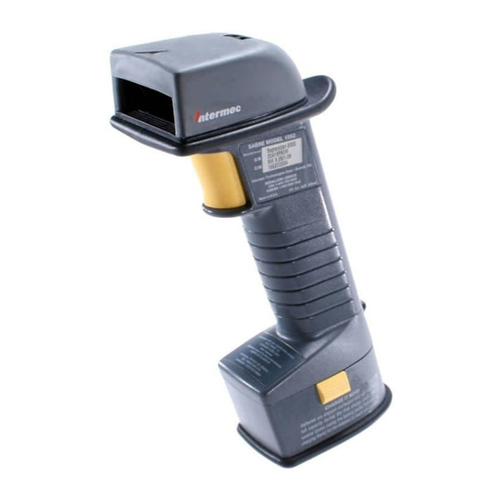
Page 18: Scanner: Main Components
Sabre 1552 Scanner and MicroBar 9745 Base Station System Manual Scanner: Main Components Audio - sound Light port Scan window Trigger Battery pack clip (2 places) Battery pack 1552S013.eps Base: Back View Antenna External power connector (power port optional) Keyboard/terminal... -
Page 19: Battery Pack
The charge strip is offered for two or six battery pack configurations. Contact your local Intermec representative for more information on charge strips. Battery Pack Recommendations •... -
Page 20: Proper Disposal Of The Battery Pack
Sabre 1552 Scanner and MicroBar 9745 Base Station System Manual Proper Disposal of the Battery Pack When the battery pack has reached the end of its useful life, the batteries should be disposed of by a qualified recycler or hazardous materials handler. Do not incinerate the battery pack or dispose of the battery pack with general waste materials. -
Page 21: Accessories For The Cordless System
Getting Started Accessories for the Cordless System Contact your local Intermec representative for more information or to order accessories. Battery Packs The permanently sealed battery packs contain four rechargeable “AA” cells, plus circuitry to allow recharging via standard AC power outlets (eliminating cumbersome and expensive custom charging stations). -
Page 22: Setting Up The Cordless System
Sabre 1552 Scanner and MicroBar 9745 Base Station System Manual Setting Up the Cordless System Important: Before you set up the Cordless System, make sure the scanner’s battery pack has been fully charged. See “Charging the Battery Pack” earlier in this chapter for charging instructions. - Page 23 In an RS-232 configuration, connect your interface cable between the base (1) and the host system (2). You also need to use an external power supply (3). Contact your Intermec sales representative for more information on ordering power supplies or RS-232 cables, including “Y” extension and mouse power pickup cables to mount the base for best RF coverage.
- Page 24 Sabre 1552 Scanner and MicroBar 9745 Base Station System Manual 4. Using the scanner, scan the Association Bar Code (the bar code label on the top of the base) to link that scanner to the base. Two quick beeps followed by clicking and a single beep indicates a “good”...
-
Page 25: Connecting More Scanners To The Cordless System
Getting Started Connecting More Scanners to the Cordless System Up to nine scanners may be associated with one base To connect more scanners to the Cordless System 1. Make sure the scanner’s battery pack has been fully charged. 2. Scan the Association Bar Code (the bar code label on the top of the base) to link each scanner to the base. -
Page 26: Understanding The Scanner Led
Sabre 1552 Scanner and MicroBar 9745 Base Station System Manual Understanding the Scanner LED Sequence Meaning Green LED on Trigger pulled, out of range Green LED on, 2 seconds Successful decode and communication Green LED blinks, 2 seconds Successful decode with unsuccessful communication, or... -
Page 27: Basic Operation Of The Cordless System
Getting Started Basic Operation of the Cordless System This section explains the basic operating components of the Cordless System. Base The base provides the link between the scanner and the host system. The base contains a control/interface assembly and an RF communication module. The RF communication module performs the data exchange between the scanner and the control/interface assembly. -
Page 28: Rf (Radio Frequency) Module Operation
Sabre 1552 Scanner and MicroBar 9745 Base Station System Manual RF (Radio Frequency) Module Operation The Cordless System uses a state of the art radio to transmit and receive data between the scanner and the base. Designed for point-to-point and multipoint to single point applications, the radio transmits data at a rate of 1 megabit per second (Mbps) in a half duplex (2 way) communications mode. -
Page 29: System Conditions
Getting Started Scanner Scanner Assembly Engine Assembly Decode/Control Assembly (handle board) Scan engine Trigger (laser) HHLC I/O handle Engine port housing Control Menu I/O Beeper Trig/decode Power mgmt Beeper port Antenna RF module Engine hsg RF port window/lt pipe download port Battery port 1552S022.eps Battery pack... -
Page 30: Scanner Is Out Of Range
Sabre 1552 Scanner and MicroBar 9745 Base Station System Manual Scanner is Out of Range The scanner is always in communication with its base, even when it is not transmitting bar code data. Whenever the scanner can’t communicate with the base for a 3-second interval, it is out of range. -
Page 31: Swapping Scanners Between Two Systems With Nine Scanners On Each
Getting Started Each base keeps an association list of up to nine scanners. This list contains the associated scanners’ radio serial numbers and dynamic addresses. New dynamic addresses are assigned to the scanners each time a base Reset occurs. This helps the Cordless System track the status of the different scanners in its network during the association and reassociation process. -
Page 32: Acknowledgement From The Host System
Sabre 1552 Scanner and MicroBar 9745 Base Station System Manual Acknowledgement From the Host System Host system confirmation may be implemented with a bi-directional interface like Host RS-232. In this configuration, when the base receives the scanned data from the scanner and forwards it to the host, the Cordless System waits for a signal from the host that it received the data. -
Page 33: Quick Start And Interface Menu
Quick Start and Interface Menu... - Page 34 Sabre 1552 Scanner and MicroBar 9745 Base Station System Manual blank...
-
Page 35: Introduction
Quick Start and Interface Menu This chapter explains how to program the Cordless System to work with your terminal or computer (host system). Introduction All operating parameters are stored in non-volatile memory resident in the Cordless System, where they are permanently retained in the event of a power interruption. When you receive your Cordless System, certain operating parameters have already been set. -
Page 36: Plug And Play Selections
Sabre 1552 Scanner and MicroBar 9745 Base Station System Manual Plug and Play Selections This section contains programming bar codes for: • Industrial Interface: IBM PC • Industrial Interface, Aux Port: RS-232 • IBM 468X/9X Ports 5B, 9B, and 17 Interface •... -
Page 37: Ibm 468X/9X Ports 5B, 9B, And 17 Interface
Quick Start and Interface Menu IBM 468X/9X Ports 5B, 9B, and 17 Interface Scan one of the following “Plug and Play” bar codes to program the interface for IBM 4683 Port 5B, 9B, or 17. Note: When using any of the IBM 4683 interfaces, the maximum allowable data rate into the base aux port is 9600 baud. -
Page 38: White High
Sabre 1552 Scanner and MicroBar 9745 Base Station System Manual Industrial Interface, Aux Port: Wand Emulation Black High (continued) These bar codes also program the following parameters: Programmable Option Setting Transmission Rate 25 inches per second Output Polarity Black High... -
Page 39: Terminal Interface Selections
Quick Start and Interface Menu Terminal Interface Selections If your terminal is not one of the Plug and Play options, you must program one of the terminals listed below. To program the terminal interface 1. Scan the Program Terminal Interface bar code. Program Terminal Interface 2. - Page 40 Sabre 1552 Scanner and MicroBar 9745 Base Station System Manual Supported Terminals (continued) Terminal Model(s) Terminal ID IBM 102 Key 3151, 3161, 3162, 3163, 3179, 3191, 3192, 3194, 3196, 3197, 3471, 3472, 3476, 3477, 3482, 3486, 3488 IBM 122 Key...
-
Page 41: Keyboard Country Selection
Quick Start and Interface Menu Keyboard Country Selection This programming selection lets you remap the keyboard layout for the selected country. As a general rule, the following characters are not supported by the Cordless System for countries other than the United States: @ | $ # { } [ ] = / ` \ <... -
Page 42: Keyboard Selections
Sabre 1552 Scanner and MicroBar 9745 Base Station System Manual Keyboard Country Selection (continued) Denmark (Wyse only) Keyboard Selections This section contains programming bar codes for: • Keyboard Style Selections • Keyboard Style Modifiers Keyboard Style Selections This programming selection lets you program special keyboard features, such as Caps Lock and Shift Lock. -
Page 43: Keyboard Style Modifiers
Quick Start and Interface Menu Keyboard Style Selections (continued) Automatic Caps Lock Emulate External Keyboard (Laptops) Keyboard Style Modifiers This programming selection lets you program special keyboard features, such as Ctrl+ codes and Turbo Mode. Control+ASCII Mode Selecting Control+ASCII Mode On makes the Cordless System send key combinations for ASCII control characters for values 00-1F. - Page 44 Sabre 1552 Scanner and MicroBar 9745 Base Station System Manual Keyboard Style Modifiers (continued) * Turbo Mode Off Numeric Keypad Mode On * Numeric Keypad Mode Off Automatic Direct Connect Mode On * Automatic Direct Connect Mode Off 2-12...
-
Page 45: Output Delays Selections
Quick Start and Interface Menu Output Delays Selections This selection provides control of the time delays between data output by the Cordless System to the host terminal. The actual delay is 5 ms multiplied by the programmed value (00 - 99). Default = 00. Intercharacter Delay is the time delay between data characters output by the Cordless System to the host terminal. -
Page 46: Wand Emulation Selections
Sabre 1552 Scanner and MicroBar 9745 Base Station System Manual Wand Emulation Selections This section contains programming bar codes for: • Transmission Rate Selection • Output Polarity Selection Transmission Rate Selection This programming selection sets the transmission rate from 10 ips (inches per second) to 300 ips if the Cordless System is in Wand Emulation mode. -
Page 47: Output Polarity Selection
Quick Start and Interface Menu Transmission Rate Selection (continued) Output Polarity Selection This selection lets you set the output logic convention for the digital output. The choices are White High (“Laser” output) and Black High. White High *Black High 2-15... -
Page 48: Power Settings
Sabre 1552 Scanner and MicroBar 9745 Base Station System Manual Power Settings This section contains programming bar codes for: • Base Lower Power Mode • Battery Conservation Mode • Timeout Selections Base Low Power Mode You may want the base to draw less power when it is being powered by a portable data terminal or laptop. -
Page 49: Timeout Selections
Quick Start and Interface Menu Battery Conservation Mode (continued) No Timeout Scan this bar code if you want the scanner to remain on, which drains the battery faster than the other settings. Don’t Check for Network Base Before Timeout Check for Network Base Before Timeout *No Timeout Timeout Selections Timeout after 15 minutes... -
Page 50: Reset And Status Check Selections
Sabre 1552 Scanner and MicroBar 9745 Base Station System Manual Reset and Status Check Selections This section contains programming bar codes for: • Reset Factory Settings • Status Check Reset Factory Settings Scanning the Factory Default Settings bar code resets the Cordless System to the original factory settings, clearing any programming changes you may have made. - Page 51 Quick Start and Interface Menu Status Check (continued) Show Base Software Revision Show Scanner Software Revision 2-19...
- Page 52 Sabre 1552 Scanner and MicroBar 9745 Base Station System Manual blank 2-20...
-
Page 53: Communications Menu
Communications Menu... - Page 54 Sabre 1552 Scanner and MicroBar 9745 Base Station System Manual blank...
-
Page 55: Host Port Communications
Communications Menu This chapter explains how to program the communications parameters for the Cordless System. These parameters include host port communications, auxiliary port communications, auxiliary prefix and suffix selections, and auxiliary data formatter selections. Host Port Communications *Default All Host Port Communications Baud Rate Selection This selection sets the baud rate. -
Page 56: Parity Selection
Sabre 1552 Scanner and MicroBar 9745 Base Station System Manual Baud Rate Selection (continued) 19200 *38400 Parity Selection This selection provides a means of checking character bit patterns for validity. The host terminal must be set up for the same parity as the Cordless System to ensure reliable communication. -
Page 57: Word Length Data Bits Selection
Communications Menu Word Length Data Bits Selection This selection sets the word length at seven or eight bits of data per character. If an application requires only ASCII hex characters 0 through 7F decimal (text, digits, and punctuation), select 7 data bits. If an application requires the use of the full ASCII set, select 8 data bits per character. -
Page 58: Serial Wedge Output Selection
Sabre 1552 Scanner and MicroBar 9745 Base Station System Manual Serial Wedge Output Selection This selection selects the serial output direction required by your application. P1 and P2 are serial wedge designations printed on the serial wedge cable. Usually, one goes to the host and one goes to the terminal, depending on your specific application and the serial wedge cable. -
Page 59: Host Ack Selection
Communications Menu Host ACK Selection This selection programs the Cordless System to wait for a confirmation signal (ACK) from the host after bar code data has been sent. When Host ACK is turned on, the host system must be programmed to generate Escape Commands (see section below) for user feedback. -
Page 60: Auxiliary Port Communications
Sabre 1552 Scanner and MicroBar 9745 Base Station System Manual Escape Commands (continued) Command Action Esc a Beep (two high tones), illuminate green LED for 2 seconds Esc b Beep (three low tones), illuminate green LED nine times Esc 1... -
Page 61: Parity Selection
Communications Menu Baud Rate Selection (continued) 1200 2400 4800 9600 19200 *38400 Parity Selection This selection provides a means of checking character bit patterns for validity. The device connected to the auxiliary port must be set up for the same parity as the auxiliary port to ensure reliable communication. -
Page 62: Word Length Data Bits Selection
Sabre 1552 Scanner and MicroBar 9745 Base Station System Manual Parity Selection (continued) Mark Even Word Length Data Bits Selection This selection sets the word length at seven or eight bits of data per character. If an application requires only ASCII hex characters 0 through 7F decimal (text, digits, and punctuation), select 7 data bits. -
Page 63: Protocol Selection
Communications Menu Protocol Selection This selection programs the auxiliary port for the protocol required by the input device to the auxiliary port. The protocol is a set of rules concerning the exchange of data between serially communicating devices. The auxiliary port supports Record, Burst, and Ack/Nak protocols when receiving data from an RS-232 device. -
Page 64: Ibm 4683 Async Address Selections
Sabre 1552 Scanner and MicroBar 9745 Base Station System Manual IBM 4683 Async Address Selections If you are going to program the interface for IBM 4683 Async Addresses, you must first program the Terminal ID as 51 (see “Terminal Interface Selections” in Chapter 2). -
Page 65: Hardware Flow Control Selection
Communications Menu Hardware Flow Control Selection This selection turns on hardware flow control that checks for a CTS signal before sending data. This option is useful when your application supports the CTS signal. *Off Note: The auxiliary port receive function will only work properly if RTS/CTS or ACK/NAK flow control is used. -
Page 66: Aux Prefix And Suffix Selections
Sabre 1552 Scanner and MicroBar 9745 Base Station System Manual Data Character Selection (continued) SOB (Start of Block) EOB (End of Block) Aux Prefix and Suffix Selections Auxiliary prefix and suffix characters are data characters you may assign to incoming auxiliary port data. - Page 67 Communications Menu 2. Scan two bar codes for the hex value “72” (“r,” which represents the identifier for the Aux Port). Scan the two digits from the “Programming Chart” in Appendix A. 3. Refer to the Hex to ASCII Conversion Chart to find the hex value that represents the ASCII characters you wish to attach to the data.
-
Page 68: Aux Prefix Selection
Sabre 1552 Scanner and MicroBar 9745 Base Station System Manual Hex to ASCII Conversion Chart ASCII Hex ASCII Hex ASCII Hex ASCII Hex ASCII Hex ASCII Hex ASCII Hex ASCII Hex ‘ ” NAK 15 ACK 06 & ’ CAN 18 <... -
Page 69: Aux Suffix Selection
Communications Menu Aux Suffix Selection Add Aux Suffix Default Aux Suffix (CR) Clear All Aux Suffixes Exit Selection for Aux Prefix / Suffix Save Discard Aux Prefix Enable/Disable These codes are used when you want to toggle between turning on and off the prefix formatting. -
Page 70: Aux Suffix Enable/Disable
Sabre 1552 Scanner and MicroBar 9745 Base Station System Manual Aux Suffix Enable/Disable These codes are used when you want to toggle between turning on and off the suffix formatting. Enable Aux Suffix Disable Aux Suffix Aux Data Formatter Selections The Aux Data Format Editor selections are used to edit incoming data to the auxiliary port. - Page 71 Communications Menu 3. Terminal Type Refer to the “Terminal Interface Selections” in Chapter 2 and locate the terminal ID number for your PC. Scan three numeric bar codes from the “Programming Chart” in Appendix A to program the scanner for your terminal ID (you must enter 3 digits).
-
Page 72: Aux Format Editor Commands
Sabre 1552 Scanner and MicroBar 9745 Base Station System Manual Aux Data Formatter Example Five digit data is sent to the auxiliary port; however, the host system can only accept eight digit data. Three zeroes must be added to the beginning of the auxiliary port data. - Page 73 Communications Menu Aux Format Editor Commands (continued) Send Commands (continued) E9 Send all but the last “nn” characters, starting from the current cursor position. Syntax = E9nn (nn is the numeric value (00-99) for the number of characters that will not be sent at the end of the message.) Move Commands F5 Move the cursor ahead “nn”...
-
Page 74: Aux Data Format Editor
Sabre 1552 Scanner and MicroBar 9745 Base Station System Manual Aux Format Editor Commands (continued) Miscellaneous Commands (continued) EB Toggles the auxiliary port on and off. This command is used when data is normally transmitted out the main port, and needs to be temporarily sent out the auxiliary port. -
Page 75: Aux Data Formatter
Communications Menu Aux Data Format Editor (continued) Clear All Aux Data Formats Save Discard Aux Data Formatter When Aux Data Formatter is turned off, the data coming into the auxiliary port is output to the host as received (including prefixes and suffixes). *Aux Data Formatter On Aux Data Formatter Off Require Aux Data Format... -
Page 76: Alternate Aux Data Formats
Sabre 1552 Scanner and MicroBar 9745 Base Station System Manual Alternate Aux Data Formats Alternate formats allow you “single shot” capability to edit incoming data using a different auxiliary data format than your primary auxiliary format. When auxiliary data formats are programmed, you must input whether you are programming the primary auxiliary format, or an alternate format numbered 1, 2, or 3. -
Page 77: Application Work Groups Menu
Application Work Groups Menu... - Page 78 Sabre 1552 Scanner and MicroBar 9745 Base Station System Manual blank...
-
Page 79: Introduction
Application Work Groups Menu This chapter explains how to program parameters for application work groups for the Cordless System. Introduction When you set up and connect the Cordless System to your host system, you associate the scanner to its base. If you are using more than one scanner, you may also set up application work groups. -
Page 80: Output Selections
Sabre 1552 Scanner and MicroBar 9745 Base Station System Manual Output Selections This section contains programming bar codes for: • Application Work Group Selection • Remove Scanner Selection • Beeper Volume Selection • Beeper Pitch • Decode Beep Selection •... -
Page 81: Remove Scanner Selection
Application Work Groups Menu Application Work Group Selection (continued) Group 4 Group 5 Group 6 Group 7 Group 8 Remove Scanner Selection This programming selection removes a scanner from an associated base. Remove Scanner Beeper Volume Selection... -
Page 82: Beeper Pitch
Sabre 1552 Scanner and MicroBar 9745 Base Station System Manual Beeper Volume Selection (continued) Medium *High Note: Scanning High Volume changes the beeper tone. If the factory default tone is desired, scan the Factory Default Settings bar code. Beeper Pitch You may wish to set your beeper to a higher or lower pitch. -
Page 83: Decode Beep Selection
Application Work Groups Menu Decode Beep Selection Note: Decode Beep mode is active only when the programming selections Host ACK or Data Format Required are turned on. When Host Ack Selection is on, the scanner will only beep/blink in response to the Escape commands generated by the host. -
Page 84: Laser Marker Beam
Sabre 1552 Scanner and MicroBar 9745 Base Station System Manual Laser Marker Beam When this selection is turned on (short or long duration), the scanner shows a marker or locator beam before the red scan line opens across a bar code and the scanning process begins. -
Page 85: Code Id Prefix
Application Work Groups Menu Code ID Prefix This selection allows you to turn on or off the transmission of a Code ID before the decoded symbology. (See the Symbology Chart below for the single character code that identifies each symbology.) When you scan the On code, all current prefixes are cleared, then a Code ID for all symbologies is programmed. - Page 86 Sabre 1552 Scanner and MicroBar 9745 Base Station System Manual The following illustration shows the breakdown of a message string: Prefix Scanned data Suffix 1-12 alpha Variable 1-12 alpha numeric length numeric characters characters 1552S017.eps Points to Keep in Mind •...
-
Page 87: Prefix And Suffix Examples
Application Work Groups Menu 5. Scan the two-digit hex value from the Programming Chart. Note: Repeat Steps 4 and 5 for every prefix or suffix character. 6. Scan Save to exit and save, or scan Discard to exit without saving. 7. -
Page 88: Example 2: Add Suffix For All Symbologies
Sabre 1552 Scanner and MicroBar 9745 Base Station System Manual Example 2: Add Suffix for All Symbologies To send a CR (carriage return) suffix for all symbologies. 1. Scan Add Suffix. 2. The hex value for All Symbologies is “99.” Scan 9 and 9. -
Page 89: Prefix Selection
Application Work Groups Menu Prefix Selection Add Prefix Default Prefix (none) Clear One Prefix Clear All Prefixes Suffix Selection Add Suffix Default Suffix (CR) Clear One Suffix Clear All Suffixes You will need to scan one or more two-digit numbers and Save after you scan this programming bar code. Refer to the “Programming Chart”... -
Page 90: Exit Selection For Prefix / Suffix
Sabre 1552 Scanner and MicroBar 9745 Base Station System Manual Exit Selection for Prefix / Suffix Save Discard Symbology Chart Symbology AIM ID Code ID Value Symbology AIM ID Code ID Value Codabar Code 11 Code 39 Code 93 Code 128... -
Page 91: Data Formatter Selections
Application Work Groups Menu Hex to ASCII Conversion Chart ASCII Hex ASCII Hex ASCII Hex ASCII Hex ASCII Hex ASCII Hex ASCII Hex ASCII Hex ‘ ” NAK 15 ACK 06 & ’ CAN 18 < > Note: Prefix/suffix entries for specific symbologies override the universal (All Symbologies, 99) entry. - Page 92 Sabre 1552 Scanner and MicroBar 9745 Base Station System Manual To add a Data Format 1. Scan the Enter Data Format bar code. Enter Data Format 2. Primary/Alternate Format Determine if this will be your primary data format, or one of three alternate formats.
-
Page 93: Other Programming Selections
Application Work Groups Menu Other Programming Selections • Clear One Data Format This deletes one data format for one symbology. If you are clearing the primary format, scan 0. If you are clearing an alternate format, scan 1, 2, or 3, depending on the alternate format you are clearing. -
Page 94: Move Commands
Sabre 1552 Scanner and MicroBar 9745 Base Station System Manual Move Commands F5 Move the cursor ahead “nn” characters from current cursor position. Syntax = F5nn (nn stands for the numeric value (00-99) for the number of characters the cursor should be moved ahead.) -
Page 95: Data Format Editor
Application Work Groups Menu Format Editor Commands (continued) Miscellaneous Commands (continued) E4 Replaces up to 15 characters in the data string with user specified characters. Replacement continues until the E5 command is encountered. Syntax = E4nnxx ...zz where nn is the total count of both characters to be replaced plus replacement characters;... -
Page 96: Data Formatter
Sabre 1552 Scanner and MicroBar 9745 Base Station System Manual Data Format Editor (continued) Save Discard Data Formatter When Data Formatter is turned off, the bar code data is output to the host as read (including prefixes and suffixes). *Data Formatter On... -
Page 97: Show Data Formats
Application Work Groups Menu Show Data Formats Read the Show Data Formats bar code to transmit the existing data formats. One format per line is printed out. Data is only output via the Aux Port. Show Data Formats Alternate Data Formats Alternate formats allow you “single shot”... - Page 98 Sabre 1552 Scanner and MicroBar 9745 Base Station System Manual blank 4-22...
-
Page 99: Symbology Menu
Symbology Menu... - Page 100 Sabre 1552 Scanner and MicroBar 9745 Base Station System Manual blank...
-
Page 101: Industrial Symbology Selections
Symbology Menu This chapter explains how to program the Cordless System for Industrial and Retail Symbology selections. If a symbology will not be used, you should turn it off to maximize the Cordless System’s decoding speed. Industrial Symbology Selections *Default All Codabar Settings Codabar Selection Codabar Start/Stop Characters... - Page 102 Sabre 1552 Scanner and MicroBar 9745 Base Station System Manual Codabar Selection (continued) Message Length Maximum Minimum Check Character Validate *Don’t Validate Transmit *Don’t Transmit You will need to scan a two-digit number and Save after you scan this programming bar code. Refer to the...
-
Page 103: Concatenation
Symbology Menu Concatenation Codabar supports symbol concatenation. When you turn concatenation on, the device will look for a Codabar symbol having a “D” start character, adjacent to a symbol having a “D” stop character. In this example the two messages are concatenated into one with the “D”... -
Page 104: Code 39 Selection
Sabre 1552 Scanner and MicroBar 9745 Base Station System Manual Code 39 Selection *Default All Code 39 Settings Code 39 Start / Stop Characters Transmit *Don’t Transmit Message Length Minimum Maximum You will need to scan a two-digit number and Save after you scan this programming bar code. Refer to the... - Page 105 Symbology Menu Code 39 Selection (continued) Check Character Validate *Don’t Validate Transmit *Don’t Transmit Full ASCII Append *Off...
-
Page 106: Full Ascii
Sabre 1552 Scanner and MicroBar 9745 Base Station System Manual This chart is used for encoding the above characters in full ASCII when using Code 39 bar codes. For example, to get a “<,” encode %G into the bar code symbol. -
Page 107: Code 93 Selection
Symbology Menu Code 93 Selection *Default All Code 93 Settings Code 93 Message Length Minimum Maximum You will need to scan a two-digit number and Save after you scan this programming bar code. Refer to the “Programming Chart” in Appendix A. -
Page 108: Interleaved 2 Of 5 Selection
Sabre 1552 Scanner and MicroBar 9745 Base Station System Manual Interleaved 2 of 5 Selection *Default All Interleaved 2 of 5 Settings Interleaved 2 of 5 Message Length Minimum Maximum Check Digit Validate *Don’t Validate You will need to scan a two-digit number and Save after you scan this programming bar code. Refer to the “Programming Chart”... -
Page 109: Code 2 Of 5 Selection
Symbology Menu Interleaved 2 of 5 Selection (continued) Transmit *Don’t Transmit Lengths of 6, 14, or 16 *Off Code 2 of 5 Selection *Default All Code 2 of 5/Matrix Settings Code 2 of 5 5-11... -
Page 110: Matrix 2 Of 5 Selection
Sabre 1552 Scanner and MicroBar 9745 Base Station System Manual Code 2 of 5 Selection (continued) Message Length Minimum Maximum Matrix 2 of 5 Selection Matrix 2 of 5 Message Length Minimum Maximum You will need to scan a two-digit number and Save after you scan this programming bar code. Refer to the “Programming Chart”... -
Page 111: Code 11 Selection
Symbology Menu Code 11 Selection *Default All Code 11/Code 128 Settings Code 11 Check Digits Required *2 Check Digits 1 Check Digit Message Length Minimum Maximum You will need to scan a two-digit number and Save after you scan this programming bar code. Refer to the “Programming Chart”... -
Page 112: Code 128 Selection
Sabre 1552 Scanner and MicroBar 9745 Base Station System Manual Code 128 Selection Code 128 Message Length Minimum Maximum Code 128 with the FNC1 character in the first position. Currently called UCC/EAN- 128, it is also known as EAN-128, but may change to EAN.UCC-128 at some time in the future. -
Page 113: Telepen Selection
Symbology Menu Telepen Selection *Default All Telepen Settings Telepen Message Length Minimum Maximum You will need to scan a two-digit number and Save after you scan this programming bar code. Refer to the “Programming Chart” in Appendix A. 5-15... -
Page 114: Retail Symbology Selections
Sabre 1552 Scanner and MicroBar 9745 Base Station System Manual Telepen Selection (continued) Telepen has two modes of output: Alphanumeric or Numeric Only. Alphanumeric output complies with AIM guidelines, while Numeric Only is the older, non-compliant version of Telepen symbology. - Page 115 Symbology Menu EAN/JAN 8/13 Selection (continued) EAN/JAN 13 Check Digit (EAN/JAN 8) *Transmit Don’t Transmit Check Digit (EAN/JAN 13) *Transmit Don’t Transmit 5-17...
-
Page 116: Upc A Selection
Sabre 1552 Scanner and MicroBar 9745 Base Station System Manual EAN/JAN 8/13 Selection (continued) This symbology allows the scanner to read ISBN codes on books. ISBN *Off UPC A Selection *Default All UPC A Settings UPC A Check Digit *Transmit Don’t Transmit... -
Page 117: Upc E0 Selection
Symbology Menu UPC A Selection (continued) Number System *Transmit Don’t Transmit UPC E0 Selection *Default All UPC E0 Settings UPC E0 Check Digit *Transmit Don’t Transmit 5-19... -
Page 118: Upc E1 Selection
Sabre 1552 Scanner and MicroBar 9745 Base Station System Manual UPC E0 Selection (continued) Number System *Transmit Don’t Transmit Version E Expand Expand *Don’t Expand UPC E1 Selection UPC E1 *Off 5-20... -
Page 119: Ean/Upc Addenda Selection
Symbology Menu EAN/UPC Addenda Selection EAN/UPC Addenda Require *Don’t Require EAN Addenda Selection Two-Digit Addenda *Off Five-Digit Addenda *Off 5-21... -
Page 120: Upc Addenda Selection
Sabre 1552 Scanner and MicroBar 9745 Base Station System Manual UPC Addenda Selection Two-Digit Addenda *Off Five-Digit Addenda *Off 5-22... -
Page 121: Supported Interface Keys
Supported Interface Keys... - Page 122 Sabre 1552 Scanner and MicroBar 9745 Base Station System Manual blank...
-
Page 123: Keyboard Function Relationship Table
Supported Interface Keys This chapter provides a keyboard function relationships table and supported interface key tables. Keyboard Function Relationship Table The following Function Code, Hex/ASCII Value, and Full ASCII “CTRL”+ relationships apply to all terminals that can be used with the Cordless System. Function Code Hex/ASCII Value Full ASCII “CTRL”... - Page 124 Sabre 1552 Scanner and MicroBar 9745 Base Station System Manual The last five characters in the full ASCII “CTRL”+ column ([ \ ] 6 -), apply to U.S. only. The following chart indicates the equivalents of these five characters for different countries.
-
Page 125: Supported Interface Key Tables
Supported Interface Keys Supported Interface Key Tables IBM AT/XT and PS/2 Supported Compatibles, WYSE IBM:XTs and Interface Keys PC/AT Compatibles IBM, Telex* Reserved Reserved Reserved Enter (KP) CR/Enter Enter Cap Lock Caps Lock ALT make Reserved ALT break Reserved CTRL make Reserved CTRL break Reserved... - Page 126 Sabre 1552 Scanner and MicroBar 9745 Base Station System Manual Supported Interface Key Tables (continued) Supported IBM, Telex WYSE 85/185 Interface Keys (102)* Telex (88)** DEC VT* Reserved Reserved Reserved Enter Enter Enter PF10 PF11 PF12 Reserved PF11 Reserved PF12...
- Page 127 Supported Interface Keys Supported Interface Key Tables (continued) Supported Esprit 200, 400 Esprit 200, 400 Esprit 200, 400 Interface Keys ANSI ASCII Reserved Reserved Reserved New Line New Line New Line New Line New Line New Line Delete New Line New Line New Line Insert...
- Page 128 Sabre 1552 Scanner and MicroBar 9745 Base Station System Manual Supported Interface Key Tables (continued) Bull BDS-7 Supported (Honeywell WYSE Interface Keys HDS-7) WY-60/150 WYSE WY-30 Reserved Reserved Reserved Transmit New Line Enter Reserved Insert/PF1 Reserved Reserved Delete/PF2 Reserved Reserved...
-
Page 129: Maintenance And Troubleshooting
Maintenance and Troubleshooting... - Page 130 Sabre 1552 Scanner and MicroBar 9745 Base Station System Manual blank...
-
Page 131: Maintenance
Inspect the base’s interface cable and connector for wear or other signs of damage. A badly worn cable or damaged connector may interfere with operation. Contact your Intermec sales representative for information about cable replacement. Examining the Scanner and Base Housings Routinely examine the scanner and base housings for signs of damage. -
Page 132: Replacing The Interface Cable
Sabre 1552 Scanner and MicroBar 9745 Base Station System Manual Caution Do not submerge the scanner or the base in water. Their housings are not water-tight. Conseil Ne pas immerger le scanneur ou la base dans de l’eau car les boîtiers ne sont pas étanches. -
Page 133: Recharging And Replacing The Battery Pack
Maintenance and Troubleshooting Recharging and Replacing the Battery Pack When the battery pack needs to be recharged, follow the instructions below to recharge and replace the battery pack. To recharge and replace the battery pack 1. Detach the battery pack from the Yellow bottom of the scanner. -
Page 134: Troubleshooting Guide
Sabre 1552 Scanner and MicroBar 9745 Base Station System Manual Troubleshooting Guide The Cordless System automatically performs self-tests whenever you turn it on. If your scanner or base is not functioning properly, review the following Troubleshooting Guide to isolate the problem. - Page 135 Maintenance and Troubleshooting Does the Cordless System read your bar code incorrectly? If the Cordless System reads a bar code (one beep for a good read), but the bar code is not displayed correctly on the host screen: 1. The Cordless System may not be programmed for the appropriate terminal interface.
- Page 136 Sabre 1552 Scanner and MicroBar 9745 Base Station System Manual blank...
-
Page 137: Specifications And Factory Defaults
Specifications and Factory Defaults... - Page 138 Sabre 1552 Scanner and MicroBar 9745 Base Station System Manual blank...
-
Page 139: Sabre 1552 Scanner Specifications
Specifications and Factory Defaults This chapter provides product specifications and pinouts for the Cordless System. It also provides the factory default settings. Sabre 1552 Scanner Specifications Parameter Specification Dimensions Height 21 cm (8.3 in) (with battery) Width 7.8 cm (3.1 in) Length 11.9 cm (4.7 in) -
Page 140: Battery Specifications
Sabre 1552 Scanner and MicroBar 9745 Base Station System Manual Battery Specifications The battery pack can be plugged directly into any common 120 Volt outlet. (North America only. All other countries require a customer charge strip, which is available as an accessory.) The battery pack has an LED indicator that displays charging and fully-... -
Page 141: Microbar 9745 Base Station Specifications
Specifications and Factory Defaults MicroBar 9745 Base Station Specifications Parameter Specification Dimensions Height 3.6 cm (1.4 in) Width 10.2 cm (4.0 in) Length 11.5 cm (4.5 in) Weight 206 g (7.25 oz) without cable LED Indicators Beeper None Operating Voltage +4.0 to 14.0 VDC Power Consumption Standard Mode... -
Page 142: Connectors And Pinouts
Sabre 1552 Scanner and MicroBar 9745 Base Station System Manual Connectors and Pinouts This section provides the back view of the base and the auxiliary RS-232/wand emulation connector, the keyboard/terminal and RS-232 (host port) connector, and the external power connector. -
Page 143: Auxiliary Rs-232/Wand Emulation Connector
Auxiliary RS-232/Wand Emulation Connector The auxiliary RS-232/scanner connector supports wand emulation or the attachment of an RS-232 input device. The auxiliary port is compatible with all Intermec contact and non-contact bar code scanners, including bar code contact wands, lasers, and CCDs which operate in RS-232 (both TTL and True). -
Page 144: Keyboard/Terminal And Rs-232 (Host Port) Connector
Sabre 1552 Scanner and MicroBar 9745 Base Station System Manual Keyboard/Terminal and RS-232 (Host Port) Connector The base can output data to keyboard wedge terminals, CRT terminals, and personal computers. The base also provides direct RS-232 output. Terminal selection may be programmed using “Plug and Play Selections” or the “Terminal Interface Selections”... -
Page 145: Scan Map
Specifications and Factory Defaults Scan Map This scan map provides the typical performance for the 1552C00XX scanner (standard range) at 20°C (68°F). Please contact your local Intermec representative if you need the scan map for any other Sabre 1552 scanner. 30.48 20.32... -
Page 146: Factory Defaults
Sabre 1552 Scanner and MicroBar 9745 Base Station System Manual Factory Defaults This section lists the factory default settings for the quick start and interface menu, the communications menu, the application work group menu, the symbology menu, and the voting table. -
Page 147: Communications Menu Defaults
Specifications and Factory Defaults Communications Menu Defaults The following chart lists the factory default Communications Menu settings (indicated by a “*” on the programming menu pages). Parameter Name Default Setting Page Host Port Communications Baud Rate 38400 Parity None Word Length Data Bits Word Length Stop Bits Serial Wedge Output None (RS-232) -
Page 148: Application Work Groups Menu Defaults
Sabre 1552 Scanner and MicroBar 9745 Base Station System Manual Communications Menu Defaults (continued) Parameter Name Default Setting Page Aux Data Formatter Aux Data Format None 3-18 Aux Data Formatter 3-23 Aux Data Format Required Not Required 3-23 Application Work Groups Menu Defaults The following chart lists the factory default Application Work Groups Menu settings (indicated by a “*”... -
Page 149: Symbology Menu Defaults-Industrial
Specifications and Factory Defaults Symbology Menu Defaults—Industrial The following chart lists the factory default Industrial Symbology Menu settings (indicated by a “*” on the programming menu pages). Parameter Name Default Setting Page Codabar Selection Codabar Start/Stop Characters Don’t Transmit Message Length Min = 2, Max = 60 Check Character Don’t Validate... - Page 150 Sabre 1552 Scanner and MicroBar 9745 Base Station System Manual Symbology Menu Defaults—Industrial (continued) Parameter Name Default Setting Page 5-11 Code 2 of 5 Selection Code 2 of 5 Message Length Min = 4, Max = 48 Matrix 2 of 5 Selection...
-
Page 151: Symbology Menu Defaults-Retail
Specifications and Factory Defaults Symbology Menu Defaults—Retail The following chart lists the factory default Retail Symbology Menu settings (indicated by a “*” on the programming menu pages). Parameter Name Default Setting Page 5-16 EAN/JAN 8/13 Selection EAN/JAN 8 EAN/JAN 13 Check Digit Transmit ISBN... -
Page 152: Voting Table
Sabre 1552 Scanner and MicroBar 9745 Base Station System Manual Voting Table Symbol Type Voting Off Voting On C=symbol length C<5 5=C<10 C=10 C<5 5=C<10 C=10 Codabar Code 39 Interleaved 2 of 5 Cod 2 of 5 Code 11 Code 128... -
Page 153: Programming Chart And Sample Bar Codes
Programming Chart and Sample Bar Codes... - Page 154 Sabre 1552 Scanner and MicroBar 9745 Base Station System Manual blank...
-
Page 155: Programming Chart
Programming Chart and Sample Bar Codes Programming Chart This programming chart contains alphanumeric bar codes used for setting additional programming options, such as the digits representing Symbology Message Length. Scan the programming selection bar code first, and then scan the bar code(s) representing the option you want to set. - Page 156 Sabre 1552 Scanner and MicroBar 9745 Base Station System Manual Programming Chart (continued)
- Page 157 Programming Chart and Sample Bar Codes Programming Chart (continued) Discard Current Changes Save Sample Bar Codes Code 39 BC321 Matrix 2 of 5 6543210 Code 128 CODE 128 Code 93 123456-9$...
-
Page 158: Sample Bar Codes
Sabre 1552 Scanner and MicroBar 9745 Base Station System Manual Sample Bar Codes (continued) Codabar 0013557900 Code 2 of 5 123456 EAN 13 9 780330 290951 UPC A With 5 Digit Addenda 56098 01234567890 5 Interleaved 2 of 5 1234567890... -
Page 159: Index
Index... - Page 160 blank...
- Page 161 UPC and a suffix to all symbologies, 4-12 turning off, 3-23 scanner to an established work group, 4-3 turning on, 3-23 suffix, 4-10, 4-13 aux port ID transmit address, Intermec, ii default setting, 8-11 AIM ID prefix selection, 3-11 configuring, 4-8 aux prefix...
- Page 162 Sabre 1552 Scanner and MicroBar 9745 Base Station System Manual base station (continued) keyboard wedge interface, connecting, 1-8 keyboard/terminal and RS-232 connector, 8-8 back view, 8-6 LEDs, 1-9, 1-11 bar codes Low Power mode, 2-16 alphanumeric, A-3 maintenance, 7-3–7-5 application work group selection, 4-4...
- Page 163 Index Caps Lock, setting, 2-10 clicks cautions defined, xii clicking only, 1-12 changing to new base station, 1-16 clicking then one beep, 1-12 character, data, 8-11 two beeps and clicking, 1-10 charge strips, described, 1-7 Codabar charge time, 8-4 check character charging the battery pack, 7-5 transmitting, 5-4 how to, 1-6...
- Page 164 Sabre 1552 Scanner and MicroBar 9745 Base Station System Manual Code 39 (continued) Cordless System (continued) message length troubleshooting, 7-6–7-7 maximum, 5-6 See also base station minimum, 5-6 See also scanner sample bar code, A-5 cords and connectors, inspecting, 7-3...
- Page 165 Index defaulting (continued) EAN/UPC addenda (continued) EAN/JAN 13 settings, 5-16 EAN/JAN 8 settings, 5-16 five digit, 5-22 factory defaults, listed, 8-10–8-16 two digit, 5-22 host port communications, 3-3 EAN-128, 5-14 Interleaved 2 of 5 settings, 5-10 editing data to the auxiliary port, 3-18–3-24 prefix, 4-13 Emulate External Keyboard, setting, 2-10 suffix, 4-13...
- Page 166 Sabre 1552 Scanner and MicroBar 9745 Base Station System Manual industrial interface (continued) wand emulation white high, 2-6 industrial symbologies, configuring, 5-3–5-16 Germany keyboard layout, 2-9 Industrial Symbology menu, defaults, 8-13 green LED industrial wall mount holder, described, 1-7 base station, 1-9...
- Page 167 Index LEDs (continued) message length (continued) battery pack, 1-6 Interleaved 2 of 5 scanner, 1-6, 1-12 default settings, 8-13 setting with Escape Commands, 3-7 maximum, 5-10 yellow, 1-6 minimum, 5-10 length Matrix 2 of 5 base station, 8-5 default settings, 8-14 scanner, 8-3 maximum, 5-12 letters to scan, A-4...
- Page 168 Sabre 1552 Scanner and MicroBar 9745 Base Station System Manual output delays programming bar codes (continued) default settings, 8-10 Automatic Direct Connect mode, 2-12 selections, 2-13 aux port ID transmit selection, 3-11 output polarity, 2-6 aux prefix and suffix selections, 3-14–3-18...
- Page 169 Index programming bar codes, Code 39 (continued) programming bar codes (continued) mimimum message length, 5-6 Interleaved 2 of 5 off, 5-6 check digit, transmitting, 5-11 on, 5-6 check digit, validating, 5-10 start/stop characters, 5-6 defaulting settings, 5-10 Code 93 lengths of 6, 14, or 16, 5-11 defaulting settings, 5-9 maximum message length, 5-10 maximum message length, 5-9...
- Page 170 Sabre 1552 Scanner and MicroBar 9745 Base Station System Manual programming bar codes (continued) RF module operation, 1-14 transmission rate, 2-14 RS-232 Turbo mode, 2-11 connector, host, 8-8 turning off Aux Data Formatter, 3-23 industrial interface, 2-4 turning on Aux Data Formatter, 3-23...
- Page 171 Index scanner (continued) suffix, adding (continued) two beeps and clicking, 1-10 how to, 4-10 volume, setting beep, 4-5 prefix to UPC and a suffix to all symbologies, 4-12 voting, 4-7, 8-12 aux suffix selections, 3-14–3-18 wall mount holder, described, 1-7 clearing all, 4-11, 4-13 See also Cordless System clearing one, 4-11, 4-13...
- Page 172 Sabre 1552 Scanner and MicroBar 9745 Base Station System Manual terminal connector, 8-8 IDs, 2-7 version E expand, 8-15 interface selections, 2-7–2-8 Visual Menu, described, 1-7 supported terminals, 2-7 voltage three beeps, 1-12 input, 8-4 time to charge, 8-4 operating...
- Page 174 Corporate Headquarters 6001 36th Avenue West Everett, Washington 98203 U.S.A. tel 425.348.2600 fax 425.355.9551 www.intermec.com Sabre 1552 Scanner and MicroBar 9745 Base Station System Manual *070086-005* P/N 070086-005...
Need help?
Do you have a question about the Sabre 1552 Scanner and is the answer not in the manual?
Questions and answers