Table of Contents
Advertisement
Advertisement
Table of Contents

Related Manuals for UFactory XARM


Summary of Contents for UFactory XARM
-
Page 2: Table Of Contents
Additional Information .................. 13 Safety Precautions ..................14 xArm User Manual-Hardware Section ............... 22 Hardware Installation Manual ............... 22 1.1. The Hardware Composition of xArm ..........22 1.2. Robot Installation ................26 1.3. Power Supply for the Robotic Arm ..........35 Electrical Interface .................. - Page 3 End-Effector ....................65 3.1. Gripper ....................65 3.2. Vacuum Gripper .................. 69 xArm User Manual-Software Section ..............72 1. xArm Studio ......................72 1.1 Hardware Preparation ................73 1.2 Connect to the Robotic Arm ..............74 1.3 xArm Studio Homepage ................. 82 1.4 Robotic Arm Setting .................
- Page 4 3. Typical Examples ....................208 3.1. The Use of xArm Vacuum Gripper ............. 208 3.2. The Use of xArm Gripper ..............209 3.3. The Use of the Digital IO ..............210 3.4. Cyclic Motion Count ................211 Appendix ......................... 213 Appendix1-Error Reporting and Handling .............
- Page 5 Applied Standards ................243 EMC ....................... 243 Use Environment ................244 Transport, Storage and Handling ..........245 Power box placement height ............245 Power Connection ................245 Special Consumables..............246 Stop Categories................. 246 1.10 Stopping Time and Stopping Distance ........246 1.11 Maximum Speed ................
-
Page 6: Preface
Preface User Manual Information Translated Version V1.8.6. Apply to Model: XI1300 XI1301 XI1302 XI1303 XI1304 XI1305 Product Information Package contains: 1. Robotic Arm x 1 2. Control Box x 1 3. Power cable for the Control Box 4. Power cable for the Robotic Arm 5. -
Page 7: Main Contents Of The Manual
User Manual Software Section (1) xArm Studio instructions (2) xArm motion analysis (3) Typical examples Appendix (1) xArm error reporting and handling (2) xArm technical specifications (3) FAQ (4) The xArm software/firmware update method (5) Maintenance and Inspection (6) After-sales service... -
Page 8: Terms And Definitions
Terms and Definitions The following terms and definitions apply to this manual. Control Box The control box, core part of the robotic arm, is the integration of the robotic arm control system. The end effector, installed on the front end of the wrist of the robotic arm, is used to install special tools (such as grippers, End Effector vacuum gripper, etc.), which can directly perform work tasks. - Page 9 Roll/Pitch/Yaw The equivalent rotation matrix is: ( ) ( ) ( ) Note: γ corresponds to roll; β corresponds to pitch; α corresponds to yaw.
- Page 10 Rx / Ry / Rz representation also, using 3 values to represent the pose (but not three rotation angles), which is the product of a three-dimensional rotation vector [x, y, z] and a rotation angle [phi (scalar)]. The characteristics of the axis angle: Assume the rotation axis is [x, y, z], and the rotation angle is phi.
- Page 11 figure 1) taken as the zero point, and the trajectory of the robotic arm refers to the tool coordinate system. User Coordinate The user coordinate system can be defined as any other reference System coordinate system rather than the robot base. (Please refer to the figure 1) Manual Mode...
-
Page 12: Xarm Motion Parameters
Motion Parameters The parameters of the robotic arm are shown in Table 1.1 and Table 1.2. Table 1.1 working range of each joint of the robotic arm Robotic Arm xArm 5 xArm 6 xArm 7 Maximum 180°/s 180°/s 180°/s 1st Axis ±360°... -
Page 13: Unit Definition
TCP Jerk mm/s³ mm/s³ mm/s³ Joint Speed °/s °/s rad/s Joint Acceleration °/s² °/s² rad/s² Joint Jerk °/s³ °/s³ rad/s³ Additional Information For xArm Studio software download and xArm developer manual, please refer to the UFACTORY official website. (https://store-ufactory-cc.myshopify.com/pages/download-xarm) -
Page 14: Safety Precautions
● This chapter contains essential safety information, integrators and users of xArm must follow the instructions and pay special attention to the content with warning signs. Due to the complexity of the robotic arm system and its degree of danger, please ensure you fully understand the content of this manual and strictly adhere to the instructions. - Page 15 Specifying instructions for use to prevent unnecessary property damage or personal injury caused by improper operation. Limitations on Liability Exceptions ● Any information given in this manual regarding safety must not be construed as a warranty by UFACTORY that the xArm will not cause injury...
- Page 16 or damage even if all safety instructions are complied with. Safety Alarms in this Manual ● DANGER: This indicates an imminently hazardous electrical situation, which if not avoided, could result in death or serious damage to the device. WARNING: This indicates a potentially hazardous situation which, if not avoided, could result in death or serious damage to the device.
- Page 17 Safety Precautions ● Overview This section contains some general warnings and cautions on installation and application planning for the robotic arm. To prevent damage to the machine and associated equipment, users need to learn all the relevant content and fully understand the safety precautions. We do not control or guarantee the relevance or completeness of such information in this manual, for which users should conduct self- assessment of their specific problems.
- Page 18 9. The xArm joint module has brakes inside, which will remain manipulator’s pose when a power outage occurs. 10. When the robotic arm is in operation, make sure no people or other equipment are in the working area.
- Page 19 machinery, it may increase risk and result in dangerous consequences. Make sure a consistent and complete safety assessment is conducted for the installation system. 1. The robotic arm and Control Box will generate heat during operation. Do not handle or touch the robotic arm and Control Box while in operation or immediately after the operation.
- Page 20 7. Users need to check the collision protection and water-proof measures before any transportation. When the xArm cooperates with other machinery, a comprehensive safety assessment of the entire collaboration system should be performed. It is recommended that any equipment that may cause mechanical damage to xArm be placed outside the working range during application planning.
- Page 21 solution to the robotic arm running error. 2. When the device is running, even if the robotic arm seems to stop, the robotic arm may be waiting for the signal and in the upcoming action status. Even in such a state, it should be considered as the robotic arm is in action.
-
Page 22: Xarm User Manual-Hardware Section
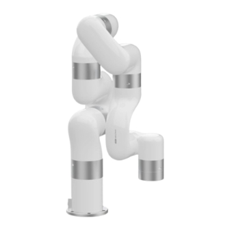
User Manual-Hardware Section 1. Hardware Installation Manual 1.1. The Hardware Composition of xArm 1.1.1. Hardware Composition The composition of robotic arm hardware includes: • Robotic Arm(Figure 2-1) • Control Box (Figure 2-2) • Robotic Arm Signal Cable (Figure 2-3) •... - Page 23 The xArm robotic arm system consists of a base and rotary joints, and each joint represents a degree of freedom. From the bottom to the top, in order, Joint 1, Joint 2, Joint 3, etc. The last joint is known as the tool side and can be used to connect end-effector (e.
- Page 24 Emergency Stop: press the emergency stop button to power off the xArm, and the power indicator will go out. Power-on: when the button is rotated in the direction indicated by the arrow, the button is pulled up, the xArm power indicator lights up, and the arm is powered. Note:...
- Page 25 1.1.3. Three-Position Enabling Switches The three-position enabling switches is composed of three switches and an emergency stop button. The specific functions are shown in the following table: First-position Second-position Third-position Emergency stop switch switch switch Stops the motion of the robotic arm Pause Pause Stop...
-
Page 26: Robot Installation
EMERGENCY STOP Press the button to power off the xArm; Rotate the button, the ROBOT power indicator of the xArm lights up. 1.2. Robot Installation 1.2.1. Safety Guidelines for the Robot Environment 1. Make sure the arm is properly and safely installed in place. - Page 27 tight. 3. The robotic arm should be installed on a sturdy surface that is sufficient to withstand at least 10 times the full torsion of the base joint and at least 5 times the weight of the arm. 1. The robotic arm and its hardware composition must not be in direct contact with the liquid, and should not be placed in a humid environment for a long time.
- Page 28 e. Install end-effector 1.2.2.1. Define a Robotic Arm Workspace The robotic arm workspace refers to the area within the extension of the links. The figure below shows the dimensions and working range of the robotic arm. When installing the robotic arm, make sure the range of motion of the robotic arm is taken into account, so as not to bump into the surrounding people and equipment (the end-effector not included in the working range).
- Page 29 Working space of xArm7 (unit: mm) Note : The following working range diagrams are only for safety assessment.
- Page 30 Working space of xArm5 and xArm6 (unit: mm) Note : The following working range diagrams are only for safety assessment.
- Page 31 1.2.2.2. Robot Installation The robotic arm has five M5 bolts provided and can be mounted through five ∅5.5 holes in the base of the robotic arm. It is recommended to tighten these bolts with a torque of 20N·m. Robot Base Mounting (unit: mm)
- Page 32 1.2.2.3. Robotic Arm is Connected to the Control Box Plug the connector of the Robotic Arm Power Supply Cable and the Robotic Arm Signal Cable into the interface of the Robotic Arm. The connector is a foolproof design. Please do not unplug and plug it violently;...
- Page 33 1.2.2.5. End-effector Installation The End-effector flange has 6 M6 threaded holes and one Ф6 positioning hole, where the end-effector of two different sizes can be mounted. If the effector does not have a positioning hole, the orientation of the end-effector must be documented in a file format, to avoid errors and unexpected results when re-installing the end-effector.
- Page 34 Mechanical dimensions of end-effector flange (unit: mm) Drawing of too I/O 1. Make sure the tool is properly and safely bolted in place. 2. If the end-effector does not have a locating hole,...
-
Page 35: Power Supply For The Robotic Arm
Control Box and the robotic arm. • Ensure the network cable or RS-485 cable is properly connected. • Ensure the power cable for the Control Box is properly connected. • Ensure the xArm will not hit any personnel or equipment within the working range. - Page 36 3. Rotate the emergency stop button in the direction indicated by the arrow and is pulled up, at which point the xArm power indicator (ROBOT PWR) lights up. 4. Use the xArm Studio / SDK command to complete the operation of enabling the robotic arm. (enable the servo motor) 1.3.3.
- Page 37 (2) Ensure the power indicator light is off. 2. Shutdown the control box (1) Turn off the power supply of the control box. (The power switch takes about 5 seconds to turn off the power of the control box. Please do not restart the control box within 5 seconds after turning off the power supply) Unplugging the power cord directly from the wall outlet to shut down the system may result in damage to the file...
-
Page 38: Electrical Interface
2. Electrical Interface 2.1. AC Control Box 2.1.1. Connect the Control Box to the Robotic Arm 1. The robotic arm power supply cable connects the power port of the robotic arm and the ROBOT power port of the control box. 2. - Page 39 2.1.2. Power Connection There is a standard IEC plug at the end of the control box’s main cable. Connect a local dedicated main outlet or cable to the IEC plug. The control box is powered by 100V-240V AC (the input frequency is 47- 63HZ) and its internal switching power supply converts 100V-240V AC into 12V, 24V DC, which supplies power to the load of the control box and the robotic arm.
-
Page 40: Dc Control Box
2.1.3. Definition of the Robotic Arm Industrial Connector 6-Pin Industrial Connector (Robot Communication ) Industrial connector wire sequence Functional definition 485-A Arm 485-B Arm 485-A Tool 485-B Tool 2.2. DC Control Box 2.2.1. External Interfaces of Control Box Except that the DC Control Box is connected to different power sources, the other electrical interface specifications and functions are the same as the AC Control Box. - Page 41 DC PWR: VP+:Connect to 24V-72V DC Input PE: Connect to the control housing (Leakage Protection), not a must GND: Connect to the ground ROBOT communication cable:...
-
Page 42: Electrical Alarms And Cautions
2.2.2. Cable Connection 2.2.3. Specification of External Power DC1300 Input 24V-72V DC Output 24VDC 672Wmax I/O power supply 24V 1.8A(Internal power supply) 24V 3A(External power supply) 2.3. Electrical Alarms and Cautions Always follow the warnings and cautions below when designing and installing a robotic arm application. - Page 43 IEC standard will cause abnormal behaviour of the robotic arm. Extremely high signal levels or excessive exposure can cause permanent damage to the robotic arm. UFACTORY (Shenzhen) Technology Co., Ltd. is not responsible for any loss caused by EMC problems.
-
Page 44: End-Effector I/O
1. When wiring the electrical interface of the Control Box, the Control Box must be powered off. 2.4. End-Effector I/O At the tool side of the robotic arm, there is an avionic socket 12-pin female industrial connector. This connector provides power and control signals for the grippers and sensors used on a particular robotic arm tool. - Page 45 There are 12 pins inside the cable with different colors, each color represents different functions, please refer to the following table: Pin sequence Color Signal Brown +24V(Power) Blue +24V(Power) White 0V (GND) Green 0V (GND) Pink User 485-A Yellow User 485-B Black Tool Output 0 (TO0)...
- Page 46 collector (OC). When the digital output is activated, the corresponding connector will be driven to GND. When the digital output is disabled, the corresponding connector will be open (open collector/open drain). The electrical specifications are as follows: Parameter Typical Unit Open-circuit Voltage -0.5 Voltage when sinking 50mA...
- Page 47 2.4.2. Digital Input The digital input is already equipped with a pull-down resistor. This means that the reading of the floating input is always low. The electrical specifications are as follows: Parameter Typical Unit Input Voltage -0.5 Logic Low Voltage Logic High Voltage Input Resistance Ω...
- Page 48 Pull-down Resistors in the 4mA to 20mA Current Ω Resolution Range 1. In the current/voltage mode, the analog input does not provide over-voltage protection. Exceeding the limits in the electrical code may result in permanent damage to the input port. 2.
-
Page 49: Control Box Electrical Io
2.4.3.2. Differential Analog Input The following figures show how the analog sensor is connected to the differential output. Connect the negative output to GND (0V), and it can work like a non-differential sensor. Voltage Mode Current Mode 2.5. Control Box Electrical IO This chapter explains how to connect devices to the electrical I/O outside of the control box. - Page 50 General Specifications for all Digital I/O 2.5.1. This section describes the electrical specifications for the following 24V digital I/Os for the Control Box. • Dedicated safety I/O. • Configurable I/O. For the specific configuration functions of IO, see the following table: Configurable Function CI0-CI7 DI0-DIO7...
- Page 51 Offline Task Running Robot Enabled Emergency Stop is Pressed It is very important to install xArm according to the electrical specifications. All the I/O must comply with the specifications. The digital I/O can be powered by a internal 24V power supply or by an external power supply by configuring the power junction box.
- Page 52 The electrical specifications for the internal and external power supplies are as follows. Terminal Parameter Min. Value Typical Value Max. Value Unit Built-in 24V Power Supply [PWR - GND] Voltage [PWR - GND] Current External 24V Input Requirement [24V - 0V] Voltage [24V - 0V] Current...
- Page 53 There is no current protection on the digital output of the Control Box. If the specified values exceeded, permanent damage may result. 2.5.2. Dedicated Safety I/O This section describes the dedicated safety inputs and their configurations of the safety I/O. Please follow the universal specifications in Section 2.4.1.
- Page 54 The functional differences are as follows. Emergency Stop Protective Stop Stops the motion of the robotic Program execution Stop Suspend The power supply of the robotic Reset Manual Auto or manual Usage frequency Not frequent No more than once per run Need re-initiation Only releasing the brake cycle...
- Page 55 2.5.2.3. Share Emergency Stop with other Machines When a robotic arm is used with other machines, it requires to set up a common emergency stop circuit in most of the time. The following figure shows that two robotic arms share an emergency stop button (the connection method shown in the figure below also applies to multiple robotic arms sharing an emergency stop button).
- Page 56 This configuration is only for applications where the operator is unable to close the door from behind. Configurable I/O can be used to set the reset button outside the door, as to reactivate the movement of the robotic arm. Another example of an automatic recovery is the use of a safety pad or a safety laser scanner, see the figure below.
- Page 57 1. Configure "CI0" as the safeguard reset in xArm Studio. The specific steps are as follows: Enter "Settings" - "I/O" - "Input" - Configure CI0 as safeguard reset -"Save". 2. If xArm needs to resume motion, connect SI0 and SI1 to GND, and...
- Page 58 CI0 to GND; if xArm needs to pause the motion, disconnect SI0 and SI1 from GND. Note: DI0-DI7 are not equipped with the following three functions: stop moving, safeguard reset, and reduced mode.
- Page 59 Note: It is highly recommended to use a protection diode for inductive loads as shown below. 2.5.3.2. Configurable Input The digital input is implemented in the form of a weak pull-up resistor. This means that the reading of the floating input is always high. Users must follow the electrical specifications set in the 2.4.1 ‘universal specification’.
- Page 60 2.5.3.3. Communicate with other Machines or PLCs If general GND (0V) is established and the machine uses open-drain output technology, digital I/O and other can be used device communication, see the figure below. 2.5.4. General Analog I/O This type of interface can be used to set or measure voltage (0-10V) going into or out of other devices.
- Page 61 I/O is not isolated from the control box. • Use shielded cables or twisted pairs. Connect the shield to the “GND” terminal on the “Power” section. Terminal Parameter Min. Value Typical Value Max. Value Unit Analog Input under Voltage Mode [AIx - AG] Voltage [AIx - AG]...
-
Page 62: Communication Interface
sensor.(Connect to AI0 or AI1) Communication Interface 2.6. The Control Box provides Ethernet interface, as shown in the figure below. 2.7. Ethernet TCP/IP The control box provides a gigabit Ethernet interface. - Page 63 Ethernet connection steps: • The control box and the computer are connected via Ethernet. One end of the network cable is connected to the network interface of the control box, and the other end is connected to the computer or LAN network interface.
- Page 64 192.168.1.*, check if the network proxy is enabled, and check if the robotic arm’s IP address conflicts with that of other devices in the LAN. Please change the computer IP address to the same network segment and close the computer's network proxy. To test whether the computer can communicate with the robotic arm, open the command terminal and input ‘ping 192.168.1.* (the IP address of the robotic arm)’.
-
Page 65: End-Effector
3. End-Effector 3.1. Gripper The gripper is the end-effector of the robotic arm, which can grasp objects dynamically. The value range of the gripper opening and closing is: -10 to 850. The larger the value, the greater the stroke of the gripper, meaning the smaller the value, the smaller the stroke of the gripper. - Page 66 3.1.1. Gripper Installation Installation of gripper: 1. Move the robotic arm to a safe position. Avoid collision with the robotic arm mounting surface or other equipment; 2. Power off the robotic arm by pressing the emergency stop button on the control box; 3.
- Page 67 to ensure that power indicator of the robotic arm is off, as to avoid robotic arm failure caused by hot-plugging; 2. Due to limited length of the gripper connection cable, the gripper connector and the tool/end effector connector must be on the same side;...
- Page 68 The gripper of the robotic arm in the zero position will exceed the mounting surface. Note: For detailed instructions on the xArm gripper, please refer to the xArm gripper user manual, download link:...
-
Page 69: Vacuum Gripper
3.2. Vacuum Gripper The vacuum gripper can dynamically suck the smooth plane object with payload ≤5kg. The vacuum gripper is equipped with 5 suction cups, which can be partially selected for use according to the size of the object surface, and the unused suction cup needs to be sealed. - Page 70 3.2.1. Vacuum Gripper Installation Installation of vacuum gripper: 1. Move the robotic arm to a safe position. Avoid collision with the robotic arm mounting surface or other equipment; 2. Power off the robotic arm by pressing the emergency stop button on the control box;...
- Page 71 1. Python-SDK and xArm Studio provide wrapped functions that can be called to turn on/off the vacuum gripper. xArm Studio-Blockly Command-End Effector-Vacuum Gripper. 2. For detailed instructions on the xArm vacuum gripper, please refer to the xArm vacuum gripper user manual, download link: https://www.ufactory.cc/pages/download-xarm...
-
Page 72: Xarm User Manual-Software Section
With this application, you can set parameters, move the robotic arm in live control, and create a motion trajectory by simply drag and drop the code blocks of Blockly. xArm Studio allows users to plan the motion trajectory for the robotic arm without programming skills. -
Page 73: Hardware Preparation
1.1 Hardware Preparation Before using xArm Studio, you must ensure that the hardware is installed correctly and all the protective measures for the workplace environment have been implemented. 1. The robotic arm is fixed on the plane; protective measures are in place within the range of motion. -
Page 74: Connect To The Robotic Arm
4. Check if the control box is turned on, if the status indicator of the control box is on, it means the control box is turned on. 5. Check if the network is connected. If the network indicator in the middle of the control box flashes frequently, it means the network communication is normal. - Page 75 (2) The control box, PC and router are connected by Ethernet cable. (3) PC and router are connected by wireless network, and control box an d router are connected by Ethernet cable. Note: It is not recommended because of the delay and packet loss of wireless connection.
- Page 76 (4) The control box, PC and network switch are connected by Ethernet cable. 1.2.2 IP Configuration Before connecting the robotic arm with xArm Studio (communication with the robotic arm), make sure that the IP address of the computer and...
- Page 77 the IP address of the control box are on the same network segment. When the control box is shipped from the factory, the default IP address is 192.168.1.xxx (The factory IP address of the device has been marked on the side of the control box). Therefore, to successfully communicate with the control box, the IPV4 network segment on the computer must be between 192.168.1.1-192.168.1.255 (cannot be the same as the IP address tail number of the control box).
- Page 78 Step3: Open the “Properties” Step4: Open the “IPV4”...
- Page 79 1.2.3 Connect to the Robotic Arm There are the following two ways to communicate with the robotic arm. 1. If you access xArm Studio software, you can communicate with the robotic arm through the following steps: (1) Download xArm Studio...
- Page 80 (the default IP address of the device has been marked on the side of the control box) 2. If you use a browser to access xArm Studio, you can communicate with the robot through the following steps:...
- Page 81 1.2.4 Return to the Search Interface PC: Click 【Tool】 - 【Search】 to return to the search interface.
-
Page 82: Xarm Studio Homepage
1.3 xArm Studio Homepage 1.3.1 xArm Studio Homepage Parameters The homepage displays the number of axes currently connected to the robotic arm, Controller IP, Robot State, TCP Payload, Collision Sensitivity, Robot-Mounting, and Motion Enable. Robot State: 【Error】 indicating that the robotic arm has not been enabled, or the robot is in error state. - Page 83 Robot】becomes 【Robot Enabled】. 1.3.2 5 Main Functional Modules of xArm Studio xArm Studio mainly consists of 5 main functional modules: Live Control: Gives the ability to control the position of the xArm and adjust its posture. Blockly: A graphical programming tool that allows users...
-
Page 84: Robotic Arm Setting
Language: Switch language in the upper right corner of the toolbar - 【Language】 may switch between Simplified Chinese / English. Tool: 【Tools】 - 【Search】 to return to the interface of ‘search the robotic arm’. 【Tools】 - 【Check for Updates】 to check the software updates. Help: 【Help】Use the drop-down window to download the manuals of the robotic arm, contact technical support, open forums, and visit GitHub. - Page 85 1.4.1 Motion Settings 1.4.1.1 Linear Motion Acceleration: The acceleration of linear motion. The larger the value, the less time it takes to reach the set speed. It is recommended to be set within 20 times the maximum speed value for a smooth trajectory.
- Page 86 1.4.1.2 Joint Motion Acceleration: The acceleration of joint motion. The larger the value, the less time it takes to reach the set speed. The range is recommended to be within 20 times the maximum operating speed [20*180°/s]. Joint step: Set the step length for fine adjustment of single joint rotation in Live-control.
- Page 87 Steps for setting the initial position: 1. Click【Settings】button on the homepage. Enter 【Motion, then click the 【Set】 button next to the Initial Position. 3. Set the initial position of the xArm in Live-control. 【Confirm】: Save the changes. 【Cancel】: Cancel the changes.
- Page 88 1.4.2 End Effector ⚫ When the end effector provided in the option is installed at the end of the xArm, select the corresponding end effector.
- Page 89 The end effectors currently supported by xArm are: xArm Gripper, xArm vacuum Gripper, xArm BIO Gripper, Robotiq-2F-85 Gripper, Robotiq-2F- 140 Gripper. Take the xArm Gripper as an example. xArm Gripper Note: 1. The opening and closing speed of the gripper can be adjusted.
- Page 90 Version]. 4. When "TCP payload compensation" is turned on, the default TCP payload will be changed to the TCP payload parameter of the gripper. ⚫ When installing other end effectors (not officially provided) at the end of the robotic arm, please choose 【other】. 1.
- Page 91 ⚫ When no end effector is installed at the end of the robotic arm, select [No End Effector] 1.4.3 TCP Settings Set TCP Payload and TCP Offset according to the actual situation. 【TCP Payload】 The load weight refers to the actual mass (end-effector + object) in ●...
- Page 92 【TCP Offset】 Setting the Tool Coordinate Offset with respect to the initial tool ● frame located at the center of the flange (Frame B in the above figure). The position coordinates X, Y, and Z determine the position of TCP, while Roll, Pitch, and Yaw determine the orientation. When the specified value is zero, TCP coincides with the centre point of the tool output flange.
- Page 93 【Set as default】 Set the payload data to the payload of the current robotic arm and ● display the current payload at the top, which is used for controlling the entire robotic arm and is related to the normal use of manual mode and collision detection.
- Page 94 shown in the above figure). The current robotic arm must be mounted on a steady floor if automatic identification is selected. The robotic arm needs to run a series of action commands to calculate the parameters of TCP payload. In addition, it is important to ensure the safety of equipment and personnel near the robotic arm.
- Page 95 data can be referenced during Blockly programming. 【Set as default】: Set the offset data to the offset of the current robotic arm and display the current offset at the top. 【New】: Create a new offset record. When creating a new TCP offset, there are two ways to set the new TCP offset parameters, as shown in the figure below: 1) Manual Input When the TCP offset parameter of the end effector is known, you can...
- Page 96 【Delete】: Delete the selected offset data. Note: the current default offset data cannot be deleted. 【Save】: Save for the newly added offset record, setting the default offset, and deleting the offset record. 【Cancel】: Cancel saving the newly added offset record, setting the default offset, and deleting the offset record.
- Page 97 1.4.4.1 Input The following functions (if configured), can be triggered by low-level input signals. 【General Input】The user can use the IO freely in Blockly or SDK program only when the controller input is set as a general input, otherwise it will cause a function conflict. For example, if CI 0 is configured as an offline task, CI 0 should not be used in any program.
- Page 98 SI, refer to 2.4.2.5.Protective Stop with Reset Button 【Offline Task】 Offline Task can add multiple Blockly to be triggered through I/O. As shown in the figure above, CI0 is set as Offline Task and a Blockly project is added. Click 【Add】...
- Page 99 1.4.4.2 Output The below functions can be configured for each output. 【General Output】The user can use the IO freely in Blockly or SDK program only when the controller output is set as general output, otherwise it will cause function conflict. For example, if CO 0 is configured as motion stopped, CO 0 should not be used in any program.
- Page 100 • Enter emergency stop via CI. • Stop button of xArm Studio and Emergency stop code block of Blockly. • Emergency stop API of SDK. 【Robot Moving】When the robotic arm is moving, the output is high.
- Page 101 1.4.4.3 IO Commissioning In this interface, the IO input status and IO output status of the control box can be monitored, and the IO output status of the control box can be controlled by clicking the button.
- Page 102 1.4.5 Safety Settings 1.4.5.1 Safety Boundary Safety Boundary When this mode is turned on, the working range of the robotic arm in ● Cartesian space can be limited. If the tool center point (TCP) of the robotic arm exceeds the set safety boundary, the robotic arm will stop moving.
- Page 103 1.4.5.2 Reduced Mode Reduced Mode When this mode is turned on, the maximum linear speed, maximum ● joint speed, and joint range of the robotic arm in Cartesian space will be limited.
- Page 104 SN of XF1300/XI1300/XS1300 and later versions, the built-in IMU of the robot arm will detect the direction of gravity. When the deviation between the installation direction you set and the installation...
- Page 105 direction detected by the IMU exceeds 10°, the software will pop-up prompts. 【Floor (0 °, 0 °)】 The default method is horizontal installation, and the horizontally ● mounted robotic arm does not need a tilt angle and a rotation angle. 【Ceiling (180 °, 0 °)】...
- Page 106 The initial position of the robotic arm: On the horizontal plane, when the user is facing the robotic arm side, ● the initial position is on the left-hand side of the user in a downward direction. Tilt angle: The initial position of the robotic arm and the base of the robotic arm to be mounted should be in a tilt angle, which ranges from 0 to 180°.
- Page 107 Make sure the robotic arm is properly placed according to the actual use. Must be mounted on a sturdy, shock-resistant surface to avoid the risk of rollover of the robotic arm. 1.4.7 Timed Tasks Timed tasks can schedule the offline task to run at a specific time or within a time range in the future, without the need for an I/O triggering signal.
- Page 108 【Timing Task】: The robotic arm will run the added tasks during the timing range within the set effective time according to the system time of the control box. 【Periodic Task】: The robotic arm will periodically run the added tasks during the timing range within the set effective time according to the system time of the control box.
- Page 109 within the set time. 【Expired】: The set time for the project has expired 【 】: Delete the tasks added under the project. 1.4.8 Coordinate System In this interface, the user can set the coordinate offset to customize the user coordinate system. X, Y, Z are coordinate values that are offset...
- Page 110 relative to the base coordinate system. Roll, Pitch, Yaw represents the angular values of orientation relative to the base coordinate system. After this offset setting, user coordinate system becomes the world origin instead of robot base. 【New】: Create a new user coordinate offset. When creating a new base coordinate offset, there are two ways to set the new base coordinate offset parameters, as shown in the figure below:...
- Page 111 teaching 4 points. 【Select】: Select the data to be deleted. 【Set as Default】: Set the offset data as the default offset. 【Default】: The data is the default current base coordinate offset. 【Cancel】: Cancel the selection. 【Save】: Save the modified data. 【Discard】: Discard the modified data.
- Page 112 1.4.9 Advanced Settings 1.4.9.1. Advanced Parameters If you want to modify the joint jerk and TCP jerk of the robotic arm, you can modify time here. Note: 1. The jerk affects the acceleration performance of the robotic arm. In general, we do not recommend modifying this parameter. 2.
- Page 113 4. When the robotic arm is moving, the jerk can not be modified. 1.4.9.2. Assistive Features 【Orientation Control】 xArm supports adjusting the rotation of the robot arm through the axis- angle and R/P/Y. Generally, it is recommended to use the axis-angle since the axis-angle control is more intuitive. The choice here determines the TCP control mode of the xArm Studio Live Control page.
- Page 114 【Quick Copy】 After turning on this button, the TCP coordinates and joint angle ● values of the xArm can be copied on the real-time control interface. 【Run Package Blockly Project】 Run Package Blockly Project can avoid the Blockly program from ●...
- Page 115 【Quick access switch】 After enabling quick access, you can quickly adjust parameters ● through the【Quick access button】in any interface of xArm Studio. 【Quick access】 You can select the parameters you want to access quickly, and the ● selected parameters will be displayed on the quick setting interface.
- Page 116 1.4.9.3. Advanced Tools...
- Page 117 PID Parameters Settings Steps for changing PID parameter: 1. Select PID-PARAMETERS-1 (or PID-PARAMETERS-2). 2. Then click [Save]. In the following cases, the PID parameters cannot be modified: 1. If the robotic arm is not enabled, the PID parameters cannot be modified.
- Page 118 1. If the robotic arm shakes heavily executing motions with payload. Note: 1. Changing The PID parameter can only be performed if UFACTORY technical support recommends changing the PID parameters. (contact technical support: support@ufactory.cc) 2. After changing the PID parameters, it may cause the robotic arm to shake or increase safety risk.
- Page 119 Friction Identification...
- Page 120 When the robotic arm needs friction identification, please input the SN of the robotic arm base for friction identification. The following situation can be improved by modifying the friction identification: 1. If manual mode or collision detection performance is far from satisfying.
- Page 121 Clear the IO output when the robot is stopped After turning on 【Clear IO output when the robot is stopped 】if the robotic arm receives a stop command, 【Controller Digital Output】or 【Tool Digital Output 】will be set to the invalid state. Otherwise, the 【Controller Digital Output】...
- Page 122 When the mode is turned on, it will prevent the xArm from causing self- ● collision. Joint Tools Joint Status In this interface, you can get the joint current value and joint voltage value of the robotic arm. The range of the joint voltage value of the robotic arm is: [0, 50V] The range of the joint current value of the robotic arm is: [0, 35A] Note: When using the above functions, the joint firmware version≥...
- Page 123 2. Unlock Joints Click【lock】 to unlock a single joint. The unlocked joint does not have any force to provide and thence external force support is needed. At this time, the joint can be dragged by hand to rotate. After confirming the position, please re-lock all the joints manually.
- Page 124 peripheral facilities. 2. The operation of the unlocking joint is mainly used to adjust the posture of the robotic arm to a relatively safe position when the error is reported by the robotic arm. Attention should be paid to adjusting the joint into the range manually when it exceeds the range of the joint.
- Page 125 PID parameters. And you can clear the multi-turn error of the robotic arm and modify the speed threshold of the robotic arm. Note: This function should be completed under the guidance of technical support. (Please contact the technical support by the email: support@ufactory.cc)
- Page 126 Configuration File 1. Click the 【Export Configuration】button to export the parameters of the robotic arm as a configuration file. The robotic arm parameters that can be exported mainly include: motion parameters, TCP offset, TCP payload, IO settings, safety boundary, installation methods, coordinate systems, and advanced parameters. 2.
- Page 127 file containing the parameters of the robotic arm. 3. Click the 【Factory Reset】button, and the robotic arm will restore the factory settings mode. Note: (1) When multiple robotic arms need to share a set of configuration parameters, click the 【 Export Configuration 】 button to export the configuration file of a robotic arm that has been set.
- Page 128 Note: Please keep the new password properly. If the password is lost, you will need to contact UFACTORY to reset the password. 1.4.10 System Settings System Settings mainly include Check Update, System Information, Network Settings, and Log. Check Update Software updates for xArm Studio, and firmware updates for the ●...
- Page 129 System Information Display the IP address of the connected robotic arm, the firmware ● version of the arm, and the xArm Studio software version. Network Settings Display the IP address of the robotic arm, subnet mask, broadcast ●...
- Page 130 1.4.10.1 System Information On the page of System Information, the control box can be rebooted or the joint can be operated, the degree of freedom (number of axis) of the current robotic arm, IP address, firmware version, SN address, and software version of the robotic arm can be checked.
- Page 131 Access to Control Box Shutdown Access to [Settings]-[System Settings]-[System Information] ● Shutdown / Reboot The control box can be shut down or restarted. Note that the shutdown / reboot button does not turn off the power supply and the main power supply to the robotic arm.
- Page 132 3 to 4 minutes. Note: The 【xArm shutdown】 and【 xArm Reboot】buttons do not affect the main power supply of the control box and the power supply of the robotic arm.
- Page 133 : Click this button to check whether the control box is connected to the Internet. Note: Note: For detailed steps on updating xArm Studio and xArm firmware, please refer to Appendix 4-xArm Software/Firmware Update Method. 1.4.10.3 Network Settings The IP address, subnet mask, broadcast address, and default gateway...
- Page 134 change the IP address of the control box and add DNS. Note: If you change the IP address, be sure to mark it on the control box. If you forget or lose the modified IP address, you can use the following method to reset the IP.
- Page 135 5. Enter 192.168.1.111 in the xArm Studio search box, connect the robotic arm. 6. If you need to modify the IP, just modify the IP in [Settings] → [System Settings] → [Network Settings]. (For example: the modified IP is 192.168.1.135)
- Page 136 7. Restart the control box, enter your modified IP in the xArm Studio search box, and connect the robotic arm.
- Page 137 Note: 1. If you need to reset the IP, the xArm firmware version must be ≥ V1.5.0. 2. If you do not unplug the cable connecting RI0 and GND, the next time you restart the control box, no matter what IP address you modify, the IP address of the control box will be automatically changed to 192.168.1.111, so after modifying the IP, Be sure to unplug the cable...
-
Page 138: Live Control
1.5 Live Control 1.5.1 Status Bar The "unconnected robotic arm" indicates that the robotic arm is not connected. Please reconnect the robotic arm on the homepage. If it is not connected, please check if the robotic arm is normally turned on and check if the network connection is normal. - Page 139 Click on the emergency stop button to immediately stop the current motion and clear all cached commands. Note: The “STOP” button in xArm Studio is different from the one on the control box. 1. The “STOP” button in xArm Studio allows the robotic arm to...
- Page 140 【Real Robot】 It can control the motion of the real robotic arm in the interface of ● xArm Studio, and the virtual robotic arm will reflect the position and posture of the real robotic arm in real-time. 【Simulation Robot】 It can control the motion of the virtual robotic arm in the interface of ●...
- Page 141 【Teach sensitivity】. Note: Before opening the manual mode, you must ensure that the installation method of the robotic arm and the payload setting of the robotic arm are consistent with the actual situation, otherwise it will be dangerous. The serial number of robotic arm and the control box need to be matched before Manual Mode can be turned on.
- Page 142 【Settings】 -【Motion Settings】 -【Joint Motion】 -【Joint Step 】. Press-and-hold【+】or【-】for continuous joint motion in a positive or negative direction, which will stop when the mouse is released. To confirm the direction of joint rotation, please refer the figure below: xArm 5 xArm 6 xArm 7...
- Page 143 1.5.6 Linear Motion 1.5.6.1 Introduction Users can control the motion of the robotic arm based on the base coordinate system and TCP coordinate system. The trajectory of tool center point in the Cartesian space is a straight line. Each joint performs a more complex movement to keep the tool in a straight path.
- Page 144 1.5.6.2 TCP Coordinate System A: Base coordinate system B: Tool coordinate system The default TCP coordinate system is defined at the centre point of the end flange of the robotic arm, and it is the result of rotating [180°, 0°, 0°] around the X/Y/Z-axis of the base coordinate system in order.
- Page 145 deflection is needed from position point A to point B, the robotic arm moves in the direction of α angle. If the robotic arm needs to be moved in the direction of the β angle, a new position between the angles of β...
- Page 146 A: base coordinates B: TCP coordinates(if no offset) 1. You must check the TCP offset before recording the Cartesian position. 1.5.7 Operation Mode 1.5.7.1 xArm 6 (xArm 7) Operation Interface...
- Page 147 【 】 It can switch the control functions between the base coordinate ● system and the tool coordinate system. 【Position/Attitude Real-time Display】 X / Y / Z represents the coordinates of the tool center point (TCP) ● position of the robotic arm under the base coordinate offset. Roll/Pitch/Yaw under the Attitude indicates the angle value rotated under the base coordinate offset, which is a description of the azimuth obtained by rotating three times around the selected coordinate...
- Page 148 Motion】 -【Attitude Step】 on the homepage. Note: When the real-time control base coordinate system/tool coordinate system is switched, if the coordinate system offset is not [0,0,0,0,0,0], the "user coordinate system" will be displayed, as shown in the figure below. 1.5.7.2 xArm 5 Operation Interface...
- Page 149 【Aligning】 After clicking this button, the tool flange will be adjusted to a ● horizontal attitude, that is, pitch and roll will be adjusted to the fixed values of 0 ° and 180 °. 1.5.8 Zero Position, Initial Position 【ZERO POSITION】 Indicates all joint angles values are zero.
- Page 150 1.5.9 Speed Setting It is used to adjust the motion speed of the live control interface of xArm. (Note that the maximum speed of the live control interface is not the actual maximum motion speed of the robotic arm. If you want the program to run at high speed, you can add a speed command in the Blockly motion program).
-
Page 151: Blockly Graphical Programming
continuous, and the robotic arm will have a brief pause between joint command. TCP Operating Speed The Cartesian speed range is from 1mm/s to 1000mm/s. The actual ● maximum speed is also affected by the payload, speed, and posture of the robotic arm. If the set speed is close to the limit speed, the robotic arm will slow down or cause an error mechanism. - Page 152 】Click to create a new folder. 【 】Can be converted to Python code and can be used in the xArm-Python-SDK library. 【My Project— “xxx”】 Click to expand to display all created items, the currently open item "xxx" is displayed when it folds.
- Page 153 【Download All】Click to download all projects. 【 】Click this button, and the 3D simulation model of the robotic arm in the real-time control interface will pop up (as shown in the figure below). When running the program, you can observe the motion posture of the robotic arm in real time.
- Page 154 1.6.2 Blockly Workspace Drag the code block into the action panel, the code execution is top- down, users can drag and drop the code block with the blocks attached from behind together. 【 】Return to the default size and code block at centered position 【...
- Page 155 1.6.2.1 The Right Click Mouse Event in the Workspace Right-click on the blank workspace of the non-code block, the function is mainly for all code blocks: 【Undo】: Undo the previous operation. 【Redo】: Restore the last undo operation. 【Collapse Blocks】: Collapse all code blocks. 【Expand Blocks】: Display all collapsed commands.
- Page 156 1.6.2.2 The Right Click Mouse Event of the Code Block Right-click in the code block, the function of each module pop up: 【Duplicate】: Copy all code blocks of the current workspace, copy/cut shortcuts with the keyboard and paste them into other files. 【Add Comment】: Users can add a description to the code block, which is identified by the symbol .
- Page 157 【Disable Block】: Stop the execution of the running command of the current code block. The opposite is 【Enable Block】. 【Delete 82 Blocks】: Delete the current code block selected by the mouse click. 【Help】: Jump to the Help Page of the corresponding code block. 1.6.2.3 Move/Wait/Edit For some common functions of the motion commands, click【move】...
- Page 158 End-Effector: Contains common commands to control the end-effector, such as gripper, vacuum gripper. Logic: Contains commonly used logic commands. Loop: Contains common loop commands such as multiple loops, infinite loops, and breaking loops. Math: Contains commands for mathematical operations. Advanced: Includes location notes and message reminders. 1.6.4 Setting 【Set TCP speed()mm/s】...
- Page 159 【Set TCP acceleration()mm/s²】 Set the acceleration of the linear motion in mm/s ● 【Set joint speed()°/s】 Set the speed of joint movement in °/s. ● 【Set joint acceleration()°/s²】 Set the acceleration of joint motion in °/s . The default speed and ●...
- Page 160 incremented by 1. It can be used to calculate the number of times the program actually cycles. 1.6.5 Motion 【sleep()s】 After receiving this command, the robotic arm will stop moving for the ● set time, and then continue to execute the following commands. It is mainly used in motion programs that need to do the continuous motion.
- Page 161 With this command, operators can set the state of the robotic arm ● (movement, pause, stop). It is used to control the state of the robotic arm. It is mainly used in condition-triggered programs. 【emergency stop】 The robotic arm immediately stops moving and clears the command ●...
- Page 162 From current position, the whole circle is determined by current ● position and position1 and positon2, “center angle” specifies how much of the circle to execute. 【center angle (°) () 】 Indicates the degree of the circle. When it is set to 360, a whole circle ●...
- Page 163 1.6.6 GPIO(Control Box and End tool interface) The IO interface is made up of a control box interface and an end tool interface, which can be used to acquire, set, and monitor IO interface operations. The control box has 8 digital input interfaces, 8 digital output interfaces, 2 analog input interfaces, and 2 analog output interfaces.
- Page 164 Set the I/O interface of the code block, click 【Set】 to run the ● command. 【set I/O when(X, Y, Z, tolerance)】 When the robotic arm reaches the specified position (the area of the ● sphere specified with the trigger position point (X, Y, Z) as the center (the radius of the sphere is the tolerance radius)), IO is triggered.
- Page 165 =, ≠, >, ≥, <, ≤. IO trigger logic of xArm Studio: 1. xArm Studio obtains the IO state every 100ms, and uses the IO state value obtained for the first time as the initial value. 2. Compare the IO state obtained the second time with the IO state obtained last time.
- Page 166 【set xarm gripper Pos () Speed () Wait (true / false)[move][edit]】 Set the position and the opening and closing speed of the gripper. ● 【set bio gripper Speed () Wait (true / false)[move][edit]】 Set the opening and closing speed of the gripper.
- Page 167 1, it indicates that the object is picked successfully; when the vacuum gripper state is 0, it indicates that the object fails to be picked. 【set xarm vacuum gripper (ON/OFF) object detection (true/false) [set]】 Set the vacuum gripper to be on and off. ●...
- Page 168 1.6.9 Logic 【wait ()】 Wait for the next command to be sent, with the unit of seconds. ● 【if (Condition 1) Run (Command 1)】 If Condition 1 is true, then Command 1 will be run. Otherwise, it will be ● skipped.
- Page 169 block, and combine the two code blocks, as shown below: 3. Click the setting button , the selection box is retracted, if /else sentence setting is completed, as shown below: 1.6.10 Loop 【forever】 The command contained in the loop will be executed in infinite loop. ●...
- Page 170 When the condition is not met, it jumps out of the loop. ● 【break】 Terminate the loop. ● 1.6.11 Math You can use the above code block to do some complex operations such as addition, subtraction, multiplication, and division, exponential operations.
- Page 171 1.6.12 Text 【remark】 Remark the code block, which serves as an indicator and can change ● the color. 【message type】 Types available are: (information/success/warning/error), duration ● indicates the time interval the message is displayed, the unit is in second; the message indicates the content of the prompt message. 【string printing[]】...
- Page 172 【variable printing】 Users can print the added variable and set the font and the color. ● 【Date】 The date and time on which the command was run can be output. ● 1.6.13 Variable 【Create variable】 New variables can be added. After adding a variable, there are three ●...
- Page 173 1.6.14 Function 【to (do something)】 Users can define a new function without a return value. ● 【to (do something) return []】 Users can define a new function with a return value. ● 【if [] return []】 Conditional judgment sentence that can only be placed in the built-in ●...
- Page 174 1.6.15 Set & Edit Motion Coordinates Long press 【Move】 button to move the robotic arm to the position of the current command. Click 【edit】to pop up the live control interface to re-edit the motion coordinates of the current command.
- Page 175 Click 【Save】to save the changes and close the pop-up window. Click【Cancel】 to cancel the changes and close the pop-up window. Note: In the command, there are sequential points such as A / B / C / D. Etc. If the user clicks 【move】 to skip point B from point A to point C, a safety assessment must be carried out to avoid damage to peripheral facilities Due to the complexity of Cartesian commands, Cartesian spatial...
-
Page 176: Python Ide
At this time, the route needs to be re- planned. For details, please refer to "xArm Kinematics-Linear Motion". 1.7 Python IDE Python IDE is a Python development integration environment that can directly use xArm-Python-SDK API and check the Blockly projects converted into Python code. - Page 177 【 】Create a new project. 【 】Create a new file. 【 】Create a new folder. 【 】Rename. 【 】Delete the file. 【 】Run the file. 1.7.1 Create a New Project On this page, all current project files are displayed, including Blockly projects converted into Python code.
-
Page 178: Recording
【 】 Display the current open project and the time it was created. 【 】Delete projects. 【Open】Open the projects and display them in the edit box. Note: , The project folder is not available, please create a new project by yourself. Control Box Command Caching Mechanism: The current control box can cache 2048 commands. - Page 179 recording time is 5 minutes. The playback will completely repeat the motion trajectory during recording, and the playback speed of the trajectory can be set (x1, x2, x4). A recorded trajectory can be imported into Blockly projects. 【 】Pop-up live control panel. 【...
- Page 180 the big difference between the actual load and the set load of the robotic arm, resulting in its self-motion. 【 】Display recording time. 【 】Stop recording. 【Times】Set playback times. 【Speed】Set playback speed. 【 】Download the file. 【 】Delete the file. 【Import Project】Import recorded trajectory.
-
Page 181: Xarm Motion Analysis
2. xArm Motion Analysis In this section, we mainly use Python / Blockly examples to explain a few typical motions in the list below. Motion Joint Linear Arc linear Circular xArm5 Motion Motion motion Motion Motion About Python-SDK: For all interfaces with is_radian, the default value of is_radian is the value at the time of instantiation. -
Page 182: Robotic Arm Motion Mode And State Analysis
All units for angles use degrees (°). 2.1 Robotic Arm Motion Mode and State Analysis 2.1.1 The Motion Mode of the Robotic Arm Motions of the robotic arm: joint motion, linear motion, linear circular motion, circular motion, servoj motion and servo_cartesian motion. The following motions are in position mode (Please refer to 【Robot Movement &... - Page 183 (the maximum receiving frequency of the version before 1.4.0 is 100Hz). If the frequency of sending commands exceeds 250Hz, the redundant commands will be lost. The xArm-Python-SDK interface function we provide also reserves the speed, acceleration and time settings, but they will not work at present. The suggested way of...
- Page 184 1.4.0 is 100Hz). If the frequency of sending commands exceeds 250Hz, the redundant commands will be lost. The xArm-Python-SDK interface function we provide also reserves the speed, acceleration and time settings, but they will not work at present. The suggested way of...
- Page 185 Operators who design the robotic arm motion path must be qualified with the following conditions: 1. The operator should have a strong sense of security consciousness, and sufficient knowledge on robotic arm operations. 2. The operator should have in-depth knowledge on the robotic arm and understands the joint motion mode and the linear motion mode.
- Page 186 (such as ROS Moveit!) planning algorithm.
- Page 187 ● Mode 4: Joint velocity control mode. ● Mode 5: Cartesian velocity control mode 2.1.3 Analysis of the Motion Status of the Robotic Arm 3 states that the control box can set: (Python SDK: set_state ()) ● State 0: Start motion. Can be understood as ready for motion or stand-by.
- Page 188 4 states that the control box can get: (Python SDK: get_state ()) ● State 1: In motion. The robotic arm is executing motion commands and is not stationary. ● State 2: Standby. The control box is already in motion ready state, but no motion commands are cached for execution.
-
Page 189: Motion Of The Robotic Arm
2.2. Motion of the Robotic Arm 2.2.1. Joint Motion To achieve point-to-point motion in joint space (unit: degree), the speed is not continuous between each command. Blockly example: 【Set joint speed() °/s】: Set the speed of joint movement in °/s. 【Set joint acceleration() °/s²】: Set the acceleration of joint motion in °/s2. - Page 190 the current point. The motion trajectory of the robotic arm in the above example is as follows: Python example: arm.set_servo_angle(angle=[0.0, 7.0, -71.2, 0.0, 0.0, 0.0], speed=8, mvacc=1145, wait=True) arm.set_servo_angle(angle=[0.0, 7.0, -51.2, 0.0, 0.0, 0.0], speed=8, mvacc=1145, wait=True) arm.set_servo_angle(angle=[0.0, 7.0, -91.2, 0.0, 0.0, 0.0], speed=8, mvacc=1145, wait=True) The interface set_servo_angle is described in Table 2.1: Table 2.1 Description of set_servo_angle set_servo_angle...
- Page 191 b) If servo_id is None or 8, E.g. : arm.set_servo_angle (angle = [30,45,0,0,0,0,0], is_radian = False) joint speed (the default unit is ° / s): speed Unit: if is_radian = True, the unit is rad / s; if is_radian = False, the unit is °...
- Page 192 Blockly: The motion trajectory of the robotic arm in the above example is as follows: Key parameter description Radius = 60 Radius =60 in the "move joint" command refers to setting the radius of the transition arc R = 60mm, which is used to achieve a smooth transition of the arc in a joint motion.
- Page 193 (1) Radius> 0. For example, setting Radius = 60, the turning trajectory is as shown in the arc in the figure below, which can achieve a smooth turning effect. Note: The radius of the arc is smaller than D and D (2) Radius = 0.
- Page 194 The wait in the "move joint" command indicates whether it is necessary to wait for the execution of this command before sending the next command. Note: If you need to plan for speed continuous motion, make sure wait = false, to buffer the commands to be blended. 2.2.2.
- Page 195 controls the TCP orientation in the unit of degree. • Linear motion and circular linear motion belong to the Cartesian space trajectory planning, which needs to be solved by inverse kinematics. Therefore, there may be no solution, multiple solutions, and approximated solutions; and due to the nonlinear relationship between the joint space and Cartesian space, the joint motion may exceed its maximum speed and acceleration limits.
- Page 196 Python example: arm.set_tcp_jerk(2000) arm.set_position(x=205.0, y=100.0, z=110.4, roll=180.0, pitch=0.5, yaw=0.0, speed=100, radius=- 1.0, wait=True) arm.set_position(x=205.0, y=120.0, z=110.4, roll=180.0, pitch=0.5, yaw=0.0, speed=100, radius=- 1.0, wait=True) arm.set_position(x=205.0, y=140.0, z=110.4, roll=180.0, pitch=0.5, yaw=0.0, speed=100, radius=- 1.0, wait=True) arm.reset() The interface set_position() is described in Table 2.2: Table 2.2 set_position description set_position Description...
- Page 197 Note: When the xArm firmware version≥1.6.0, if you need to plan Lineb motion, you need to adjust the TCP speed below 200mm/s for debugging, otherwise there will be a high security risk.
- Page 198 Key parameter description Radius = 5 Radius = 5 in the "move (arc) line" command refers to setting the radius of the transition arc between two straight lines R = 5mm, which is used to achieve a smooth transition of the arc in a straight motion. The parameters of Radius can be set as Radius>...
- Page 199 with no deceleration, as shown in the figure below. Note: If the motion of the robotic arm is a reciprocating linear motion, you need to set radius=0. If the radius>0, the robotic arm may report a motion planning error. (6) Radius <0. There is no arc transition at the turn, this speed will not be continuous between this and next motion, as shown in the figure below, speed will decelerate to 0 at point B before moving to C.
- Page 200 Python example: arm.reset(wait=True) arm.set_pause_time(0.5) while True: arm.set_position(x=400, y=-100, z=250, roll=180, pitch=0, yaw=0, radius=50,speed=200, wait=False) arm.set_position(x=400, y=100, z=250, roll=180, pitch=0, yaw=0, radius=50,speed=200, wait=False) arm.set_position(x=300, y=0, z=250, roll=-180, pitch=0, yaw=0, radius=50,speed=200, wait=False) set_position interface: refer to Table 2.2. The set_pause_time interface is described in Table 2.3: Table 2.3 set_pause_time description set_pause_time Description...
- Page 201 in a common line. Set the center angle: 1. If 0< center angle (°) <360 ° or center angle (°) > 360 °, the motion path of the robotic arm is a circular arc of the corresponding degree; center angle = 60°, the motion trajectory of the robotic arm is: 2.
- Page 202 circle is determined by current position and position1 and positon2, “center angle” specifies how much of the circle to execute. Note: (1) The starting point, pose 1 and pose 2 determine the three reference points of a complete circle. If the motion path of the robotic arm is a circular arc, then pose 1 and pose 2 are not necessarily end points or passing points;...
- Page 203 ⚫ If the positions of point B and C are swapped, point B is (350, - 50,400,180,0,0), point C is (350,50,400,180,0,0), the robotic arm will draw a circle in a counterclockwise direction. The trajectory of the robotic arm is as follows: Python example: arm.set_servo_angle(angle=[0.0, -45.0, 0.0, 0.0, -45.0, 0.0], speed=20, mvacc=500, wait=True) arm.set_position(*[300.0, 0.0, 400.0, 0.0, -90.0, 180.0], speed=300, mvacc=2000, radius=-1.0,...
-
Page 204: Xarm5 Motion Characteristics
pose1 Cartesian coordinates [x(mm), y(mm), z(mm), roll(rad or °), pitch(rad or °), yaw(rad or °)]; pose2 Cartesian coordinates [x(mm), y(mm), z(mm), roll(rad or °), pitch(rad or °), yaw(rad or °)]; percent Percentage of arc moved If is_radian = True, the unit of roll / pitch / yaw is rad; is_radian If is_radian = False, the unit of roll / pitch / yaw is °;... -
Page 205: Singularity
solution. Joint space ● In joint space, the robotic arm has 5 degrees of freedom to control and can switch to joint commands when different orientations are required at the end. Then use the joint command again to return the flange and the base to a horizontal attitude, and you can switch back to Cartesian control. - Page 206 cause 1st Joint speed too high. Figure 2.1 xArm6 singularity 2.Characteristics The characteristic of the singularity is that the planning movement cannot be performed correctly. Coordinate-based planned movements cannot be explicitly translated into joint motions of each axis. When the robot performs motion planning (linear, circular, etc., excluding joint movements) near the singularity point, it will stop to avoid high instantaneous speed of the joint when it passes the singularity point.
- Page 207 Case 1: Singularity encountered during robot teaching a) Switch the robot coordinate system to a joint coordinate system, and pass the singularity point through joint motion. Case 2: Singularities encountered while the program is running a) When encountering a singularity point while running the program, you can modify the position and attitude of the robot and re-plan the path to the target point.
-
Page 208: Typical Examples
3. Typical Examples 3.1. The Use of xArm Vacuum Gripper The download address of the Blockly program: The use of xArm vacuum gripper.blockly The role of this program: execute this program to control the vacuum gripper to suck the target object at the specified position, and then place... -
Page 209: The Use Of Xarm Gripper
(released) the object, it will also jump out of the command and execute the next command. 【set xarm vacuum gripper (ON/OFF) object detection (true/false) [set]】: Set the vacuum gripper to be on and off. -
Page 210: The Use Of The Digital Io
The role of this program: execute this program to control the gripper to grip the target object at the specified position, and then place the target object at the target position. 3.3. The Use of the Digital IO The download address of the Blockly program: The use of the digital IO.blockly The role of this program: If you need to use digital IO to control the motion of the robotic arm, you can trigger the digital IO to perform the... -
Page 211: Cyclic Motion Count
Note: 2. The defined function should be placed in front of the main programs, as shown in the figure above. 3.4. Cyclic Motion Count The download address of the Blockly program: Cyclic Motion Count.blockly Counter counts: Cyclic motion count: By adding 【Counter plus】, each time the command is run, the counter of the Control Box will be incremented by 1. - Page 212 When wait = true, the counting effect of the ++ i class and the counter counting are consistent. 2. wait = false When wait = false, the ++ i class count and the count counter are inconsistent. Because wait = false, the commands will be sent continuously until the control box buffer is full (According to the above example, the number of cycles of the robotic arm is 10 times.
-
Page 213: Appendix
Error processing method: Re-power on, the steps are as follows: ● 1. Turn the emergency stop button on the control box 2. Enable the robotic arm xArm Studio enable method: Click the guide button of the error pop- ● up window. xArm-Python-SDK enable method: Refer to Error Handling Mode. - Page 214 Software Error Code Error Handling Joint Communication Error Please restart the xArm with the Emergency Stop Button on the Control Box. If multiple reboots do not work, please contact technical support. Abnormal Current Detection Please restart the xArm with the Emergency Stop Button on the xArm Control Box.
- Page 215 Single-turn Encoder Error Please restart the xArm with the Emergency Stop Button on the Control Box. Multi-turn Encoder Error Please click "Clear Error", then push the power switch of the Control Box to OFF, wait 5 seconds and then power on again.
-
Page 216: Control Box Error Code And Error Handling
Driver Type Error Please restart the xArm with the Emergency Stop Button on the xArm Control Box. Joint Overvoltage Please reduce the acceleration value in the Motion Settings. Joint Undervoltage Please reduce the acceleration value in the Motion Settings. Please check if the control box emergency stop switch is released. - Page 217 Please go to the "Live Control" page and press the "ZERO POSITION" button to let the robot back to the zero position. Speed Exceeds Limit Please check if the xArm is at singularity point, or reduce the speed and acceleration values. Planning Error Please re-plan the path or reduce the speed.
- Page 218 Command Reply Error Please retry, or restart the xArm with the Emergency Stop Button on the Control Box. If multiple reboots are not working, please contact technical support. Other Errors Please contact technical support. Feedback Speed Exceeds Limit Please contact technical support.
- Page 219 Please check whether the TCP payload setting of the robotic arm and the installation method of the robotic arm match the actual settings. Abnormal Joint Angle Please stop the xArm by pressing the Emergency Stop Button on the Control Box. Control Box Power Board Master and Slave IC Communication Error Please contact technical support.
-
Page 220: Gripper Error Code & Error Handling
1. Re-powering the robotic arm via the emergency stop button on the control box. 2. Enable the robotic arm. a. xArm Studio enable method: Click the guide button of the error pop-up window or the ‘STOP’ red button in the upper right corner. b. xArm-Python-SDK enable method: Refer to Error Handling Method. - Page 221 UFACTORY team for support. Software Error Code Error Handling Gripper Current Detection Error Please restart the xArm with the Emergency Stop Button on the xArm Control Box. Gripper Current Overlimit Please click “OK” to re-enable the Gripper. Gripper Speed Overlimit Please click “OK”...
-
Page 222: Python Sdk Error Code & Error Handling
Please adjust the TCP position command. xArm is not ready. Please check whether the robot is enabled and the state is set correctly. xArm is disconnect or not connect. Please check the network. There are errors that have not been cleared. - Page 223 Please check whether the errors have been cleared, whether the robot arm has been enabled, and whether the robot arm status is set correctly. Other error. Please contact technical support. Parameter error. Tool IO ID error.
-
Page 224: Appendix2-Technical Specifications
Min 8.4 W, Typical 200W, Max 500W Input Power Supply 24 V DC, 16.5 A ISO Class Cleanroom Robotic Arm Mounting Programming xArm Studio/Python/C++/ROS Robotic Arm Communication Protocol Modbus-TCP 2 Digital inputs, 2 Digital outputs, End-effector I/O Interface 2 Analog inputs... - Page 225 Payload (kg) ≤5kg Noise Level (30cm away) < 60dB Communication Mode Digital IO State Indicator Power, Working State Feedback Air Pressure (Low or Normal) Notes: 1. The ambient temperature of xArm is 0-50 °C, please reduce the temperature if continuous...
-
Page 226: Xarm 5 Specifications
1.2 xArm 5 Specifications ±360° -118°~120° Joint Range -225°~11° -97°~180° Payload Degrees of Freedom Weight(robotic arm only) 11.2kg Robot Joints Robot Zero Attitude Joint Rotating Direction... -
Page 227: Xarm 6 Specifications
1.3 xArm 6 Specifications 1,4,6 ±360° -118°~120° Joint Range -225°~11° -97°~180° Payload Degrees of Freedom Repeatability ±0.1mm Weight(robotic arm only) 12.2kg Robot Zero Attitude Robot Joints Joint Rotating Direction 1.4 xArm 7 Specifications 1,3,5,7 ±360°... - Page 228 -118°~120° Joint Range -11°~225° -97°~180° Payload 3.5kg Degrees of Freedom Weight(robotic arm only) 13.7kg Robot Zero Attitude Robot Joints Joint Rotating Direction...
-
Page 229: Appendix3-Faq
2. Guide to use the Vacuum Gripper 3. Guide to download the log file on the xArm Studio 4. Solve the problem that all joints of the xArm are at '0' in the gazebo 5. The Method of the IP Configuration 6. -
Page 230: Appendix4-The Xarm Software/Firmware Update Method
Notes 1) It is recommended to update the xArm firmware and xArm Studio at the same time. 2) After updating, please download the latest "xArm User Manual" and "xArm Developer Manual"... - Page 231 If you use xArm-Python-SDK (xArm-C++ SDK or xArm ROS), after updating the xArm to the latest firmware, you need to obtain the latest xArm-Python-SDK (xArm-C++ SDK or xArm ROS) from GitHub.
- Page 232 2) After decompressing the installation package, run the xarm-tool-gui program that matches your PC's operating system, select the type of robotic arm, and enter the IP address of the xArm control box, then click "Connect". 3) After successful connection, click the [Check Update] button, then click the [Install Online] in the Firmware installation box (xArm Studio installation box), and finally click the [Install] button in the pop-up box;...
- Page 233 4) After the installation is completed, the console of the xarm-tool-gui will display "Install firmware success" (or "Install Studio success"). Finally, click "Reboot Control Box" and wait for the control box to reboot, the reboot usually takes about 2-3 minutes.
- Page 234 2. When you use the following network setting methods, please use xarm-tool-gui tool to update xArm Studio and xArm firmware offline. The control box is directly connected to the PC(The PC is not connected to the Internet)
- Page 235 After decompressing the installation package, run the xarm-tool-gui program that matches your PC's operating system, select the type of robotic arm, and enter the IP address of the xArm control box, then click "Connect". After successful connection, click the [Install Offline] in the Firmware installation box (xArmStudio installation box), then load the corresponding "firmware"...
- Page 236 Click the [Install] button. After the installation is completed, the console of the xarm-tool-gui will display "Install firmware success" (or "Install Studio success"). Finally, click "Reboot Control Box" and wait for the control box to reboot, the reboot usually takes about 2-3 minutes.
- Page 237 (1)The control box, PC and router are connected by ethernet cable The control box, PC and network switch are connected by ethernet cable...
- Page 238 (3)PC and router are connected by wireless network, and control box and router are connected by ethernet Cable. Click [Settings] on the xArm Studio homepage, enter [System Settings] → [Check Update], click "Update". Wait for the system to prompt to restart, and then click "Restart", the...
-
Page 239: Appendix5- Maintenance And Inspection
4. Precautions If there is no IO module on the side of your control box (the IO module is shown in the figure below) and cannot be updated online by xArm Studio, please contact technical support (support@ufactory.cc) to provide a dedicated xarm-tool-gui installation package. -
Page 240: Appendix6- Repair
When cleaning the carbon fiber surface, be careful not to let the liquid penetrate the joints. Appendix6- Repair 1. Repair work must only be done by UFACTORY. After repair work, checks must be done to ensure the required safety level. Checks must adhere to valid national or regional work safety regulations. - Page 241 You need to make an appointment with the local UPS and then send the product to us. (3) UFACTORY will check the product warranty status according to the after-sales policy. (4) Generally, the process takes around 1-2 weeks except for shipment.
-
Page 242: Appendix7-Product Information
section 1.4.9.2 Advanced Tool-Configuration File). Appendix7-Product Information 1.1 Product Mark Robotic Arm Control Box... -
Page 243: Applied Standards
1.2 Applied Standards The xArm 6 robot is certified and tested by SGS, and has passed the EU CE certification. The product meets the relevant requirements of the EU CE directive: • MD 2006/42/EC • EMC 2004/108/EC • EN ISO 10218-1:2011 •... -
Page 244: Use Environment
This standard defines extended EMC immunity requirements for safety- related functions. Conforming to this standard ensures that the safety functions of xArm robots provide safety even if other equipment exceeds the EMC emission limits defined in the IEC 61000 standards. -
Page 245: Transport, Storage And Handling
1.5 Transport, Storage and Handling • Move the robot to the zero position by xArm Studio, then put the xArm robot and Control Box in the original packaging. • Transport the robot in the original packaging. • Lift both tubes of the robot arm at the same time when moving it from the packaging to the installation place. -
Page 246: Special Consumables
1.8 Special Consumables. Fuse specifications:15A 250V 5×20mm Time-Lag glass body cartridge fuse 1.9 Stop Categories A Stop Category 1 and a Stop Category 2 decelerates the robot with drive power on, which enables the robot to stop without deviating from its current path. -
Page 247: Maximum Speed
0.67 1.11 Maximum Speed Mode Typical Scenarios Maximum Speed Teaching mode Live Control Page of xArm Studio 250 mm/s Automatic mode Blockly/ IDE of xArm Studio 1000 mm/s 1.12 Maximum Payload The maximum allowed payload of the robot arm depends on the center... -
Page 248: Specifications
between the center of the tool output flange and the center of gravity. 1.13 Specifications Robotic Arm Model XI1300 1,4,6 ±360° -118°~120° Joint Range -225°~11° -97°~180° Payload Maximum Reach 700mm Degrees of Freedom Repeatability ±0.1mm Maximum Joint Speed 180°/s Weight (robotic arm only) 12.2kg Footprint Ø... - Page 249 Communication Protocol Modbus TCP Weight 3.9kg Operating Temperature 0-50ºC Humidity 25%-85% (non-condensing) Short Circuit Rating Input 1PHASE AC 100-240V 47~63HZ 550Wmax Manufacturer:UFactory Technology Co.,Ltd Address: 2F, Building M-6, Ma Que Ling Industrial Zone, Nanshan District, Shenzhen, Guangdong, China Website: www.ufactory.cc...
Need help?
Do you have a question about the XARM and is the answer not in the manual?
Questions and answers